23
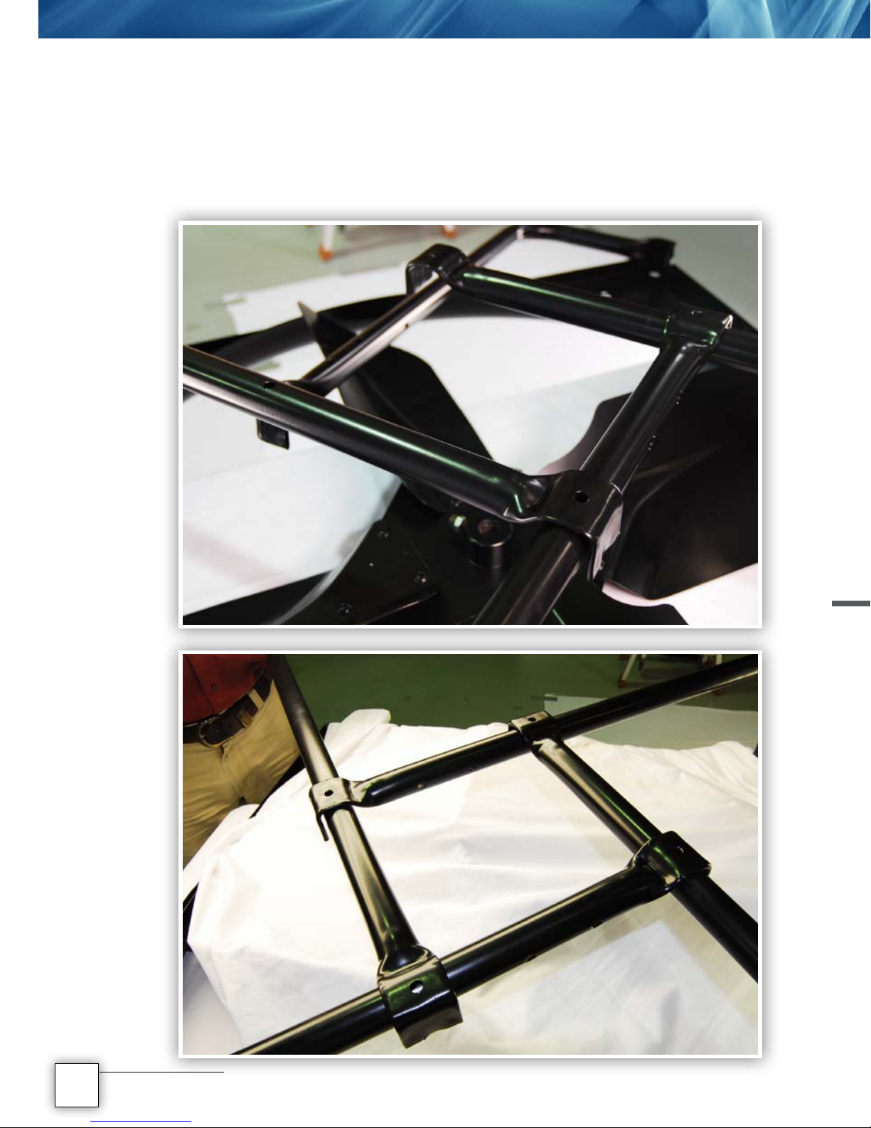
This picture shows the bend bars and fan in position around the fan shroud.
There is no particular start point to lay the bend bars out but what you have
to take care in, is that the bars have a running sequence. Start with the motor
mounting plate bend bar and place it at one of the 4 smaller holes punched
around the fan shroud and lay it over the fan in the middle. Then collect a
bearing housing bend bar (1 of 2 supplied) and lay it underneath the hand of
the motor mounting plate bend bar. What you effectively have, is left and over
right. Then take the bend bar with no additional holes along the shaft and lay
it underneath the 2nd bend bar (left hand over right). The last remaining bend
bar (should have 2 holes along the shaft for the bearing housing) is placed
underneath the 3rd bend bar and over the 1st. Again left hand over right.
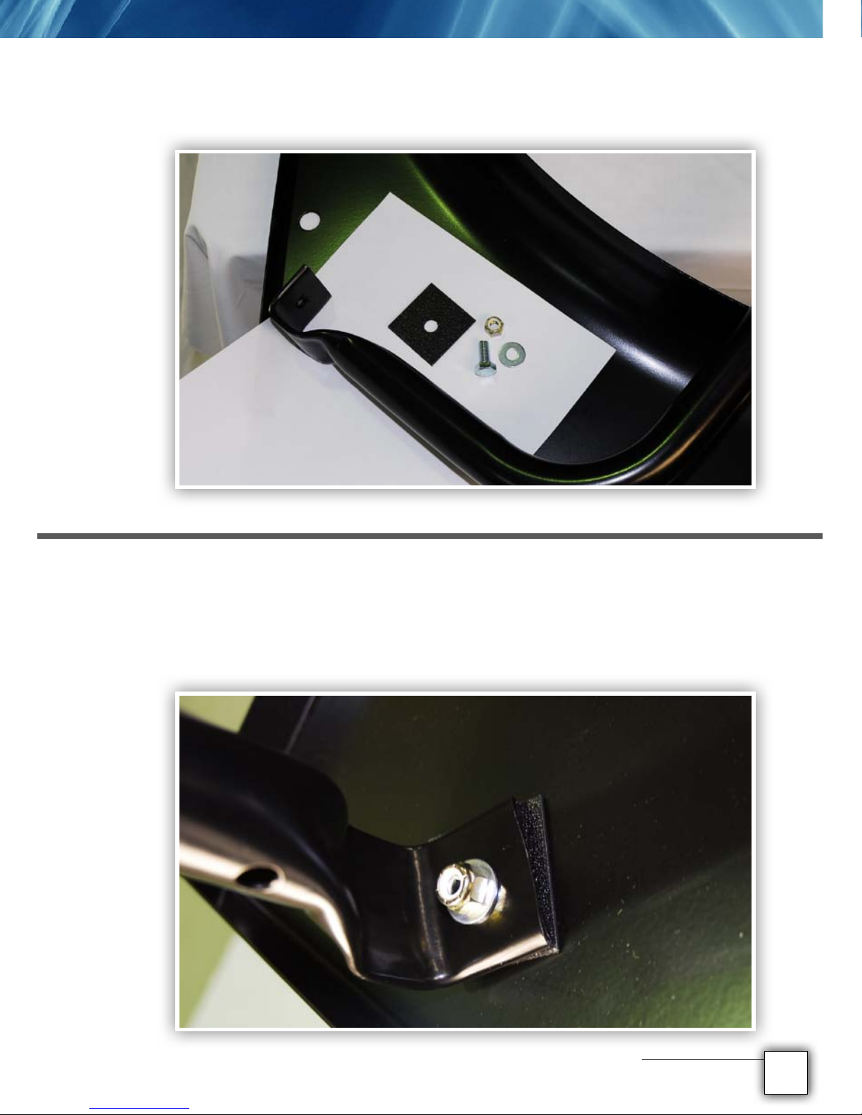
Place the square piece of nylon (spacer) over the hole on the fan shroud
and underneath the foot of the bend bar.
Push the bolt from the underside of the fan shroud, up through the hole, the
nylon spacer and up through the foot of the bend bar. Place the washer over
the bolt and do the nylock nut up nger tight. Let go of the bend bar.
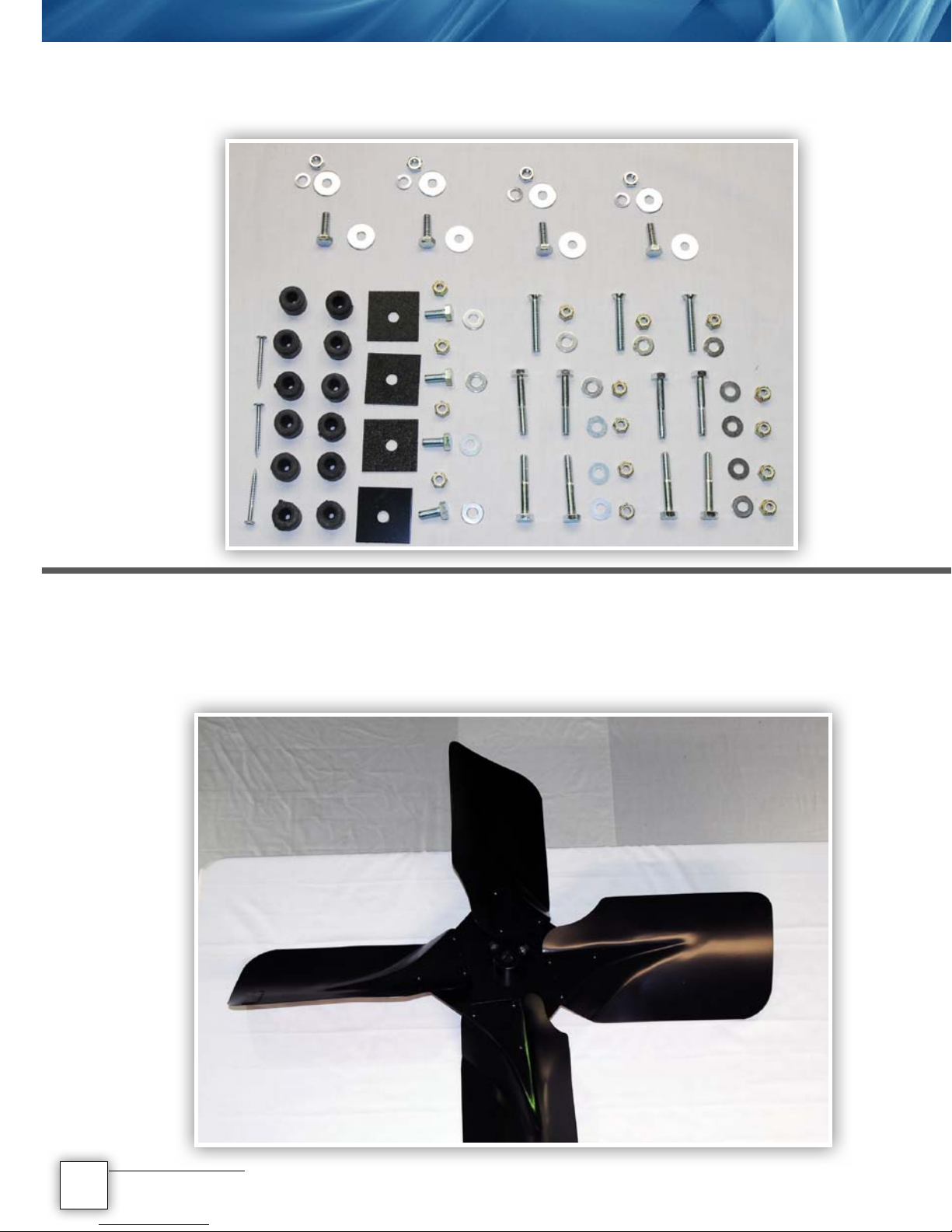
The smallest bolt, a washer and a nylock nut are used to locate the bend
bars into place. A 13mm spanner on both the nut and washer is generally all
that is needed.
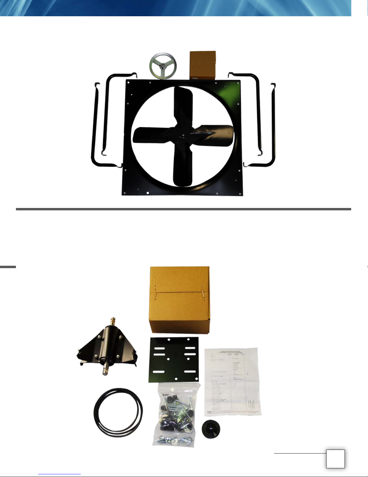
6Fan Assembly 7
Fan Assembly
9
11
10