manuals.online logo
Brands
  1. Home
  2. •
  3. Brands
  4. •
  5. Carrier
  6. •
  7. Air Conditioner
  8. •
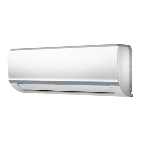
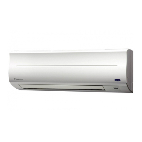
  9. Carrier 42UQV035M User manual

Carrier 42UQV035M User manual

This manual suits for next models

1

Other Carrier Air Conditioner manuals

Carrier G Series User manual

Carrier

Carrier G Series User manual

Carrier 38MVC User manual

Carrier

Carrier 38MVC User manual

Carrier 40VMM007A User manual

Carrier

Carrier 40VMM007A User manual

Carrier 42NL series Manual

Carrier

Carrier 42NL series Manual

Carrier 42QHF009DS seires User manual

Carrier

Carrier 42QHF009DS seires User manual

Carrier 42QZL018DS series User manual

Carrier

Carrier 42QZL018DS series User manual

Carrier Weathermaster 48P2030-100 User guide

Carrier

Carrier Weathermaster 48P2030-100 User guide

Carrier 48PG03---16 Guide

Carrier

Carrier 48PG03---16 Guide

Carrier 42C Series Operation manual

Carrier

Carrier 42C Series Operation manual

Carrier TOSHIBA MMD-UP0241HP-UL User manual

Carrier

Carrier TOSHIBA MMD-UP0241HP-UL User manual

Carrier 50KC*A/B06 Series User manual

Carrier

Carrier 50KC*A/B06 Series User manual

Carrier 48TM007 Instruction Manual

Carrier

Carrier 48TM007 Instruction Manual

Carrier 42TSGS010-703 User manual

Carrier

Carrier 42TSGS010-703 User manual

Carrier 48GC04 Installation and user guide

Carrier

Carrier 48GC04 Installation and user guide

Carrier 40TSV0131UP User manual

Carrier

Carrier 40TSV0131UP User manual

Carrier 38QUS012D8S User manual

Carrier

Carrier 38QUS012D8S User manual

Carrier DC Series User manual

Carrier

Carrier DC Series User manual

Carrier CRECOMZR054B00 User manual

Carrier

Carrier CRECOMZR054B00 User manual

Carrier 51CV/GY User manual

Carrier

Carrier 51CV/GY User manual

Carrier 50FC 08-16 Series Installation and user guide

Carrier

Carrier 50FC 08-16 Series Installation and user guide

Carrier 48/50PG C03-14 Operation manual

Carrier

Carrier 48/50PG C03-14 Operation manual

Carrier 73ACA051T User manual

Carrier

Carrier 73ACA051T User manual

Carrier 50GL-A Instruction Manual

Carrier

Carrier 50GL-A Instruction Manual

Carrier Xpower 40KQM User manual

Carrier

Carrier Xpower 40KQM User manual

Popular Air Conditioner manuals by other brands

Fujitsu ASYG 09 LLCA installation manual

Fujitsu

Fujitsu ASYG 09 LLCA installation manual

York HVHC 07-12DS Installation & owner's manual

York

York HVHC 07-12DS Installation & owner's manual

intensity IDUFCI60KC-3 installation manual

intensity

intensity IDUFCI60KC-3 installation manual

Frigidaire FAC064K7A2 Factory parts catalog

Frigidaire

Frigidaire FAC064K7A2 Factory parts catalog

Sanyo KS2432 instruction manual

Sanyo

Sanyo KS2432 instruction manual

LG MultiV Series installation manual

LG

LG MultiV Series installation manual

CLIMAVENETA a-CHD U-2T 606+2209 OPERATING AND INSTALLATION Manual

CLIMAVENETA

CLIMAVENETA a-CHD U-2T 606+2209 OPERATING AND INSTALLATION Manual

Midea EWK06CW5 user manual

Midea

Midea EWK06CW5 user manual

Pioneer FAB Series installation manual

Pioneer

Pioneer FAB Series installation manual

SPT WA-1511S user manual

SPT

SPT WA-1511S user manual

Mitsubishi Electric Mr.Slim MSZ-A24NA operating instructions

Mitsubishi Electric

Mitsubishi Electric Mr.Slim MSZ-A24NA operating instructions

Mitsubishi Electric PUHZ-RP50VHA4 Service manual

Mitsubishi Electric

Mitsubishi Electric PUHZ-RP50VHA4 Service manual

Panasonic CS-S18HKQ Service manual

Panasonic

Panasonic CS-S18HKQ Service manual

Panasonic CS-E15NKE3 operating instructions

Panasonic

Panasonic CS-E15NKE3 operating instructions

Gree GWH18TC-K3DNA1B/I Service manual

Gree

Gree GWH18TC-K3DNA1B/I Service manual

Friedrich ZoneAire Compact P08SA owner's manual

Friedrich

Friedrich ZoneAire Compact P08SA owner's manual

Daikin R32 Split Series installation manual

Daikin

Daikin R32 Split Series installation manual

Daikin FFQ09Q2VJU Operation manual

Daikin

Daikin FFQ09Q2VJU Operation manual

manuals.online logo
manuals.online logoBrands
  • About & Mission
  • Contact us
  • Privacy Policy
  • Terms and Conditions

Copyright 2025 Manuals.Online. All Rights Reserved.

R410A
FILE NO. SVM-13034
SERVICE MAN AL
SPLIT TYPE
Indoor Unit Outdoor Unit
42UQV035M 38UYV035M
April, 2013
– 1–
CONTENTS
1.SAFETY PRECAUTIONS ............................................................................................. 2
2.SPECIFICATIONS ........................................................................................................ 4
3.REFRIGERANT R410A .................................................................................................. 6
4.CONSTRUCTIONVIEWS ............................................................................................. 14
5.WIRING DIAGRAM....................................................................................................... 16
6.SPECIFICATIONS OF ELECTRICAL PARTS.............................................................. 17
7.REFRIGERANT CYCLE DIAGRAM ............................................................................. 18
8.CONTROL BLOCK DIAGRAM..................................................................................... 20
9.OPERATION DESCRIPTION........................................................................................ 22
10.INSTALLATION PROCEDURE.................................................................................... 45
11.HOWTODIAGNOSETHETROUBLE........................................................................... 60
12.HOWTO REPLACETHE MAIN PARTS....................................................................... 80
13.EXPLODEDVIEWS AND PARTS LIST ........................................................................96
FILE NO. SVM-13034
– 2–
1. SAFETY PRECAUTIONS
For general public use
Power supply cord of outdoor unit shall be more than 1.5 mm2(H07RN-F or 60245IEC66) polychloroprene
sheathed flexible cord.
• Read this “SAFETY PRECAUTIONS” carefully before servicing.
• The precautions described below include the important items regarding safety.Observe them without fail.
• After the servicing work, perform a trial operation to check for any problem.
• Turn off the main power supply switch (or breaker) before the unit maintenance.
CAUTION
New Refrigerant Air Conditioner Installation
• THIS AIR CONDITIONER ADOPTSTHE NEW HFC REFRIGERANT (R410A) WHICH DOES NOT
DESTROY OZONE LAYER.
R410A refrigerant is apt to be affected by impurities such as water, oxidizing membrane, and oils because
the working pressure of R410A refrigerant is approx.1.6 times of refrigerant R22.Accompanied with the
adoption of the new refrigerant, the refrigeration machine oil has also been changed.Therefore, during
installation work, be sure that water, dust, former refrigerant, or refrigeration machine oil does not enter into
the new type refrigerant R410A air conditioner circuit.
To prevent mixing of refrigerant or refrigerating machine oil, the sizes of connecting sections of charging
port on main unit and installation tools are different from those used for the conventional refrigerant units.
Accordingly, special tools are required for the new refrigerant (R410A) units.For connecting pipes, use new
and clean piping materials with high pressure fittings made for R410A only, so that water and/or dust does
not enter. Moreover, do not use the existing piping because there are some problems with pressure fittings
and possible impurities in existing piping.
CAUTION
TO DISCONNECTTHE APPLIANCE FROMTHE MAIN POWER SUPPLY
This appliance must be connected to the main power supply by a circuit breaker or a switch with a contact
separation of at least 3 mm.
DANGER
• ASK AN AUTHORIZED DEALER OR QUALIFIED INSTALLATION PROFESSIONALTO IN-
STALL/MAINTAIN THE AIR CONDITIONER.
INAPPROPRIATE SERVICING MAY RESULT IN WATER LEAKAGE, ELECTRIC SHOCK OR FIRE.
• TURN OFF MAIN POWER SUPPLY BEFORE ATTEMPTING ANY ELECTRICAL WORK. MAKE SURE
ALL POWER SWITCHES ARE OFF.FAILURETO DO SO MAY CAUSE ELECTRIC SHOCK.
DANGER: HIGHVOLTAGE
The high voltage circuit is incorporated.
Be careful to do the check service, as the electric shock may be caused in case of touching parts
on the P.C.board by hand.
• CORRECTLY CONNECT THE CONNECTING CABLE. IF THE CONNECTING CABLE IS INCOR-
RECTLY CONNECTED, ELECTRIC PARTS MAY BE DAMAGED.
• CHECK THAT THE EARTHWIRE IS NOT BROKEN OR DISCONNECTED BEFORE SERVICE AND
INSTALLATION. FAILURE TO DO SO MAY CAUSE ELECTRIC SHOCK.
FILE NO. SVM-13034
–3–
•DO NOT INSTALL NEAR CONCENTRATIONS OF COMBUSTIBLE GAS OR GAS VAPORS. FAILURE
TO FOLLOWTHIS INSTRUCTION CAN RESULT IN FIRE OR EXPLOSION.
•TO PREVENTTHE INDOOR UNIT FROM OVERHEATING AND CAUSING A FIRE HAZARD, PLACE
THE UNIT WELL AWAY (MORE THAN 2 M) FROM HEAT SOURCES SUCH AS RADIATORS, HEAT
REGISTORS, FURNACE, STOVES, ETC.
•WHEN MOVING THE AIR-CONDITIONER FOR INSTALLATION IN ANOTHER PLACE, BE VERY CARE-
FUL NOTTO ALLOW THE SPECIFIED REFRIGERANT (R410A) TO BECOME MIXEDWITH ANY
OTHER GASEOUS BODY INTOTHE REFRIGERATION CIRCUIT. IF AIR OR ANY OTHER GAS IS
MIXED INTHE REFRIGERANT, THE GAS PRESSURE INTHE REFRIGERATION CIRCUIT WILL
BECOME ABNORMALLY HIGH AND IT MAY RESULT IN THE PIPE BURSTING AND POSSIBLE PER-
SONNEL INJURIES.
•IN THE EVENTTHAT THE REFRIGERANT GAS LEAKS OUT OFTHE PIPE DURING THE SERVICE
WORK ANDTHE INSTALLATION WORK, IMMEDIATELY LET FRESH AIR INTO THE ROOM. IFTHE
REFRIGERANT GAS IS HEATED, SUCH AS BY FIRE, GENERATION OF POISONOUS GAS MAY
RESULT.
WARNING
•Never modify this unit by removing any of the safety guards or bypass any of the safety interlock
switches.
•Do not install in a place which cannot bear the weight of the unit. Personal injury and property
damage can result if the unit falls.
•After the installation work, confirm that refrigerant gas does not leak.
If refrigerant gas leaks into the room and flows near a fire source, such as a cooking range, noxious gas
may generate.
•The electrical work must be performed by a qualified electrician in accordance with the Installation
Manual. Make sure the air conditioner uses an exclusive circuit.
An insufficient circuit capacity or inappropriate installation may cause fire.
•When wiring, use the specified cables and connect the terminals securely to prevent external
forces applied to the cable from affecting the terminals.
•Be sure to provide grounding.
Do not connect ground wires to gas pipes, water pipes, lightning rods or ground wires for telephone cables.
•Conform to the regulations of the local electric company when wiring the power supply.
Inappropriate grounding may cause electric shock.
CAUTION
•Exposure of unit to water or other moisture before installation may result in an electrical short.
Do not store in a wet basement or expose to rain or water.
•Do not install in a place that can increase the vibration of the unit.Do not install in a place that can amplify
the noise level of the unit or where noise or discharged air might disturb neighbors.
•To avoid personal injury, be careful when handling parts with sharp edges.
•Perform the specified installation work to guard against an earthquake.
If the air conditioner is not installed appropriately, accidents may occur due to the falling unit.
For Reference:
If a heating operation would be continuously performed for a long time under the condition that the outdoor
temperature is 0°C or lower, drainage of defrosted water may be difficult due to freezing of the bottom plate,
resulting in a trouble of the cabinet or fan.
It is recommended to procure an antifreeze heater locally for a safe installation of the air conditioner.
For details, contact the dealer.
FILE NO. SVM-13034
2. SPECIFICATIONS
–4–
Unit model Indoor 42UQV035M
Outdoor 38UYV035M
Cooling capacity (kW) 3.5
Cooling capacity range (kW) 1.1-3.9
Heating capacity (kW) 4.2
Heating capacity range (kW) 0.9-4.9
Power supply 1Ph/50Hz/220-240V, 1Ph/60Hz/220-230V
Electric Indoor Operation mode Cooling Heating
characteristic Running current (A) 0.21-0.19 0.24-0.22
Power consumption (W) 35 40
Power factor (%) 76 76
Outdoor Operation mode Cooling Heating
Running current (A) 5.00-4.59 5.26-4.82
Power consumption (W) 1055 1110
Power factor (%) 9696
Operating Indoor High (Cooling/Heating) (dB-A) 40/41
noise Medium (Cooling/Heating) (dB-A) 34/35
Low (Cooling/Heating) (dB-A) 27/29
Outdoor (Cooling/Heating) (dB-A) 48/50
Indoor unit Unit model 42UQV035M
Dimension Height (mm) 275
Width (mm) 790
Depth (mm) 235
Net weight (kg) 10
Fan motor output (W) 20
Air flow rate (Cooling/Heating) (m3/min) 9.5/10.4
Outdoor unit Unit model 38UYV035M
Dimension Height (mm) 550
Width (mm) 780
Depth (mm) 290
Net weight (kg) 33
Compressor Motor output (W) 750
Type Single rotary type with DC-inverter variable speed control
Model DA89X1C-23FZ2
Fan motor output (W) 43
Air flow rate (Cooling/Heating) (m3/min) 37.5/37.5
Piping Type Flare connection
connection Indoor unit Liquid side (mm) ∅6.35
Gas side (mm) ∅9.52
Outdoor unit Liquid side (mm) ∅6.35
Gas side (mm) ∅9.52
Maximum length (m) 20
Maximum chargeless length (m) 15
Maximum height difference (m) 10
Refrigerant Name of refrigerant R410A
Weight (kg) 0.80
Wiring Power supply 3 Wires:includes earth (Outdoor)
connection Interconnection 4 Wires:includes earth
Usable temperature range Indoor (Cooling/Heating) (°C) 21-32/0-28
Outdoor (Cooling/Heating) (°C) -10-46/-15-24
* The specifications may be subject to change without notice for purpose of improvement.
2-1. Specifications
COP 3.21/3.65
FILE NO. SVM-13034
2-2. OperationCharacteristic Curve
–5 –
<Cooling> <Heating>
2-3. Capacity Variation Ratio According to Temperature
<Cooling>
50
55
60
65
70
75
80
85
90
95
100
105
32 33 34 35 36 37 38 39 40 41 42 43 44 45 46
Outdoor temp. (℃)
Capacity ratio (%)
Conditions
Indoor:DB27℃/WB19℃
Indoor air flow:High
Pipe length:5m
<Heating>
0
20
40
60
80
100
120
-15 -10 -5 0 5 10
Outdoor temp. (℃)
Heating Capacity ratio (%)
Condition
Indoor:DB20℃
Indoor air flow:High
Pipe length:5m
Capacity ratio 100% is 4.2kw
Capacity ratio 100% is 3.5kw
Voltage : 230V
Voltage : 230V
0
1
2
3
4
5
6
7
8
0 102030405060708090100110120
Compressor Speed (rps)
Current (A)
0
1
2
3
4
5
6
7
8
0 102030405060708090100110120
Compressor Speed (rps)
Current (A)
Conditions
Indoor : DB 27oC/WB 19oC
Outdoor : DB 35oC
A
ir Flow : High
PipeLength : 5m
Voltage : 230
V
Conditions
Indoor : DB 20oC
Outdoor : DB 7oC/WB 6oC
A
ir Flow : High
PipeLength : 5m
Voltage : 230
V
FILE NO. SVM-13034
–6–
3. REFRIGERANT R410A
This air conditioner adopts the new refrigerant HFC
(R410A) which does not damage the ozone layer.
The working pressure of the new refrigerant R410A
is 1.6 times higher than conventional refrigerant
(R22). The refrigerating oil is also changed in
accordance with change of refrigerant, so be careful
that water, dust, and existing refrigerant or refrigerat-
ing oil are not entered in the refrigerant cycle of the
air conditioner using the new refrigerant during
installation work or servicing time.
The next section describes the precautions for air
conditioner using the new refrigerant. Conforming to
contents of the next section together with the
general cautions included in this manual, perform
the correct and safe work.
3-1. Safety During Installation/Servicing
As R410A’s pressure is about 1.6 times higher than
that of R22, improper installation/servicing may
cause a serious trouble. By using tools and materi-
als exclusive for R410A, it is necessary to carry out
installation/servicing safely while taking the following
precautions into consideration.
1. Never use refrigerant other than R410A in an air
conditioner which is designed to operate with
R410A.
If other refrigerant than R410A is mixed, pressure
in the refrigeration cycle becomes abnormally
high, and it may cause personal injury, etc.by a
rupture.
2. Confirm the used refrigerant name, and use tools
and materials exclusive for the refrigerant R410A.
The refrigerant name R410A is indicated on the
visible place of the outdoor unit of the air condi-
tioner using R410A as refrigerant. To prevent
mischarging, the diameter of the service port
differs from that of R22.
3. If a refrigeration gas leakage occurs during
installation/servicing, be sure to ventilate fully.
If the refrigerant gas comes into contact with fire,
a poisonous gas may occur.
4. When installing or removing an air conditioner, do
not allow air or moisture to remain in the refrig-
eration cycle. Otherwise, pressure in the refrig-
eration cycle may become abnormally high so
that a rupture or personal injury may be caused.
5. After completion of installation work, check to
make sure that there is no refrigeration gas
leakage.
If the refrigerant gas leaks into the room, coming
into contact with fire in the fan-driven heater,
space heater, etc., a poisonous gas may occur.
6. When an air conditioning system charged with a
large volume of refrigerant is installed in a small
room, it is necessary to exercise care so that,
even when refrigerant leaks, its concentration
does not exceed the marginal level.
If the refrigerant gas leakage occurs and its
concentration exceeds the marginal level, an
oxygen starvation accident may result.
7. Be sure to carry out installation or removal
according to the installation manual.
Improper installation may cause refrigeration
trouble, water leakage, electric shock, fire, etc.
8. Unauthorized modifications to the air conditioner
may be dangerous. If a breakdown occurs
please call a qualified air conditioner technician
or electrician.
Improper repair’s may result in water leakage,
electric shock and fire, etc.
3-2. Refrigerant Piping Installation
3-2-1. Piping Materials and Joints Used
For the refrigerant piping installation, copper pipes
and joints are mainly used. Copper pipes and joints
suitable for the refrigerant must be chosen and
installed. Furthermore, it is necessary to use clean
copper pipes and joints whose interior surfaces are
less affected by contaminants.
1. Copper Pipes
It is necessary to use seamless copper pipes
which are made of either copper or copper alloy
and it is desirable that the amount of residual oil
is less than 40 mg/10 m. Do not use copper
pipes having a collapsed, deformed or discolored
portion (especially on the interior surface).
Otherwise, the expansion valve or capillary tube
may become blocked with contaminants.
As an air conditioner using R410A incurs pres-
sure higher than when using R22, it is necessary
to choose adequate materials.
Thicknesses of copper pipes used with R410A
are as shown inTable 3-2-1. Never use copper
pipes thinner than 0.8 mm even when it is
available on the market.
FILE NO. SVM-13034
–7–
Table 3-2-1 Thicknesses of annealed copper pipes
Nominal diameter
1/4
3/8
1/2
5/8
Outer diameter (mm)
6.35
9.52
12.70
15.88
Thickness (mm)
R410A R22
0.80 0.80
0.80 0.80
0.80 0.80
1.00 1.00
2. Joints
For copper pipes, flare joints or socket joints are used.Prior to use, be sure to remove all contaminants.
a) Flare Joints
Flare joints used to connect the copper pipes cannot be used for pipings whose outer diameter exceeds
20 mm.In such a case, socket joints can be used.
Sizes of flare pipe ends, flare joint ends and flare nuts are as shown inTables 3-2-3 to 3-2-6 below.
b) Socket Joints
Socket joints are such that they are brazed for connections, and used mainly for thick pipings whose
diameter is larger than 20 mm.
Thicknesses of socket joints are as shown inTable 3-2-2.
Table 3-2-2 Minimum thicknesses of socket joints
Nominal diameter
1/4
3/8
1/2
5/8
Reference outer diameter of
copper pipe jointed (mm)
6.35
9.52
12.70
15.88
Minimum joint thickness
(mm)
0.50
0.60
0.70
0.80
3-2-2. Processing of Piping Materials
When performing the refrigerant piping installation, care should be taken to ensure that water or dust does not
enter the pipe interior, that no other oil than lubricating oils used in the installed air-water heat pump is used,
and that refrigerant does not leak. When using lubricating oils in the piping processing, use such lubricating oils
whose water content has been removed. When stored, be sure to seal the container with an airtight cap or any
other cover.
1. Flare processing procedures and precautions
a) Cutting the Pipe
By means of a pipe cutter, slowly cut the pipe so that it is not deformed.
b) Removing Burrs and Chips
If the flared section has chips or burrs, refrigerant leakage may occur.
Carefully remove all burrs and clean the cut surface before installation.
c) Insertion of Flare Nut
FILE NO. SVM-13034
–8–
A
ØD
d) Flare Processing
Make certain that a clamp bar and copper
pipe have been cleaned.
By means of the clamp bar, perform the flare
processing correctly.
Use either a flare tool for R410A or conven-
tional flare tool.
Flare processing dimensions differ according
to the type of flare tool. When using a con-
ventional flare tool, be sure to secure“dimen-
sion A”by using a gauge for size adjustment. Fig. 3-2-1 Flare processing dimensions
Table 3-2-3 Dimensions related to flare processing for R410A
Nominal
diameter
1/4
3/8
1/2
5/8
Outer
diameter
(mm)
6.35
9.52
12.70
15.88
Thickness
(mm)
0.8
0.8
0.8
1.0
A (mm)
Flare tool for R410A
clutch type
0 to 0.5
0 to 0.5
0 to 0.5
0 to 0.5
Conventional flare tool
Clutch type Wing nut type
1.0 to 1.5 1.5 to 2.0
1.0 to 1.5 2.0 to 2.5
Table 3-2-4 Dimensions related to flare processing for R22
Nominal
diameter
1/4
3/8
1/2
5/8
Outer
diameter
(mm)
6.35
9.52
12.70
15.88
Thickness
(mm)
0.8
0.8
0.8
1.0
A (mm)
Flare tool for R22
clutch type
0 to 0.5
0 to 0.5
0 to 0.5
0 to 0.5
Conventional flare tool
Clutch type Wing nut type
0.5 to 1.0 1.0 to 1.5
0.5 to 1.0 1.5 to 2.0
Table 3-2-5 Flare and flare nut dimensions for R410A
Nominal
diameter
1/4
3/8
1/2
5/8
Outer diameter
(mm)
6.35
9.52
12.70
15.88
Thickness
(mm)
0.8
0.8
0.8
1.0
Dimension (mm)
ABCD
9.1 9.2 6.5 13
13.2 13.5 9.7 20
16.6 16.0 12.9 23
19.7 19.0 16.0 25
Flare nut width
(mm)
17
22
26
29
FILE NO. SVM-13034
–9–
43˚ to 45˚
45˚ to 46˚
B A CD
Table 3-2-6 Flare and flare nut dimensions for R22
Nominal
diameter
1/4
3/8
1/2
5/8
3/4
Outer diameter
(mm)
6.35
9.52
12.70
15.88
19.05
Thickness
(mm)
0.8
0.8
0.8
1.0
1.0
Dimension (mm)
ABCD
9.0 9.2 6.5 13
13.0 13.5 9.7 20
16.2 16.0 12.9 20
19.7 19.0 16.0 23
23.3 24.0 19.2 34
Flare nut width
(mm)
17
22
24
27
36
Fig. 3-2-2 Relations between flare nut and flare seal surface
2. Flare Connecting Procedures and Precautions
a) Make sure that the flare and union portions do not have any scar or dust, etc.
b) Correctly align the processed flare surface with the union axis.
c) Tighten the flare with designated torque by means of a torque wrench. The tightening torque for R410A is
the same as that for conventional R22. Incidentally, when the torque is weak, the gas leakage may occur.
When it is strong, the flare nut may crack and may be made non-removable. When choosing the tighten-
ing torque, comply with values designated by manufacturers.Table 3-2-7 shows reference values.
NOTE :
When applying oil to the flare surface, be sure to use oil designated by the manufacturer.
If any other oil is used, the lubricating oils may deteriorate and cause the compressor to burn out.
Table 3-2-7 Tightening torque of flare for R410A [Reference values]
Nominal
diameter
1/4
3/8
1/2
5/8
Outer diameter
(mm)
6.35
9.52
12.70
15.88
Tightening torque
N•m (kgf•cm)
14 to 18 (140 to 180)
33 to 42 (330 to 420)
50 to 62 (500 to 620)
63 to 77 (630 to 770)
Tightening torque of torque
wrenches available on the market
N•m (kgf•cm)
16 (160), 18 (180)
42 (420)
55 (550)
65 (650)
FILE NO. SVM-13034