manuals.online logo
Brands
  1. Home
  2. •
  3. Brands
  4. •
  5. Carrier
  6. •
  7. Air Conditioner
  8. •
  9. Carrier Infinity 48DU-030 User manual

Carrier Infinity 48DU-030 User manual

This manual suits for next models

5

Other Carrier Air Conditioner manuals

Carrier 42C Series Operation manual

Carrier

Carrier 42C Series Operation manual

Carrier Comfort 48VL-E User manual

Carrier

Carrier Comfort 48VL-E User manual

Carrier 48AJ Service manual

Carrier

Carrier 48AJ Service manual

Carrier 42S Series User manual

Carrier

Carrier 42S Series User manual

Carrier 50PG20-28 User guide

Carrier

Carrier 50PG20-28 User guide

Carrier N4A4 User manual

Carrier

Carrier N4A4 User manual

Carrier 50BA Dimensions and installation guide

Carrier

Carrier 50BA Dimensions and installation guide

Carrier 42QZA018DS-1 User manual

Carrier

Carrier 42QZA018DS-1 User manual

Carrier 40MBDQ series User manual

Carrier

Carrier 40MBDQ series User manual

Carrier OMNIZONE 50XJ064-104 User manual

Carrier

Carrier OMNIZONE 50XJ064-104 User manual

Carrier 38EZG Instructions and recipes

Carrier

Carrier 38EZG Instructions and recipes

Carrier 48HE003---006 User manual

Carrier

Carrier 48HE003---006 User manual

Carrier CRECOMZR054B00 User manual

Carrier

Carrier CRECOMZR054B00 User manual

Carrier 48JCH 04-06 Series Installation and user guide

Carrier

Carrier 48JCH 04-06 Series Installation and user guide

Carrier 40MBD-06SI User manual

Carrier

Carrier 40MBD-06SI User manual

Carrier PA3Z-B User manual

Carrier

Carrier PA3Z-B User manual

Carrier 48KHA Dimensions and installation guide

Carrier

Carrier 48KHA Dimensions and installation guide

Carrier 24ACA User manual

Carrier

Carrier 24ACA User manual

Carrier 42SIC Manual

Carrier

Carrier 42SIC Manual

Carrier 42NH - CLZ Manual

Carrier

Carrier 42NH - CLZ Manual

Carrier 48HC*04-14 Installation and user guide

Carrier

Carrier 48HC*04-14 Installation and user guide

Carrier Performance 15 48VR-A Instruction Manual

Carrier

Carrier Performance 15 48VR-A Instruction Manual

Carrier 00EFN900044000A User manual

Carrier

Carrier 00EFN900044000A User manual

Carrier 42UQV025M Series User manual

Carrier

Carrier 42UQV025M Series User manual

Popular Air Conditioner manuals by other brands

Fujitsu ASYG 09 LLCA installation manual

Fujitsu

Fujitsu ASYG 09 LLCA installation manual

York HVHC 07-12DS Installation & owner's manual

York

York HVHC 07-12DS Installation & owner's manual

intensity IDUFCI60KC-3 installation manual

intensity

intensity IDUFCI60KC-3 installation manual

Frigidaire FAC064K7A2 Factory parts catalog

Frigidaire

Frigidaire FAC064K7A2 Factory parts catalog

Sanyo KS2432 instruction manual

Sanyo

Sanyo KS2432 instruction manual

LG MultiV Series installation manual

LG

LG MultiV Series installation manual

CLIMAVENETA a-CHD U-2T 606+2209 OPERATING AND INSTALLATION Manual

CLIMAVENETA

CLIMAVENETA a-CHD U-2T 606+2209 OPERATING AND INSTALLATION Manual

Midea EWK06CW5 user manual

Midea

Midea EWK06CW5 user manual

Pioneer FAB Series installation manual

Pioneer

Pioneer FAB Series installation manual

SPT WA-1511S user manual

SPT

SPT WA-1511S user manual

Mitsubishi Electric Mr.Slim MSZ-A24NA operating instructions

Mitsubishi Electric

Mitsubishi Electric Mr.Slim MSZ-A24NA operating instructions

Mitsubishi Electric PUHZ-RP50VHA4 Service manual

Mitsubishi Electric

Mitsubishi Electric PUHZ-RP50VHA4 Service manual

Panasonic CS-S18HKQ Service manual

Panasonic

Panasonic CS-S18HKQ Service manual

Panasonic CS-E15NKE3 operating instructions

Panasonic

Panasonic CS-E15NKE3 operating instructions

Gree GWH18TC-K3DNA1B/I Service manual

Gree

Gree GWH18TC-K3DNA1B/I Service manual

Friedrich ZoneAire Compact P08SA owner's manual

Friedrich

Friedrich ZoneAire Compact P08SA owner's manual

Daikin R32 Split Series installation manual

Daikin

Daikin R32 Split Series installation manual

Daikin FFQ09Q2VJU Operation manual

Daikin

Daikin FFQ09Q2VJU Operation manual

manuals.online logo
manuals.online logoBrands
  • About & Mission
  • Contact us
  • Privacy Policy
  • Terms and Conditions

Copyright 2025 Manuals.Online. All Rights Reserved.

Turn to the Expertd
Installation Instructions
IMPORTANT: OAT sensor must be field installed. See
Accessory Installation for more details.
IMPORTANT: This Infinity _unit is designed for use with an
Infinity User Interface.
NOTE: Read the entire instruction manual before starting the
installation.
TABLE OF CONTENTS
Page
SAFETY CONSIDERATIONS ........................ 2
INTRODUCTION .................................. 2
RECEIVING AND INSTALLATION ................ 2-12
Check Equipment ................................. 2
Identify Unit ................................... 2
Inspect Shipment ................................ 2
Provide Unit Support .............................. 2
Roof Curb ..................................... 2
Slab Mount .................................... 2
Ground Mount ................................. 2
Provide Clearances ................................ 7
Rig and Place Unit ................................ 7
Inspection ..................................... 8
Introduction .................................... 8
Use of Rigging Bracket ........................... 8
Select and Install Ductwork .......................... 8
Converting Horizontal Discharge Units to Downflow
(Vertical) Discharge Units ......................... 9
Provide for Condensate Disposal .................... 10
Install Flue Hood ................................. 10
Install Gas Piping ................................ 10
Install Electrical Connections ....................... 11
High- Voltage Connections ....................... 11
Routing Power Leads Into Unit .................... 12
Connecting Ground Lead to Ground Screw . ......... 12
Routing Control Power Wires .................... 12
Accessory Installation ........................... 12
Special Procedures for 208-v Operation ............. 12
PRE-START-UP .................................. 15
START-UP .................................... 15-25
Unit Start-Up and Troubleshooting .................. 15
Sequence of Operation ......................... 19-24
Check for Refrigerant Leaks ........................ 24
Start-Up Adjustments ............................. 24
Checking Cooling and Heating Control Operation ..... 25
Checking and Adjusting Refrigerant Charge .......... 25
Refrigerant Charge ............................. 25
No Charge .................................... 25
Low Charge Cooling ............................ 25
To Use Cooling Charging (;harts ................... 25
Non-Comnmnicating Emergency Cooling/Heating Mode . 25
MAINTENANCE ............................... 27-29
Air Filter ....................................... 27
Indoor Fan and Motor ............................. 27
Inducer Blower .................................. 27
Limit Switch .................................... 27
C99001
Fig. 1 - Unit 48DU
Burner Ignition .................................. 27
Main Burners ................................... 27
Inducer Pressure Switch ........................... 27
Outdoor Coil. Indoor Coil, and Condensate Drain Pan .... 28
Outdoor Fan .................................... 28
Electrical Controls and Wiring ...................... 28
Refrigerant Circuit ................................ 28
Indoor Airflow . ................................. 28
Pressure Switches ................................ 28
Loss-of-Charge Switch ........................... 28
High-Pressure Switches ........................... 28
Copeland Scroll Compressor (Puron _: Refrigerant) ....... 29
Refrigerant System ............................... 29
Refrigerant ................................... 29
Compressor Oil ................................ 29
Servicing Systems on Roofs with Synthetic Materials ... 29
Liquid-Line Filter Drier ......................... 29
Puron (R-410A) Refrigerant Charging .............. 29
TROUBLESHOOTING .......................... 29-31
FINAL CHECKS .................................. 31
CARE AND MAINTENANCE ....................... 31
START-UP CHECKLIST ........................... 35
SAFETY CONSIDERATIONS
Installation and servicing of this equipment can be hazardous due to
mechanical and electrical components. Only trained and qualified
personnel should install, repair, or service this equipment.
Untrained personnel can perform basic maintenance functions, such
as cleaning and replacing air filters. All other operations must be
performed by trained service personnel. When working on this
equipment, observe precautions in the literature, on tags, and on
labels attached to or shipped with the unit and other safety
precautions that may apply.
Followallsafetycodes.Installationmustbeincompliancewith
localandnationalbuildingcodes.Wearsafetyglasses,protective
clothing,andworkgloves.Havefireextinguisheravailable.Read
theseinstructionsthoroughlyandfollowallwarningsorcautions
includedinliteratureandattachedtotheunit.
Recognizesafetyinformation.Thisisthesafety-alertsymbol_.
Whenyouseethissymbolontheunitandininstructionsormanuals,
bealerttothepotentialforpersonalinjury.Understandthesesignal
words:DANGER.WARNING,andCAUTION.Thesewordsare
usedwiththesafety-alertsymbol.DANGERidentifiesthemostse-
rioushazardswhichwillresultinseverepersonalinjuryordeath.
WARNINGsignifieshazardswhichcould result in personal injury
or death. CAUTION is used to identify unsafe practices which may
result in minor personal injury or product and property damage.
NOTE is used to highlight suggestions which will result in en-
hanced installation, reliability, or operation.
Always install furnace to operate within the intended temperature
rise range with a duct system which has an external static pressure
within the allowable range, as specified in "Indoor Airflow Adjust-
ments" section of these instructions. See furnace rating plate.
ELECTRICAL SHOCK HAZARD
Failure to follow this warning could result in personal injury
or death.
Before installing or servicing system, always turn off main
power to system. There may be more than one disconnect
switch. Turn off accessory heater power switch if applicable.
UNIT OPERATION AND SAFETY HAZARD
Failure to follow this warning could result in personal injury
or equipment damage.
Puron (R-410A) systems operate at higher pressures than
standard R-22 systems. DO NOT use R-22 service
equipment or components on Puron (R-410A) equipment.
Ensure service equipment is rated for Puron {R-410A).
INTRODUCTION
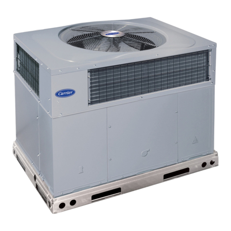
The 48DU packaged unit is a fully self-contained combination
Category I gas heating/electric air conditioner designed for outdoor
installation (See Fig. 1). Standard units are shipped in a
horizontal-discharge configuration for installation on a
ground-level slab or directly on the ground if local codes permit.
Standard units can be converted to downflow (vertical) discharge
configurations for rooftop applications.
Models with an N in the fifth position of the model number are
dedicated Low NOx units designed for California installations.
These models meet the California maximum oxides of nitrogen
(NOx) emissions requirements of 40 nanograms/joule or less as
shipped from the factory and must be installed in California Air
Quality Management Districts or any other regions in North
America where a Low NOx rule exists.
NOTE: Low NOx requirements apply only to natural gas
installations.
RECEIVING AND INSTALLATION
Step 1--Check Equipment
IDENTIFY UNIT
The unit model number and serial number are printed on the unit
informative plate. Check this information against shipping papers.
INSPECT SHIPMENT
Inspect for shipping damage while unit is still on shipping pallet. If
unit appears to be damaged or is torn loose from its anchorage, have
it examined by transportation inspectors before removal. Forward
claim papers directly to transportation company. Manufacturer is
not responsible for any damage incurred in transit. Check all items
against shipping list. Immediately notify the nearest Carrier office
if any item is missing. To prevent loss or damage, leave all parts in
original packages until installation.
Step 2--Provide Unit Support
For hurricane tie downs, contact distributor for details and PE
(Professional Engineering) Certificate, if required.
ROOF CURB
Install accessory roof curb in accordance with instructions shipped
with curb (See Fig. 4). Install insulation, cant strips, roofing, and
flashing. Ductwork must be attached to curb.
IMPORTANT: The gasketing of the unit to the roof curb is critical
for a water tight seal. Install gasketing material supplied with the
roof curb. Improperly applied gasketing also can result in air leaks
and poor unit performance.
Curb should be level to within 1/4 in. (See Fig. 2). This is necessau
for unit drain to function properly. Refer to accessory roof curb
installation instructions for additional information as required.
3MAXIMUMALLOWABLE
DIFFERENCE(in,)
B A-B B-C A-C
1/4 1/4 1/4
C99065
Fig. 2 - Unit Leveling Tolerances
SLAB MOUNT
Place the unit on a solid, level concrete pad that is a minimum of 4
in. thick with 2 in. above grade. The slab should extend
approximately 2 in. beyond the casing on all 4 sides of the unit (See
Fig. 3). Do not secure the unit to the slab except when required by
local codes.
7
EVAR COIl COND COIL
Fig. 3- Slab Mounting Detail
C99096
GROUND MOUNT
The unit may be installed either on a slab or placed directly on the
ground if local codes permit. Place the unit on level ground prepared
with gravel for condensate discharge.
Roof Curb for Small Cabinet
Note A: When unit mounting screw is used,
retainer bracket must also be used,
Roof Curb for Large Cabinet
Note A: When unit mounting screw is used,
retainer bracket must also be used,
UNIT SIZE
024-030
036-060
E
Long
Support
Support
A
R/A
\\\\\
_Gasket around _
duct
S/A
/2
/
insulated
deck pan Gasket around
outer edge \ \
\\,\
NOTES:
ODS CATALOG A B
NUMBER IN. (MM) IN. (MM)
CPRFCURB008A00 8 (203) 11 (279)
CPRFCURB00FA00 14 (356) 11 (279)
CPRFCURB008A00 8 (203) 16-3/16 (411)
CPRFCURB009A00 14 (356) 16-3/16 (411)
[. Roof curb must be set up for unit being installed.
C
IN. (MM)
16-1/2 (419)
16-1/2 (419)
17-3/8 (441)
17-3/8 (441)
D
IN. (MM)
28-3/4 (730)
28-3/4 (730)
40-1/4 (1022)
40-1/4 (1022)
E
IN. (MM)
30-3/8 (771)
30-3/8 (771)
41-15/16 (1065)
41-15/16 (1065)
F
IN. (MM)
44-5/16 (1126)
44-5/16 (1126)
44-7/16 (1129)
44-7/16 (1129)
A05308
G
IN. (MM)
45-15/16 (1167)
45-15/16 (1167)
46 - 1/16 (1169)
46-1/16 (1169)
2. Seat strip must be applied, as required, to unit being installed.
3. Dimensions are in inches.
4. Dimension in ( )are in millimeters.
5. Roof curb is made of 16 gauge steel.
6. Attach ductwork to curb (flanges of duct rest on curb).
7. Inadated panels: I in. thick fiberglass 1 lb. density.
S. When unit mounting screw is used (see Note A). a retainer bracket must be used as well. This bracket must also be used when required by code for hurricane or seismic
conditions. This bracket is available through Micrometl.
Fig. 4 - Roof Curb Dimensions
@NT............. l
i TCIfO0 S / _ N t _ il )"0 W i i jl i !, sk] !F A f_!I,B _J: OR
j tIER s o oR l;_ s _i,_ ors{, .... _ .......
t
_°
D
18Dl,{ 24o ¢o
TOP VIEW EI_EJS Dins i_ i] @REz zJ is
o>
o_
5 5
{3 44]
FYFiD DITAY
SERJ][{: PORTS
] 5 9 _ il6 3
[0 90i
!
/
/
4 COMPI!_5SOI, IIOW[R GAS S{CiiO_
& EL[¢!R:¢AL ACOESS PANEL
............................ 1126 i ...........................
[4! 78]
Z8 6 [I 13) OL# i( 0--
i0_11 liNI Rf ,
i {O_ROL [NTR_¸ , ,
iis,,
i
i !'%
LEFT SIDE VIEW FRONTVIEW
i ,,,, _'_ _i i
{ 8 + _ /_/{c_/I Pi I !1i i
11 8,] 6_s EITII
[: i;ii i ;' =......
I _ ....... 49 6
11 81! 13 831 [21 6_1 [9 83]
RIGHTSIDE VIEW REAR VIEW
L8 LI] 2s,4 O30
SZlS_[ -_,s ELL ! 8 ¢OC,LII6 _ I 8_'S IA ,iSB,USO[ 084
I
_t
_°
TOP ViEW
805
i 13 i_;
c
cI c_ rli 'i,i ur T !OT c[_i; o ,3 ,T MM r
U[/ k! CIRISIiC3 [17_-[ _ _ ; T v i
DU i,r :8, I , 1: j :( I: I :, )i , 4 , I,, ::
: • :
_ DL0420_ 8O i ,3 5 122 , ';3 4_, 3 ,I;_1 =n _ ,2 ,,16 :
6[,i13_: 1"_ 8:( i q [23 6 _,,(, 4 / q o : _ (/
8111, ogp 8 , I [ / : _ 14 _; ,9 19 [ _ I ,,
!....................................................... ......................................
, 8 8 ' ,_s , g r, a '9 8 }4T 18 {
_ DL04813, 28'3, I i] 51 [23_ i 3 l,( 4939 59 8( 3 /57 ,18 O
[ _ 8,' O i 12 9_ 4/ 0 ,,,' (/
I111:6,/I_ 8 O I ) ! [ -_ } 4 H f i i 81 i 4, o 1 _ :)
.....!! ................LI , ..................
C©R!ER _,EI HT L_S gR{(SU_R_3CLeARANCeS TO CO_._SIIBL_ MAI%,
! I r
O38O5O ji00/45 4
O38O9O ji01/45 B
042050 ji11150 3
,04_090 ji13/51 5
04_I_0 ji15/52 2
0_09_ ji26/5_ 2
i
0_11_ ji2_'_,_ 2
i
O_l_O ji26;_,_ 2
1 _o I 91 41 i;'87
i, / I 9 41 r 1'8 [
,lls8 i 182'8
1 II e 4202'si
:iiiiiii!ii;ii
LI EIEIS 14:
181 OI Lq ? 5b { Ill OO}
SiO£ OPPOS_T[ BkrTS 355 _ [i¢ 00:
I_OllOr40I ¸ UN_ ,2 tlO 5O ¸,
_C. R_F_B CLB_RAr_&
I_( I_E_J U_UTS P{;_'E_ _JiR, ¸ S]i)E i05_ 8 14_ 00}
@_IT A_D LI_GRSL'_I_EDSURFACES PO_ER ENTR_ ._Z0E q 4 0 [}_ 00}
R_Q_R_ CL_ARANC_ FOR (_I_AT[O_ AND _J_VlClNG _f_ LTME/ER5 _l _4:,
_? (:.,K A(:¢ESS 8i[)[ 914 0 136 0D}
{EXCEPT FOR NE: 9E,_IZ_E_JiS_
_K/i ],:P 91¸¸1 0 136 ,)8:,
.qT_ C'PP¢'S_i_ r;U_TS 911 0 13_ 00}
8UCT PA_[i 5O4 _ [i_ 00]_
S _T_:_4 I_{'_ S¸STEM PERFORI,O[_¢__'8; ¢O41_ROITS[_
o>
o_
s
UNIT SIZE
NOMINAL CAPACITY (ton)
OPERATING WEIGHT 0b,)
COMPRESSORS
Quantity
REFmGERANT: PURON (R-410A)
Quantity (lb.)
REFRIGERANT METERING DEVICE
Size
Part Number
OUTDOOR COiL
Rows.Sins/in.
Face Area (sq ft)
OUTDOOR FAN
Nominal Cfm
Diameter (in,)
Motor Hp (Rpm)
INDOOR COiL
Rows..,Fins/in.
Face Area (sq ft)
INDOOR FAN
Nominal Airflow (Cfm)
Comfort
Efficiency
Max
Furnace (gas ht,) airflow-Low Stage
Furnace (gas ht,) airflow-High Stage
Size (in,)
Motor HP (RPM)
FURNACE SECTION*
Burner Orifice No, (Qty,.,Drill Size)
Natural Gas
HiGH =PRESSURE SWITCH (peig)
Cut-out
Reset (Auto)
HIGH=PRESSURE SWITCH 2 (psi9)
(Compressor Solenoid)
Cut-out
Reset (Auto)
LOSS-OF-CHARGE /
LOW-PRESSURE SWITCH
(Liquid Lh_e) (psig)
Cut-out
Reset (auto)
RETURN=AIR FILTERS (in.)1-
Throwaway
Contimled next page,
Table 1--Physical Data - Unit 48DU
024040 024060 030040 030060 036060 036090 042060 042090
2 2 2-1/2 2-1/2 3 3 3-1/2 3-1/2
398 401 403 408 485 493 507 515
2-Stage Scroll
10.1 10.1 11.3 11.3 9,5 9,5 13.8 13.8
TXV
2Ton 2Ton 3Ton 3Ton 3Ton 3Ton 4Ton 4Ton
EA36YD129 EA36YD129 EA36YD139 EA36YD139 EA36YD139 EA36YD139 EA36YD149 EA36YD149
2.,,21 2.,,21 2.,,21 2.,,21 2.,,21 2.,,21 2.,,21 2.,,21
13.8 13.8 15.3 15.3 17.5 17.5 19.4 19.4
2700 2700 2700 2700 2800 2800 2800 2800
22 22 22 22 22 22 22 22
I/8 (825) I/8 (825) I/8 (825) I/8 (825) I/8 (825) I/8 (825) I/8 (825) I/8 (825)
3.,,17 3.,,17 3.,,17 3.,,17 3.,,17 3.,,17 3.,,17 3.,,17
3,7 3,7 3,7 3,7 4,7 4,7 4,7 4,7
7OO
8OO
Variable based on Comfort Rollback(see UserlnterMceinstructionsfor moreinformaion).
700 875 875 1050 1050
800 1000 1000 1200 1200
475
844
10x10
1/2
727
1120
10x10
1/2
745
1120
11x10
3/4
875
1410
11x10
3/4
475
844
10xl0
1/2
727
1120
10x10
1/2
1225
1400
745
1120
11x10
3/4
1225
1400
875
1410
11x10
3/4
2.,,44 3.,,44 2.,,44 3.,,44 3.,,44 3.,,38 3.,,44 3.,,38
870 ±10
470 ± 25
585 ±15
455 ±15
25 ± 5
55 ± 5
90x24x1 90x24x1 90x24x1 90x24x1 94x30x1 94x30x1 94x36x1 94x36x1
UNIT SIZE
NOMINAL CAPACITY (ton)
OPERATING WEIGHT (lb.)
COMPRESSORS
Quantity
REFRIGERANT," PURON (R=41OA)
Quantity (lb.)
REFRIGERANT METERING DEVICE
Size
Part Number
OUTDOOR FAN
Nominal Cfm
Diameter (in.)
Motor Hp (Rpm)
OUTDOOR COIL
Rows..,Fins/in.
Face Area (sq ft)
INDOOR COIL
Rows._Fins/in.
Face Area (sq ft)
INDOOR FAN
Nominal Airflow (Cfm)
Comfort
Efficiency
Max
Furnace (gas ht.) airflow-Low Stage
Furnace (gas ht.) airflow-High Stage
Size (In.)
Motor HP (RPM)
FURNACE SECTION*
Burner Orifice No, (Qty,.,DriH Size}
Natural Gas
HmGH-PRESSURE SWITCH (psig)
Cut-out
Reset (Auto)
HmGH=PRESSURE SWITCH 2 (psi9)
(Compressor Solenoid)
Cut-out
Reset (Auto)
LOSS=OF=CHARGE /
LOW=PRESSURE SWITCH
(Liquid Line) (psig)
Cut-out
Reset (auto)
RETURN-AIR FILTERS (in.)f
Throwaway
Based on altitude of 0 to 2000 ft.
Table 1--Physical Data (Can't) - Unit 48DU
048090 048115 048130
4445
521 521 521 572
2-Stage Scroll
1
15.3 15.3 15.3 15.8
TXV
4 Ton 4 Ton 5 Ton
EA36YD149 EA36YD149
060090 060115 080130
5 5
572 572
15.8 15.8
4Ton 5Ton 5Ton
EA36YD149 EA36YD159 EA36YD159 EA36YD159
3300 3300 3300 3300 3300 3300
22 22 22 22 22 22
1/4 (1100) 1/4 (1100) 1/4 (1100) 1/3 (1110) 1/3 (1110) 1/3 (1110)
2,.,21 2._21 2._21 2..,21 2..,21 2...21
19.4 19.4 19.4 23.3 23.3 23.3
3..,17 3.,.17 3.,.17 4..,17 4..,17 4.,.17
5.7 5.7 5.7 5.7 5.7 5.7
Variable based on Comfort Rollback(see Userlnterfaceinstructionsfor moreinformation),
1400 1400 1400 1750
1600 1600 1600 2000
1215
1885
11x10
8/4
1255
1875
11x10
3/4
845
1300
11x10
1
815
1385
11x10
3/4
1750 1750
2000 2000
1215
1910
11x10
1
3...33 3...31
1255
1920
11x10
1
3...38 3...33 3...31 3...38
670 ± 10
470 ± 25
565 ± 15
455 ±15
25 ± 5
55 ± 5
24x36x1 24x36x1 24x36x1 24x38x1 24x36x1 24x36x1
fRequired filter sizes shown are based on the larger of the ARI (Air Conditioning and Refrigeration Institute) rated cooling airflow or the heating airflow velocity of 300 ft/min
ute for throwaway type or 450 ftiminute for high capacity type. Air filter pressure drop for non standard filters illust not exceed 0,08 in, we.
Step 3--Provide Clearances
The required minimum service clearances are shown in Fig. 5 and
6. Adequate ventilation and outdoor air must be provided. The
outdoor fan draws air through the outdoor coil and discharges it
through the top fan grille. Be sure that the fan discharge does not
recirculate to the outdoor coil. Do not locate the unit in either a
corner or under an overhead obstruction. The minimum clearance
under a partial overhang (such as a normal house overhang) is 48 in.
above the unit top. The maximum horizontal extension of a partial
overhang must not exceed 48 in.
IMPORTANT: Do not restrict outdoor airflow. An air restriction at
either the outdoor-air inlet or the fan discharge may be detrimental
to compressor life.
Do not place the unit where water, ice, or snow from an overhang
or roof will damage or flood the unit. Do not install the unit on
carpeting or other combustible materials. Slab-mounted units
should be at least 4 in. above the highest expected water and runoff
levels. Do not use unit if it has been under water.
Step 4_Rig and Place Unit
Rigging and handling of this equipment can be hazardous for many
reasons due to the installation location (roofs, elevated structures.
etc.).
Only trained, qualified crane operators and ground support staff
should handle and install this equipment.
When working with this equipment, observe precautions in the
literature, on tags, stickers, and labels attached to the equipment, and
any other safety precautions that might apply.
Training for operators of the lifting equipment should include, but
not be limited to, the following:
1. Application of the lifter to the load, and adjustment of the
lifts to adapt to various sizes or kinds of loads.
2. Instruction in any special operation or precaution.
3. Condition of the load as it relates to operation of the lifting
kit, such as balance, temperature, etc.
Follow all applicable safety codes. Wear safety shoes and work
gloves.
n
INSPECTION
Prior to initial use, and at monthly intervals, all rigging brackets and
straps should be visually inspected for any damage, evidence of
wear, structural deformation, or cracks. Particular attention should
be paid to excessive wear at hoist hooking points and load support
areas. Brackets or straps showing any kind of wear in these areas
must not be used and should be discarded.
ELECTRICAL SHOCK HAZARD
Failure to follow this warning could result in personal injury
or death.
Befnre installing or servicing system, always turn off main
power to system. There may be more than one disconnect
switch. Turn off accessory heater power switch if applicable.
Tag disconnect switch with a suitable warning label.
UNIT FALLING HAZARD
Failure to fnllow this warning could result in personal injury
or death.
Never stand beneath rigged units or lift over people.
INTRODUCTION
The lifting/rigging bracket is engineered and designed to be
installed only on Small Packaged Products.
This bracket is to be used to rigdift a Small Packaged Product onto
roofs or other elevated structures.
PROPERTY DAMAGE HAZARD
Failure to fnllow this warning could result in personal
injury/death or property damage.
Rigging brackets for one unit use only, When removing a
unit at the end of its useful life, use a new set of brackets.
USE OF RIGGING BRACKET
Field Installation of Ri_in_ Bracket
1. If applicable, remove unit from shipping carton. Leave top
shipping skid on the unit for use as a spreader bar to prevent
the rigging straps from damaging the unit. If the skid is not
available, use a spreader bar of sufficient length to protect the
unit from damage.
2. Remove 4 screws in unit corner posts.
3. Attach each of the 4 metal rigging brackets under the panel
rain lip (See Fig. 7). Use the screws removed in step 2 above
to secure the brackets to the unit.
PROPERTY DAMAGE HAZARD
Failure to fnllow this warning could result in personal
injury/death or property damage.
Rigging bracket MUST be under the rain lip to provkle
adequate lifting.
PROPERTY DAMAGE HAZARD
Failure to follow this warning could result in personal
injury/death or prnperty damage.
Do not strip screws when re-securing the unit. If a screw is
stripped, replace the stripped one with a larger diameter screw
(included).
Ri_in_/Liftin_ of Unit
1. Bend top of brackets down approximately 30 degrees from
the corner posts.
2. Attach straps of equal length to the rigging brackets at
opposite ends of the unit. Be sure straps are rated to hold the
weight of the unit (See Fig. 7).
3. Attach a clevis of sufficient strength in the middle of the
straps. Adjust the clevis location to ensure unit is lifted level
with the ground.
4. After unit is securely in place detach rigging straps. Remove
corner posts, screws, and rigging brackets then reinstall
screws.
UNIT FALLING HAZARD
Failure to follow this warning could result in personal
injury/death or property damage.
When straps are taut, the clevis should be a minimum of 36
inches above the unit top cover.
After the unit is placed on the roof curb or mounting pad, remove
the top crating.
Step 5--Select and Install Ductwork
The design and installation of the duct system must be in accordance
with the standards of the NFPA for installation of non-residence
type air conditioning and ventilating systems. NFPA 90A or
residence type. NFPA 90B and/or local codes and ordinances.
Select and size ductwork, supply- air registers, and return air grilles
according to ASHRAE (American Society of Heating,
Refrigeration, and Air Conditioning Engineers) recommendations.
The unit has duct flanges on the supply- and return-air openings on
the side of the unit.
PERSONAL AND PROPERTY DAMAGE HAZARD
Failure to follow this warning could result in personal injury,
death and/or property damage.
For vertical supply and return units, tools or parts could drop
into ductwork, therefore, install a 90 degree turn in the return
ductwork between the unit and the conditioned space. If a 90
degree elbow cannot be installed, then a grille of sufficient
strength and density should be installed to prevent objects
from falling into the conditioned space. Units with electric
heaters require 90 degree elbow in supply duct.
When designing and installing ductwork, consider the following:
1. All units should have field- supplied filters or accessory filter
rack installed in the return-air side of the unit.
Recommended sizes for filters are shown in Table 1.
2. Avoid abrupt duct size increases and reductions. Abrupt
change in duct size adversely affects air performance.
MiNiMUMHEIGHT: 36'
DETAILA
SEEDETAIL AJr
UNiTHEIGHT
J
RIGGING
CABINET MODEL WEIGHT A B C D
48DU-024 420 90 90 83 155
Small 48DU-030 427 92 92 85 158
48DU-036 515 106 119 97 193
48DU-042 537 118 84 144 192
Large 48DU-048 543 120 90 144 189
48DU-060 594 130 95 159 210 Y
.
Fig. 7 - Suggested Rigging
IMPORTANT: Use flexible connectors between ductwork and
unit to prevent transmission of vibration. Use suitable gaskets to
ensure weather tight and airtight seal. When electric heat is installed,
use fireproof canvas (or similar heat resistant material) connector
between ductwork and unit discharge connection. If flexible duct is
used. insert a sheet metal sleeve inside duct. Heat resistant duct
connector (or sheet metal sleeve) must extend 24-in. from electric
heater element.
3. Size ductwork for max possible air flow (See Table 1).
4. Seal, insulate, and weatherproof all external ductwork. Seal,
insulate and cover with a vapor barrier all ductwork passing
through conditioned spaces. Follow latest Sheet Metal and
Air Conditioning Contractors National Association
(SMACNA) and Air Conditioning Contractors Association
(ACCA) minimum installation standards for residential
heating and air conditioning systems.
5. Secure all ducts to building structure. Flash, weatherproof,
and vibration-isolate duct openings in wall or roof
according to good construction practices.
A05161B /
©XC
A07113
CONVERTING HORIZONTAL DISCHARGE UNITS TO
DOWNFLOW (VERTICAL) DISCHARGE UNITS
ELECTRICAL SHOCK HAZARD
Failure to follow this warning could result in personal injury
or death.
Before installing or servicing system, always turn off main
power to system. There may be more than one disconnect
switch. Turn off accessory heater power switch if applicable.
1. Open all electrical disconnects and install lockout tag before
starting any service work.
2. Remove side duct covers to access bottom return and supply
knockouts.
NOTE: These panels are held in place with tabs similar to an
electrical knockout.
3. Use a screwdriver and hammer to remove the panels in the
bottom of the composite unit base.
4. Ensure the side duct covers are in place to block off the
horizontal air openings (See Fig. 8).
Step6--ProvideforCondensateDisposal
NOTE:Ensurethatcondensate-waterdisposalmethodscomply
withlocalcodes,restrictions,andpractices.
Theunitsdisposeofcondensatethrougha3/4-in.NPTfemale
fittingthatexitsonthecompressorendof the unit. Condensate water
can be drained directly onto the roof in rooftop installations (where
permitted) or onto a gravel apron in ground level installations.
Install a field-supplied condensate trap at end of condensate
connection to ensure proper drainage. Make sure that the outlet of
the trap is at least 1 in. lower than the drain-pan condensate
connection to prevent the pan from overflowing. Prime the trap with
water. When using a gravel apron, make sure it slopes away from the
unit.
If the installation requires draining the condensate water away from
the unit, install a field-supplied 2-in. trap at the condensate
connection to ensure proper drainage. Condensate trap is available
as an accessory or is field-supplied. Make sure that the outlet of the
trap is at least 1 in. lower than the unit drain-pan condensate
connection to prevent the pan from overflowing. Connect a drain
trough using a minimum of field-supplied 3/4 -in. PVC or
field-supplied 3/4 -in. copper pipe at outlet end of the 2 -in. trap
(See Fig. 9). Do not undersize the tube. Pitch the drain trough
downward at a slope of at least 1 in. for every 10 ft. of horizontal run.
Be sure to check the drain trough for leaks. Prime the trap at the
beginning of the cooling season start-up.
Step 7--Install Flue Hood
CARBON MONOXIDE POISONING HAZARD
Failure to follow this warning could result in personal injury
or death.
The venting system is designed to ensure proper venting. The
flue hood assembly nmst be installed as indicated in this
section of the unit installation instructions.
Install the flue hood as follows:
1. This installation must conform with local building codes and
with the National Fuel Gas Code (NFGC), ANSI Z223.1 (in
Canada, CAN/CGA B149.1, and B149.2) or NFPA
(National Fire Protection Association) latest revision. Refer
to provincial and local plumbing or wastewater codes and
other applicable local codes.
2. Remove flue hood from shipping location (inside the return
section of the blower compartment-See Fig. 8). Remove the
return duct cover to locate the flue hood. Remove two screws
on flue panel. Place flue hood assembly over flue panel.
Orient screw holes in flue hood with holes in the flue panel.
3. Secure flue hood to flue panel by inserting a single screw on
the top and the bottom of the hood.
SUPPLY
DUC,T
OPENING
RETURN
DUCT
OPENING
Fig, 8 - 48DU with Duct Covers On
C99011
10
1" (25rnm) MIN
Fig. 9 - Condensate Trap
C99013
Step 8---Install Gas Piping
The gas supply pipe enters the unit through the access hole
provided. The gas connection to the unit is made to the 1/2-in. FPT
gas inlet on the gas valve.
Install a gas supply line that runs to the heating section. Refer to
Table 2 and the current edition of NFGC in the U.S. and the current
NSCNGPIC in Canada. Do not use cast-iron pipe. It is
recommended that a black iron pipe is used. Check the local utility
for recommendations concerning existing lines. Size gas supply
piping for 0.5 in. wc maximum pressure drop. Never use pipe
smaller than the 1/2-in. FPT gas inlet on the unit gas valve.
For natural gas applications, the gas pressure at unit gas connection
must not be less than 4.0 in. wc or greater than 13 in. wc while the
unit is operating. For propane applications, refer to propane
conversion kit instructions.
A 1/8-in. NPT plugged tapping, accessible for test gauge
connection, must be installed immediately upstream of the gas
supply connection to the gas valve and downstream of manual
equipment shutoff valve.
When installing the gas supply line, observe local codes pertaining
to gas pipe installations. Refer to the NFGC ANSI Z223.1-2005
NFPA latest edition (in Canada, CAN/CGA B149.1).
NOTE:In the state of Massachusetts:
1. Gas supply connections MUST be performed by a licensed
plumber or gas fitter.
2. When flexible connectors are used, the maximum length
shall not exceed 36 inches (915 ram).
3. When lever handle type manual equipment shutoff valves
are used, they shall be T-handle valves.
4. The use of copper tubing for gas piping is NOT approved by
the state of Massachusetts.
In the absence of local building codes, adhere to the following
pertinent recommendations:
1. Avoid low spots in long runs of pipe. Grade all pipe 1/4 in.
for every 15 ft of length to prevent traps. Grade all horizontal
runs downward to risers. Use risers to connect to heating
section and to meter.
2. Protect all segments of piping system against physical and
thermal damage. Support all piping with appropriate straps,
hangers, etc. Use a minimum of one hanger every 6 ft. For
pipe sizes larger than 1/2 in., follow recommendations of
national codes.
3. Apply joint compound (pipe dope) sparingly and only to
male threads of joint when making pipe connections. Use
only pipe dope that is resistant to action of liquefied
petroleum gases as specified by local and/or national codes.
Never use Teflon tape.
4. Install sediment trap in riser leading to heating section (See
Fig. 10). This drip leg functions as a trap for dirt and
condensate.
5. Install an accessible, external, manual main shutoff valve in
gas supply pipe within 6 ft of heating section.
6. Install ground-joint union close to heating section between
unit manual shutoff and external manual main shut off valve.