EnglishDeutsch
 logo
Brands
  1. Home
  2. •
  3. Brands
  4. •
  5. Carrier
  6. •
  7. Air Conditioner
  8. •
  9. Carrier OptiClean FN1AAF User manual

Carrier OptiClean FN1AAF User manual

Other Carrier Air Conditioner manuals

Carrier 42N *** S Series User manual

Carrier

Carrier 42N *** S Series User manual

Carrier 38BR Instructions and recipes

Carrier

Carrier 38BR Instructions and recipes

Carrier 48/50P030-100 Dimensions and installation guide

Carrier

Carrier 48/50P030-100 Dimensions and installation guide

Carrier 24ANA1 Infinity Quick start guide

Carrier

Carrier 24ANA1 Infinity Quick start guide

Carrier WeatherMaker 48TC**16 User manual

Carrier

Carrier WeatherMaker 48TC**16 User manual

Carrier WeatherMaker 50TC07 Series User manual

Carrier

Carrier WeatherMaker 50TC07 Series User manual

Carrier 42C Series User manual

Carrier

Carrier 42C Series User manual

Carrier Infinity 24VNA0 User manual

Carrier

Carrier Infinity 24VNA0 User manual

Carrier 42TSU010 User manual

Carrier

Carrier 42TSU010 User manual

Carrier CRCNDOVR003A00 User manual

Carrier

Carrier CRCNDOVR003A00 User manual

Carrier 51KY Assembly instructions

Carrier

Carrier 51KY Assembly instructions

Carrier GEMINI SELECT 38APS025 User manual

Carrier

Carrier GEMINI SELECT 38APS025 User manual

Carrier 38BRC018 Manual

Carrier

Carrier 38BRC018 Manual

Carrier ClassiCool 53KDMT12N-718 User manual

Carrier

Carrier ClassiCool 53KDMT12N-718 User manual

Carrier 42SIC Manual

Carrier

Carrier 42SIC Manual

Carrier 42BJ ULTRA User manual

Carrier

Carrier 42BJ ULTRA User manual

Carrier CA16NA 018-061 Operation manual

Carrier

Carrier CA16NA 018-061 Operation manual

Carrier COMFORTLink PURON 48PM20 User manual

Carrier

Carrier COMFORTLink PURON 48PM20 User manual

Carrier 38CKC Operation manual

Carrier

Carrier 38CKC Operation manual

Carrier 48-50 UH-UA User manual

Carrier

Carrier 48-50 UH-UA User manual

Carrier 38AH044-084 Dimensions and installation guide

Carrier

Carrier 38AH044-084 Dimensions and installation guide

Carrier Comfort 50VL Instruction Manual

Carrier

Carrier Comfort 50VL Instruction Manual

Carrier 38YXA Instructions and recipes

Carrier

Carrier 38YXA Instructions and recipes

Carrier 39LH Dimensions and installation guide

Carrier

Carrier 39LH Dimensions and installation guide

Popular Air Conditioner manuals by other brands

Panasonic CS-E12HKEW operating instructions

Panasonic

Panasonic CS-E12HKEW operating instructions

Mitsubishi Electric MSZ-GE60VA null

Mitsubishi Electric

Mitsubishi Electric MSZ-GE60VA null

Samsung AVMFC052EA0(4) null

Samsung

Samsung AVMFC052EA0(4) null

Haier HSU-09H03/R null

Haier

Haier HSU-09H03/R null

Haier HSU-24C03 null

Haier

Haier HSU-24C03 null

Mitsubishi Electric MSZ-GE22VA null

Mitsubishi Electric

Mitsubishi Electric MSZ-GE22VA null

Samsung AVMCH052CA1 null

Samsung

Samsung AVMCH052CA1 null

nedis ACMB1WT7 quick start guide

nedis

nedis ACMB1WT7 quick start guide

Daikin FCFV50A Operation manual

Daikin

Daikin FCFV50A Operation manual

Fujitsu Inverter ASBA30JFC operating manual

Fujitsu

Fujitsu Inverter ASBA30JFC operating manual

Toshiba RAS-M10SMUV-E installation manual

Toshiba

Toshiba RAS-M10SMUV-E installation manual

Daikin FXLQ20MAVE Operation manual

Daikin

Daikin FXLQ20MAVE Operation manual

CIAT Magister 2 Series Installation, Operation, Commissioning, Maintenance

CIAT

CIAT Magister 2 Series Installation, Operation, Commissioning, Maintenance

Bestron AAC6000 instruction manual

Bestron

Bestron AAC6000 instruction manual

Frigidaire FFRE0533S1E0 Use & care guide

Frigidaire

Frigidaire FFRE0533S1E0 Use & care guide

Samsung AS09HM3N user manual

Samsung

Samsung AS09HM3N user manual

Frigidaire CRA073PU11 use & care

Frigidaire

Frigidaire CRA073PU11 use & care

Soleus Air GB-PAC-08E4 operating instructions

Soleus Air

Soleus Air GB-PAC-08E4 operating instructions

https://manuals.online logo
https://manuals.online logoBrands
  • About & Mission
  • Contact us
  • Privacy Policy
  • Terms and Conditions

Copyright 2026 Manuals.Online. All Rights Reserved.

NOTE: Read all instructions and data in this manual before operating.
A200220
Fig. 1 – FN1AAF
A Note About Safety
Any time you see this symbol in manuals, instructions and on the
unit, be aware of the potential for personal injury. There are three levels
of precaution:
DANGER identifies the most serious hazards which will result in severe
personal injury or death.
WARNING signifies hazards that could result in personal injury or
death.
CAUTION is used to identify unsafe practices which would result in
minor personal injury or product and property damage.
NOTE is used to highlight suggestions which will result in enhanced
installation, reliability, or operation.
About Your Negative Air Machine
The Carrier OptiClean™ negative air machine is a portable, minimum
500 CFM solution primarily designed to help convert normal hospital
rooms into Airborne Infectious Isolation Rooms (AIIR). Designed to
ASHRAE’s Standard 170 for Ventilation of Health Care Facilities, the
Carrier OptiClean uses highly efficient filters and a heavy duty, yet
quiet, motor to remove contaminated air from the room. The resulting
negative air pressure, or “vacuum effect,” helps limit the spread of
air-based contaminants into surrounding areas. If negative pressure is not
required, such as in an open-air, temporary hospital, the machine can be
used as an air “scrubber,” pulling air in, removing many contaminants,
and discharging cleaner air back into the room.
The Carrier OptiClean negative air machine has the following features:
• 99.97% efficient long-life HEPA filter removes particles as small as
0.3 microns
• Standard MERV 7 or higher pre-filter available locally
• Minimum 500 CFM
• Meets or exceeds ASHRAE Standard 170: Ventilation of Health Care
Facilities
• Vertical design for smaller footprint compared to many competitors
• Portable and adaptable to nearly any location
• Heavy duty locking casters for easy and smooth transport
• HEPA filter rack and sealing design meet air leakage requirement
• Red lighted indicator to alert user when filters are overloaded
(generally means pre-filter requires replacement)
• Green ON/OFF switch illuminates to verify when running
• 10-foot long power cord with strain relief
• 115V
• Galvanized steel, pre-painted cabinet is fully insulated
• Exhaust transition plate to standard 10-inch round duct included
• UL® Listed
• One year limited warranty
• Currently designed for commercial applications only
UL and the UL logo are trademarks of UL LLC.
Operation and Maintenance Manual
Carrier OptiClean™ Negative Air Machine
Model FN1AAF
WARNING
!
ELECTRICAL SHOCK HAZARD
Failure to follow this warning could result in personal injury or death.
Disconnect all electrical power to the unit before removing access
panels to perform any maintenance.
WARNING
!
PERSONAL INJURY OR PROPERTY DAMAGE
HAZARD
Failure to follow this warning could result in personal injury or
property damage.
Improper installation, adjustment, alteration, service, maintenance, or
use can cause conditions which may cause personal injury or property
damage. Consult a qualified installer or your distributor for information
or assistance. Read and follow all instructions and warnings, including
labels shipped with or attached to unit before operating.
Operation and Maintenance Manual:
Manufacturer reserves the right to change, at any time, specifications and designs without notice and without obligations.
2
Unpacking Your System
Carefully remove your unit from its packaging. Inspect for damage. If
damage is noted, contact your shipping carrier and file a claim.
Assemble the Unit
1. Remove the parts bags and/or box from the lower compartment.
2. Lay the unit on its back, as near as possible to its intended final
location.
3. Attach the caster assemblies to the bottom of the unit (Fig. 2).
a. Remove the screws from the outer corners of the cabinet bottom.
b. Position the caster assembly along the outer edge of the unit and
line up the screw holes.
c. Use the removed screws to attach the caster assembly.
d. Repeat for the other side.
4. Use the included screws to attach the round-duct transition plate to
the top of the unit (Fig. 4).
5. Use a compression clamp to attach 10-inch round flexible ducting
(supplied by others) to the transition plate.
6. Carefully lift the unit to a vertical position on its casters. HINT:
Lock the casters before lifting or tilting up the unit.
7. Move the unit in its final position and lock all four casters.
8. Run the flexible ducting as recommended by the mechanical plan
and attach to a transition piece as necessary.
9. Remove the bottom front door, then the top door over the blower
section. Inspect the HEPA filter and make sure it has not been
dislodged or damaged during shipping. Make sure the side bolts
and nuts near each corner are tight and the HEPA filter is held
securely in place. Make sure the HEPA filter seal around the top
edge is in place.
10. Make sure the first-stage pre-filter is in place and not damaged.
11. Replace the top door over the blower, then the bottom front door.
12. Plug the unit into a grounded 115V outlet.
AXXXXXX
Fig. 2 – Casters and Round Duct Transition
A200217
Fig. 3 – Duct Transition Details
A200218
Fig. 4 – Duct Transition Installation
Operating Instructions
IMPORTANT: Operate the unit upright on a level and stable surface.
IMPORTANT: Always lock the casters during operation.
IMPORTANT: Make sure there are no paper or lightweight loose
objects near the floor by the unit that could be sucked into the bottom air
intake or front opening of the bottom front door. It is a good idea to clean
or sweep the floor around the unit to extend the life of the pre-filter.
• Locate the control panel on the front lower left (Fig. 5).
• Rock the green ON/OFF switch up to the ON position. It should
illuminate. There may be a slight delay before air begins to move as
the blower motor has a built-in operational delay.
• Observe the unit running for a short time to make sure there are no
unusual noises, that air is freely flowing through the transition and
ducting, and the unit is not shifting position. Make sure the casters are
locked!
A200222
Fig. 5 – Control Panel
15.82”
3.63”
9.75”
11.07”
15.82”
11.07”
3.0”
Operation and Maintenance Manual:
Manufacturer reserves the right to change, at any time, specifications and designs without notice and without obligations.
3
Routine Maintenance
Daily
Inspect the unit:
• power cord is not broken, frayed or worn, and the plug is fully
engaged at the wall outlet
• casters are locked
• red filter or obstruction indicator is not illuminated
• unit operates without excessive vibration or unusual noises
• flexible exhaust ducting is not kinked or damaged, and securely
attached at both ends
Cleaning
Routinely clean any dust and contaminants from the exterior of the unit
and power cord with a mild cleaner. Do not use excessive liquid.
Decontaminate as necessary with a facility- and EPA-approved
disinfectant.
Filter Replacement
NOTE: Before replacing filters, check to make sure there is nothing
impeding the airflow into the unit. Check under the unit for paper,
rubbish, etc., that may be trapped on the intake side. The pre-filter
should generally be replaced every 60 to 90 days.
Pre-Filter
When the red indicator light on the front panel is illuminated, the most
likely reason is that the pre-filter is clogged and needs to be replaced.
Proceed as follows (Fig. 6):
1. Rock the green the power switch down to the OFF position.
2. Unplug the unit from the wall outlet.
3. Listen to make sure the blower wheel has stopped spinning, and
remove the bottom front door.
4. Slide the pre-filter out of the cabinet.
5. Replace the pre-filter with the same type and size (minimum
MERV 7). Note the air-flow arrows on the filter and make sure they
point up.
6. Replace the bottom front door.
7. Plug in the unit and rock the power switch up to the ON position.
The red indicator light should extinguish within a few seconds. If it does
not, then the HEPA filter needs to be replaced.
HEPA Filter
The HEPA filter, when used in a negative air machine, is rated for
approximately 40,000 hours of operation, or 4 years, under normal
conditions and recommended replacement of the pre-filter (air scrubber
use will reduce filter life). If the red indicator light is illuminated, and
did not extinguish after replacing the pre-filter, then the next step is to
replace the main HEPA filter. Do these steps (Fig. 6):
1. Move the power switch to the OFF position.
2. Unplug the unit from the wall outlet.
3. Listen to make sure the blower wheel has stopped spinning, and
remove the bottom front door.
4. Remove the pre-filter from the unit.
5. Use a 1/2-inch open-end or adjustable wrench to remove the bottom
nuts from the all-thread bars on both sides (four nuts total).
6. Slide the bottom HEPA filter supports down, along with the filter,
and out of the unit.
7. Remove the HEPA filter and immediately put it inside an approved
containment bag. Dispose per facility guidelines for hazardous
materials.
8. Position the new HEPA filter into the unit with the gasket on the
filter facing up, on the discharge side of the filter. Make sure the
HEPA filter is centered and the edges align with the brackets on the
top side and each side for a complete seal.
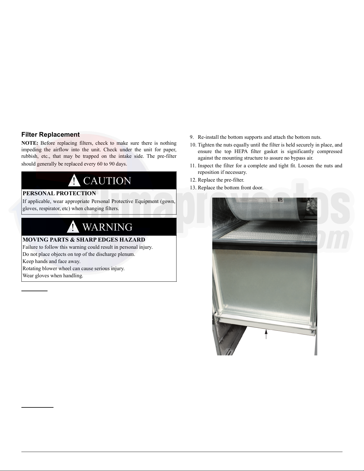
9. Re-install the bottom supports and attach the bottom nuts.
10. Tighten the nuts equally until the filter is held securely in place, and
ensure the top HEPA filter gasket is significantly compressed
against the mounting structure to assure no bypass air.
11. Inspect the filter for a complete and tight fit. Loosen the nuts and
reposition if necessary.
12. Replace the pre-filter.
13. Replace the bottom front door.
A200224
Fig. 6 – Filters
Troubleshooting
Before you request dealer service, check for these easily solved
problems:
• Check your main electrical panel circuit breakers or fuses if the unit
will not turn on.
• Make sure the unit is plugged in to a working 115V electrical outlet.
• Check for sufficient airflow. Filters should be clean and unobstructed.
If you need to contact your authorized dealer for troubleshooting and/or
repairs, be sure to have the model and serial numbers of your equipment
available.
CAUTION
!
PERSONAL PROTECTION
If applicable, wear appropriate Personal Protective Equipment (gown,
gloves, respirator, etc) when changing filters.
WARNING
!
MOVING PARTS & SHARP EDGES HAZARD
Failure to follow this warning could result in personal injury.
Do not place objects on top of the discharge plenum.
Keep hands and face away.
Rotating blower wheel can cause serious injury.
Wear gloves when handling.
HEPA Filter
Pre-lter
©2020 Carrier Edition Date: 04/20 Catalog No: OM-FN1AAF-01
Replaces: New
Operation and Maintenance Manual:
Manufacturer reserves the right to change, at any time, specifications and designs without notice and without obligations.
4
Specifications
A200223
Fig. 7 – Wiring Diagram
Parts
A200226
Fig. 8 – Exploded View
Table 1 – Electrical Specifications
Voltage 115
Hertz 60
Amps 5.0
BRN
BLK - L
YEL - N
GRN/YEL - GND
BLU - 3
FM
TRAN
115V
FILTER
LIGHT
DIFFERENTIAL
PRESSURE
SWITCH
CR
21
2a 1a
NL1
POWER PLUG
LIGHTED
POWER SWITCH
24V
1
2
3
6
5
7
4
8
10
11
12
13
14 15
16
17
9
Table 2 – Parts
Item # Part Number Description Qty
1 346303-401 Discharge Transition Plate 1
2 346284-401 Power Cord 1
3 346294-401 Strain Relief 1
4 HD46AM126 Motor 1
5 346295-402 Gasket, 6” (152 mm) 1
6 346295-401 Gasket, 18” (457 mm) 1
7 346285-701 Caster Assembly 2
8 KH01AZ600 HEPA Filter 1
9 346309-401 Pre-filter, MERV 7 (available locally) 1
10 346279-701 Lower Door Assembly 1
11 346277-701 Upper Door Assembly 1
12 346299-401 Indicator, red 1
13 346300-401 Power Switch, green, lighted 1
14 346297-701 Control Panel Plate 1
15 346301-401 Pitot Tube 1
16 346305-401 Transformer 1
17 HK06WD001 Pressure Switch 1
(not shown) 346304-701 Wiring Harness 1