manuals.online logo
Brands
  1. Home
  2. •
  3. Brands
  4. •
  5. Carrier
  6. •
  7. Heat Pump
  8. •
  9. Carrier 50SZ024 User manual

Carrier 50SZ024 User manual

£n to the Expertg
Installation Instructions
NOTE: Read the entire instruction manual before starting the
installation.
NOTE: Installer: Make sure the Owner's Manual and Service
Instructions are left with the unit after installation.
TABLE OF CONTENTS
Page
SAFETY CONSIDERATIONS ........................ 1
INTRODUCTION .................................. 2
RECEIVING AND INSTALLATION ................ 2-14
Check Equipment ................................. 2
Identify Unit ................................... 2
Inspect Shipment ................................ 2
Provide Unit Support .............................. 2
Roof Curb ..................................... 2
Slab Mount .................................... 2
Ground Mount ................................. 2
Provide Clearances ................................ 2
Field Fabricate Ductwork ........................... 2
Rig and Place Unit ................................ 2
Inspection ..................................... 2
Installation ..................................... 6
Use of Rigging Bracket ........................... 6
Connect Condensate Drain .......................... 7
Select and Install Duc_vork .......................... 7
Configuring Units for Downflow (Vertical) Discharge ..... 8
Install Electrical Connections ........................ 9
High-Voltage Connections ........................ 9
Routing Power Leads Into Unit .................... 10
Connecting Ground Lead to Ground Screw .......... 10
Routing Control Power Wires (24-V) ............... 10
Special Procedures for 208-v Operation ............. 10
PRE-START-UP .................................. 10
START-UP ....................................... 11
Check for Refrigerant Leaks ........................ 11
Start-Up Adjustments ............................. 11
Checking Cooling & Heating Control Operation ....... 11
Checking and Adjusting Refrigerant Charge .......... 11
Indoor Airflow and Airflow Adjustments ............ 14
For 208/230v .................................. 14
MAINTENANCE ............................... 15-20
Air Filter ....................................... 16
Indoor Blower and Motor .......................... 16
Outdoor Coil, Indoor (;oil, and Condensate Drain Pan .... 16
Outdoor Fan .................................... 16
Electrical Controls and Wiring ...................... 21
Refrigerant Circuit ................................ 21
Indoor Airflow .................................. 21
®
Metering Devices-AccuRater Piston ................ 21
TROUBLESHOOTING ............................. 22
START-UP CHECKLIST ........................... 24
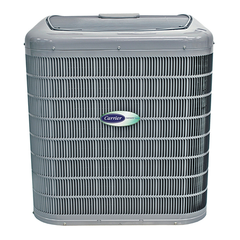
Fig. 1 - Unit 50SZ
C99001
SAFETY CONSIDERATIONS
Installation and servicing of this equipment can be hazardous due to
mechanical and electrical components. Only trained and qualified
personnel should install, repair, or service this equipment.
Untrained personnel can perform basic maintenance functions such
as cleaning and replacing air filters. All other operations must be
performed by trained service personnel. When working on this
equipment, observe precautions in the literature, on tags, and on
labels attached to or shipped with the unit and other safety
precautions that may apply.
Follow all safety codes. Installation must be in compliance with
local and national building codes. Wear safety glasses, protective
clothing, and work gloves. Have fire extinguisher available. Read
these instructions thoroughly and follow all warnings or cautions
included in literature and attached to the unit.
Recognize safety information. This is the safety-alert symbol _.
When you see this symbol on the unit and in instructions or manuals,
be alert to the potential for personal injury. Understand these signal
words: DANGER, WARNING. and CAUTION. These words are
used with the safety-alert symbol. DANGER identifies the most se-
rious hazards which will result in severe personal injury or death.
WARNING signifies hazards which could result in personal injury
or death. CAUTION is used to identify unsafe practices which may
result in minor personal injury or product and property damage.
NOTE is used to highlight suggestions which will result in en-
hanced installation, reliability, or operation.
il
ELECTRICAL SHOCK HAZARD
Failure to follow this warning could result in personal injury
or death.
Before installing or servicing system, always turn off main
power to system. There may be more than one disconnect
switch. Turn off accessory heater power switch if applicable.
INTRODUCTION
The 50SZ packaged heat pump is fully self-contained and designed
for outdoor installation (see Fig. 1). See Fig. 2 and 3 for unit
dinmnsions. All unit sizes have discharge openings for both
horizontal and downflow configurations and are factory shipped
with all downflow duct openings covered. The unit may be installed
either on a rooftop, gound-level cement slab, or directly on the
gound, if local codes permit. (See Fig. 4 for roof curb dimensions.)
RECEIVING AND INSTALLATION
Step 1--Check Equipment
IDENTIFY UNIT
The unit model number and serial number are printed on the unit
informative plate. Check this information against shipping papers.
INSPECT SHIPMENT
Inspect for shipping damage while unit is still on shipping pallet. If
unit appears to be damaged or is torn loose from its anchorage, have
it examined by transportation inspectors before removal. Forward
claim papers directly to transportation company. Manufacturer is
not responsible for any damage incurred in transit. Check all items
against shipping list. Immediately notify the nearest Carrier Air
Conditioning office if any item is missing. To prevent loss or
damage, leave all parts in original packages until installation.
Step 2--Provide Unit Support
For hurricane tie downs, contact distributor for details and PE
Certificate (Professional Engineering), if required.
ROOF CURB
Install accesso Uroof curb in accordance with instmctions shipped
with curb (see Fig. 4). Install insulation, cant strips, roofing, and
flashing. Ductwork must be attached to curb.
IMPORTANT: The gasketing of the unit to the roof curb is critical
for a water tight seal. Install gasketing material supplied with the
roof curb. Improperly applied gasketing also can result in air leaks
and poor unit performance.
Curb should be level to within 1/4 in. (see Fig. 6). This is necessary
for unit drain to function properly. Refer to accessory roof curb
installation instructions for additional information as required.
SLAB MOUNT
Place the unit on a solid, level concrete pad that is a minimum of 4
in. thick, with 2 in. above grade. The slab should extend
approximately 2 in. beyond the casing on all 4 sides of the unit (see
Fig. 7). Do not secure the unit to the slab except when required by
local codes.
GROUND MOUNT
The unit may be installed either on a slab or placed directly on the
ground if local codes permit. Place the unit on level ground prepared
with gravel for condensate discharge.
Step 3--Provide Clearances
Tire required minimum service clearances are shown in Fig. 2 and
3. Adequate ventilation and outdoor air must be provided. The
outdoor fan draws air through the outdoor coil and discharges it
through the top fan grille. Be sure that the fan discharge does not
recirculate to the outdoor coil. Do not locate the unit in either a
corner or under an overhead obstruction. The minimum clearance
under a partial overhang (such as a normal house overhang) is 48 in.
above the unit top. The maximum horizontal extension of a partial
overhang must not exceed 48 in.
IMPORTANT: Do not restrict outdoor airflow. An air restriction at
either the outdoor-air inlet or the fan discharge may be detrimental
to compressor life.
Do not place the unit where water, ice. or snow from an overhang
or roof will damage or flood the unit. Do not install the unit on
carpeting or other combustible materials. Slab-mounted units
should be at least 4 in. above the highest expected water and runoff
levels. Do not use unit if it has been under water.
Step 4_Field Fabricate Ductwork
Secure all ducts to roof curb and building structure on vertical
discharge units. Do not connect ductwork to unit. For horizontal
applications, unit is provided with flanges on the horizontal
openings. All ductwork should be secured to the flanges. Insulate
and weatherproof all external ductwork, joints, and roof openings
with counter flashing and mastic in accordance with applicable
codes.
Ducts passing through an unconditioned space nmst be insulated
and covered with a vapor barrier. If a plenum return is used on a
vertical unit, the return should be ducted through the roof deck to
comply with applicable fire codes. A minimum clearance is not
required around ductwork. Cabinet return- air static shall not exceed
-.25 in. wg.
Step 5--Rig and Place Unit
Rigging and handling of this equipment can be hazardous for many
reasons due to the installation location (roofs. elevated structures,
etc.).
Only trained, qualified crane operators and ground support staff
should handle and install this equipment.
When working with this equipment, observe precautions in the
literature, on tags, stickers, and labels attached to the equipment, and
any other safety precautions that might apply.
Training for operators of the lifting equipment should include, but
not be limited to, the following:
1. Application of the lifter to the load, and adjustment of the
lifts to adapt to various sizes or kinds of loads.
2. Instruction in any special operation or precaution.
3. Condition of the load as it relates to operation of the lifting
kit, such as balance, temperature, etc.
Follow all applicable safety codes. Wear safety shoes and work
gloves.
INSPECTION
Prior to initial use, and at monthly intervals, all rigging brackets and
straps should be visually inspected for any damage, evidence of
wear, structural deformation, or cracks. Particular attention should
be paid to excessive wear at hoist hooking points and load support
areas. Brackets or straps showing any kind of wear in these areas
must not be used and should be discarded.
ELECTRICAL SHOCK HAZARD
Failure to follow this warning could result in personal injury
or death.
Before installing or servicing system, always turn off main
power to system. There may be more than one disconnect
switch. Turn off accessory heater power switch if applicable.
Tag disconnect switch with a suitable warning label.
D,M_NSIONS IN [] ARE IN INCHES
860
[3 39)
/O 6
[278]
i
T
456_4 _
116,551
CONDeNSeR
................................/98 _ .............................
[3144]
ENTRY
FI[LD ROR15_S[RVICE \
A
5703
122 45]
5461
t TOPVIEW
i4020
I:S83)
............
!Ill
:453]
88 3
[3 48]
SUPRL¥
DUCT
5505
(9 83] [21 6/] [9 831
REAR VIEW
" TiTtIITiIi]'IITHXi]
!JHli!!!!!ililll[l
_326 5
[I 68] /1285]
8310
[3272] _DRAIN OUTLET
LEFT SIDE VIEW 19oEo7slNRf
X 220 [087] 5P
............................................. 5_ ' '
Z
I l l
[48 28]
FRONTVIEW
REQUIRED CLEARANCE TO COMBUSTIBLE MATL
(Refer to Maximum Operatin g Clearances) INCHES [rnm]
TOP OF UNIT ................................................................................... 14.00 [355.6]
DUCT SIDE OF UNIT ......................................................................... 2.00 50.8
S DE OPPOS TE DUCTS ................................................................ 14,00 355,6
BOTTOM OF UNIT ............................................................................. 0,50 [12.7]
NEC. REQUIRED CLEARANCES. INCHES mini
BETWEEN UN TS, POWER ENTRY S DE .................................... 42,00 1066.8]
UNIT AND UNGROUNDED SURFACES, POWER ENTRY SIDE ,36,00 [914,0]
UNIT AND BLOCK OR CONCRETE WALLS AND OTHER
GROUNDED SURFACES, POWER ENTRY SIDE ......................... 42.00 [1066.8]
445 [I 75] 5AKO
ROWERENIRY
222 [058}DIA HOLE
CONTROl ENTR_
FllTrlTFITtl
[4 81] RIGHTSIDEVIEW
_ gO
1520]
UNIT
50SZ024
50SZ030
ELECTRICAL
CHARACTERISTICS UNIT WEIGHT
Ib kg
REQUIRED CLEARANCE FOR OPERATION AND SERVICING INCHES [turn]
EVAR COIL ACCESS SIDE ............................................................ 36,00 [914.0]
POWER ENTRY SIDE .................................................................... 42,00 [1066.8]
EXCEPT FOR NEC REQUIREMENTS)
UN TTOP ....................................................................................... 46,00 [1219.2]
SIDE OPPOSITE DUCTS .............................................................. 36,00 [914.0]
DUCT PANEL ................................................................................. 12,00 [304.8] *
*MINIMUM DISTANCES: IF UNIT IS PLACED LESS THAN 304.8 [12.00] FROM
WALL SYSTEM, THEN SYSTEM PERFORMANCE MAYBE COMPROMISE.
UNIT HEIGHT
IN. [MM]
"A"
A05162
Z
17.6 [447]
13.0 [330]
CENTER OF GRAVITY
IN. [MM]
X Y
208/230-1-60 343 156 39.02 [991 ] 20.0 [508] 19.3 [490]
208/230-1-60, 208/230-3-60 366 166 41.02 [1042] 20.0 [508] 14.0 [356]
il
Fig. 2 -50SZ024-030 Unit Dimensions
i27!]
[DO0
J
}4 ...........................
COMPRESSOR,B OWER,E C] R C NEAT\
& ELECTRIC ACCESS \ \\
(42 94]
FIELD E_TRY
i¸
123 .................... '\\
[44 22] \\\ DRA 0 lET
90 [0 /5 ffP
LEFT SIDE VIEW __o _o8.oP
t TOP VIEW
[47085
t
_226 3
[4828]
FRONT VIEW
T
4020
/15 831
{463]
88 3
[3 481
222 [088]
CONTROl ENTRY
50
[0 20]
RIGHT SIDE VIEW
REQUIRED CLEARANCE TO COMBUSTIBLE MATL
(Refer to Maximum Operating Clearances) INCHES [mm]
TOP OF UNIT ................................................................................... 14.00 [355.6]
DUCT SIDE OF UNIT ......................................................................... 2.00 [50.8]
SIDE OPPOSITE DUCTS ................................................................ 14.00 [355.6]
BOTTOM OF UNIT ............................................................................. 0.50 [12.7]
NEC. REQUIRED CLEARANCES. INCHES [mm]
BETWEEN UNITS, POWER ENTRY SIDE .................................... 42.00 [1066.8]
UNIT AND UNGROUNDED SURFACES, POWER ENTRY SIDE .36.00 [914.0]
UNIT AND BLOCK OR CONCRETE WALLS AND OTHER
GROUNDED SURFACES, POWER ENTRY SIDE ......................... 42.00 [1066.8]
REQUIRED CLEARANCE FOR OPERATION AN D SERVICING INCHES [mm]
EVAR COIL ACCESS SIDE ............................................................ 36.00 [914.0]
POWER ENTRY SIDE .................................................................... 42.00 [1066.8]
(EXCEPT FOR NEC REQUIREMENTS)
UNIT TOP ....................................................................................... 48.00 [1219.2]
SIDE OPPOSITE DUCTS .............................................................. 36.00 [914.0]
DUCT PANEL ................................................................................. 12.00 [304.8] *
*MINIMUM DISTANCES: IF UNIT IS PLACED LESS THAN 304.8 [12.00] FROM
WALL SYSTEM, THEN SYSTEM PERFORMANCE MAYBE COMPROMISE.
UNIT
50SZ036
50SZ042
50SZ048
50SZ060
ELECTRICAL
CHARACTERISTICS
208/230-1-60, 208/230-3-60, 460-3-60
208/230-1-60, 208/230-3-60, 460-3-60
208/230-1-60, 208/230-3-60, 460-3-60
208/230-1-60, 208/230-3-60, 460-3-60
UNIT WEIGHT
Ib kg
433 196
480 209
480 218
492 223
UNIT HEIGHT
IN.[MM]
"A"
42.98 [1092]
46.98 [1193]
46.98 [1193]
46.98 [1193]
A05126
CENTER OF GRAVITY
IN. [MM]
XYZ
21.0 [533] 20.5 [520] 16.6 [422]
21.0 [533] 20.5 [520] 17.1 [434]
21.0 [533] 20.0 [508] 17.4 [442]
21.0 [533] 20.0 [508] 17.6 [447]
Fig. 3-50SZ036-060 Unit Dimensions
base_ [[[ .......
/Screw _ @
/(NOTE A) _§
/
/slur, :';allg_ "_ _ WOOdnailer*_Fla
Iu0p, ____.__41K ilFdbRooz urb.
[ It:i:::tl _J¢Insulation(field
Roofing m_, II supphed)
/ field supplied II.
\IIvs!:!tl II_ Ductwork
\ __Jtl H field supplied]
Roof Curb for Small Cabinet
Note A: When unit mounting screw is used,
retainer bracket must also be used.
Roof Curb for Large Cabinet
Note A: When unit mounting screw is used,
retainer bracket must also be used.
Retlm opening
(BXC)
deck paq
Sho_
Suppod
Long
Suppod
E D
R/A
Insulated
deck pan
_Gasket around_
duct
Gasket around
outer edge \
'N\\
\/
S/A
/\
UNIT SIZE
50SZ024-030
50SZ036-060
NOTES:
ODS CATALOG A B
NUMBER IN. (aM) IN. (aM)
CPRFCURB006A00 8 (203) 11 (279)
CPRFCURB007A00 14 (356) 11 (279)
CPRFCURB008A00 8 (203) 16-3/16 (411)
CPRFCURB009A00 14 (356) 16-3/16 (411)
1. Roof curb must be set lip for unit being installed.
C
IN. (MM)
16-1/2 (419)
16-1/2 (419)
17-3/8 (441)
17-3/8 (441)
D
IN. (MM)
28-3/4 (730)
28-3/4 (730)
40-1/4 (1022)
40-1/4 (1022)
E
IN. (MM)
30-3/8 (771)
30-3/8 (771)
41-15/16 (1065)
41-15/16 (1065)
F
IN. (MM)
44-5/16 (1126)
44-5/16 (1126)
44-7/16 (1129)
44-7/16 (1129)
A05308
G
IN.(MM)
45-15/16 (1167)
45-15/16 (1167)
46 - 1/16 (1169)
46-1/16 (1169)
2. Seal strip nlust be applied, as required, to unit being installed.
3. Dimensions are in inches.
4. Dimension in ( ) are in millimeters.
5. Roof curb is made of 16 gauge steel.
6. Attach ductwork to curb (flmlges of duct rest on curb).
7. Insulated pmlels: I in. thick fiberglass 1 lb. density.
8. When unit mounting screw is used (see Note A), a retainer bracket must be used as well. This bracket must also be used when required by code for hurricane or seismic
conditions. This bracket is available throt_gh Mierometl.
Fig. 4 - Roof Curb Dimensions
12
/
Y
Z
DETAI L A
C) X3
C00071
SEEDETAIL
CORNER WEIGHTS (SMALL CABINET)
Unit
Total Weight
Corner Weight 1
Corner Weight 2
Corner Weight 3
Corner Weight 4
Rigging Weight
CORNER WEIGHTS (LARGE CABINET)
MINIMUMHEIGHT: 36'
UNITHEIGHT
024 030 Unit 036 042 048 060
343 366 Total Weight 433 460 480 492
69 74 Corner Weight 1 87 93 97 99
53 57 Corner Weight 2 68 72 74 76
83 88 Corner Weight 3 104 111 116 119
138 147 Corner Weight 4 174 184 193 198
353 376 Rigging Weight 443 470 490 502
Fig. 5 -50SZ Unit Corner Weights (in Pounds) and Suggested Rigging
A05161
MAXIMUMALLOWABLE
DIFFERENCE (in.)
B A-B B-C A-C
1/4 1/4 1/4
C99065
Fig. 6 - Unit Leveling Tolerances
I
I
I
I
I
I
I
I
II
I
I
I
2"
L
I EVAR COIL COND. COIL
Fig. 7- Slab Mounting Detail
C99096
UNIT FALLING HAZARD
Failure to follow this warning could result in personal injury
or death.
Never stand beneath rigged units or lift over people.
INSTALLATION
The lifting/rigging bracket is engineered and designed to be
installed on!y on Small Packaged Products. This bracket is to be
used to rig/lift a Small Packaged Product onto roefs or other
elevated structures.
PROPERTY DAMAGE HAZARD
Failure to fellow this warning could result in personal
injury/death or property damage.
Rigging brackets for one unit use only. When removing a
unit at the end of its useful life, use a new set of brackets.
USE OF RIGGING BRACKET
Field Installation of Rigging Bracket
1. If applicable, remove unit from shipping carton. Leave top
shipping skid on the unit for use as a spreader bar to prevent
the rigging straps from damaging the unit. If the skid is not
available, use a spreader bar of sufficient length to protect the
unit from damage.
2. Remove 4 screws in unit corner posts.
3.Attacheachofthe4metalriggingbracketsunderthepanel
rainlip(seeFig.5).Usethescrewsremovedinstep2above
tosecurethebracketstotheunit.
PROPERTYDAMAGEHAZARD
Failuretofollowthiswarningcouldresultin personal
injury/deathorpropertydamage.
RiggingbracketMUSTbeundertherainliptoprovkle
adequatelifting.
PROPERTYDAMAGEHAZARD
Failuretofollowthiswarningcouldresultin personal
injury/deathorpropertydamage.
Donotstripscrewswhenre-securingtheunit.Ifascrewis
stripped, replace the stripped one with a larger diameter screw.
Ri_in_/Liftin_ of Unit
1. Bend top of brackets down approximately 30 degrees from
the corner posts.
2. Attach straps of equal length to the rigging brackets at
opposite ends of the unit. Be sure straps are rated to hold the
weight of the unit (see Fig. 5).
3. Attach a clevis of sufficient strength in the middle of the
straps. Adjust the clevis location to ensure unit is lifted level
with the ground.
4. After unit is securely in place, detach rigging straps. Remove
corner posts, screws, and rigging brackets, then reinstall
screws.
UNIT FALLING HAZARD
Failure to follow this warning could result in personal
injury/death or property damage.
When straps are taut. the clevis should be a minimum of 36
inches above the unit top cover.
After the unit is placed on the roof curb or mounting pad, remove
the top crating. On 50SZ060 units only, 2 wire ties fastened to the
outdoor coils and reversing valve/accumulator assembly must be
cut. Remove the left and front Iouvered panels and corner post to
access wire ties. The wire tie to be cut on the left is located
approximately 4 in. down the tube sheet. The wire tie to be cut on
the right is located approximately 6 in. down the tube sheet.
Step 6--Connect Condensate Drain
NOTE: When installing condensate drain connection be sure to
comply with local codes and restrictions.
Model 50SZ disposes of condensate water through a 3/4 in. NPT
fitting which exits through the base on the evaporator coil access
side. See Fig. 2 & 3 for location.
Condensate water can be drained directly onto the roof in rooftop
installations (where permitted) or onto a gravel apron in ground
level installations. Install a field-supplied condensate trap at end of
condensate connection to ensure proper drainage. Make sure that
the outlet of the trap is at least 1 in. lower than the drain pan
condensate connection to prevent the pan from overflowing (see
Fig. 8). When using a gravel apron, make sure it slopes away from
the unit.
Connect a drain tube using a minimum of 3/4 in. PVC or 3/4 in.
copper pipe (all field-supplied) at the outlet end of the 2-in. trap. Do
not undersize the tube. Pitch the drain tube downward at a slope of
at least l-in. for every 10 ft. of horizontal run. Be sure to check the
drain tube for leaks. Prime trap at the beginning of the cooling
season start-up.
1" (25mm) MIN.
TRAP
_-_ OUTLET
2" (50mm) MIN.
099013
Fig. 8-Condensate Trap
Step 7--Select and Install Ductwork
The design and installation of the duct system must be in accordance
with the standards of the NFPA for installation of non-residence
type air conditioning and ventilating systems. NFPA 90A or
residence type, NFPA 90B and/or local codes and ordinances.
Select and size ductwork, supply- air registers, and return air grilles
according to ASHRAE (American Society of Heating,
Refrigeration, and Air Conditioning Engineers) reconmmndations.
The unit has duct flanges on the supply- and return-air openings on
the side of the unit.
When designing and installing ductwork, consider the following:
1. All units should have field- supplied filters or accessory filter
rack installed in the return-air side of the unit.
Recommended sizes for filters are shown in Table 1.
2. Avoid abrupt duct size increases and reductions. Abrupt
change in duct size adversely affects air performance.
IMPORTANT: Use flexible connectors between ductwork and
unit to prevent transmission of vibration. Use suitable gaskets to
ensure weather tight and airtight seal. When electric heat is installed,
use fireproof canvas (or similar heat resistant material) connector
between ductwork and unit discharge connection. If flexible duct is
used, insert a sheet metal sleeve inside duct. Heat resistant duct
connector (or sheet metal sleeve) must extend 24-in. from electric
heater element.
3. Size ductwork for cooling air quantity (cfm). The minimum
air quantity for proper electric heater operation is listed in
Table 2. Heater limit switches may trip at air quantities below
those recommended.
4. Seal. insulate, and weatherproof all external ductwork. Seal.
insulate and cover with a vapor barrier all duc_vork passing
through conditioned spaces. Follow latest Sheet Metal and
Air Conditioning Contractors National Association
(SMACNA) and Air Conditioning Contractors Association
(ACCA) minimum installation standards for residential
heating and air conditioning systems.
5. Secure all ducts to building structure. Flash, weatherproof,
and vibration-isolate duct openings in wall or roof
according to good construction practices.
Table1--Physical Data-Unit 50SZ
JNIT SIZE
_IOMINAL CAPACITY (ton)
3PERATING WEIGHT (lb.)
3OMPRESSOR
REFRIGERANT (R-22) Quantity (lb.)
REFRIGERANT METERING DEVICE
3RIFICE OD (in,)
3UTDOOR COIL
Rows... Fins/in.
Face Area (sq. ft.)
3UTDOOR FAN
Nominal Cfm
Diameter
Motor HP (RPM)
NDOOR COIL
Rows... Fins/in.
Face Area (sq. ft.)
INDOOR BLOWER
Nominal Airflow (Cfm)
Size (in.)
Motor HP (RPM)
RETURN-AIR FILTERS (IN,)*
Throwaway
024 048 060
2 4 5
289 418 430
7.8 t2,3 12.0
0.065 0.088 0.101
2...21 2...21 2.-21
11.9 19.4 19.4
2700 3300 3300
22 22 22
1/8 (825) 1/4 (1100) 1/4 (1100)
3...17 3...17 4_.17
3.7 5.6 5.6
800 1600 1750
I0x10 11x10 11x10
1/3 (1050) I/2 (1075) 1.0 (1040)
20x24x t 20x24x 1 24x36x 1 24x36x 1 24x36x 1 24x36x 1
030
2-1/2
312
8.4
0.070
2...21
13.6
2700
22
1/8 (825)
3...17
3.7
t000
10x10
i/3 (1o5o)
036 042
3 3-1/2
311 398
Scroll
10.9 t0.9
AccuRater '_
0.080 0.088
2-.21 2...21
15.5 19.4
2800 2800
22 22
1/8 (825) 1/8 (825)
3...17 3.-17
4.7 4.7
1200 1400
11x10 11x10
I/2 (1000) I/2 (1075)
*Required filter sizes shown are based on the larger of the ARI (Air Conditioning and Refrigeration Institute) rated cooling airflow or the heating airflow velocity
of 300 if/minute for throwaway type. For permanent fitters, follow filter manufacturer's recommendations for filter size based on allowable face velocity. Air filter
pressure drop for non-standard filters must not exceed 0.06 in. wg.
Table 2--Mininmm Airflow for Safe Electric Heater Operation (Cfm)
SiZE 024 030 036 042 048 060
Cfm 800 1000 1200 1400 1600 1750
CONFIGURING UNITS FOR DOWNFLOW (VERTICAL)
DISCHARGE
ELECTRICAL SHOCK HAZARD
Failure to follow this warning could result in personal injury
or death.
Before performing service or maintenance operations on the
system, turn off main power to unit and install lockout tag.
1. Open all electrical disconnects and install lockout tag before
starting any service work.
2. Removereturnductcoverlocatedon ductpanelbybreaking
four (4) connecting tabs with screwdriver and a hammer (see
Fig. 9 & 10).
3. To remove supply duct cover, break front and right side
connecting tabs with a screwdriver and a hammer. Push
louver down to break rear and left side tabs (see Fig. 9 & 10).
4. If unit ductwork is to be attached to vertical opening flanges
on the unit composite base (jackstand applications only), do
so at this time. Collect ALL screws that were removed. Do
not leave screws on rooftop, as permanent damage to the roof
may occur.
5. It is recommended that the unit base insulation around the
perimeter of the vertical return-air opening be secured to the
unit base with aluminum tape. Applicable local codes may
require aluminum tape to prevent exposed fiberglass.
6. Cover both horizontal duct openings with the duct cnvers
from the accessory duct cover kit. Ensure opening is air-and
watertight.
7. After completing unit conversion, perfornr all safety checks
and power up unit.
NOTE:The design and installation of the duct system must be in
accordance with the standards of the NFPA for installation of
nonresidence-type air conditioning and ventilating systems, NFPA
90A or residence-type, NFPA 90B: and/or local codes and
ordinances.
Adhere to the following criteria when selecting, sizing, and
installing the duct system:
1. Units are shipped for side shot installation.
2. Select and size ductwork, supply-air registers, and
return-air grilles according to American Society of Heating,
Refrigeration and Air Conditioning Engineers (ASHRAE)
recommendations.
3. Use flexible transition between rigid ductwork and unit to
prevent transmission of vibration. The transition may be
screwed or bolted to duct flanges. Use suitable gaskets to
ensure weathertight and airtight seal.
4. All units must have field-supplied filters or accessory filter
rack installed in the return-air side of the unit.
Recommended sizes for filters are shown in Table 1.
5. Size all ductwork fnr maxinmm required airflow (either
heating or cooling) for unit being installed. Avoid abrupt
duct size increases or decreases or performance may be
affected.
6. Adequately insulate and weatherproof all ductwork located
outdoors. Insulate ducts passing through unconditioned
space, and use vapor barrier in accordance with latest issue
of SMACNA and ACCA minimum installation standards
for heating and air conditioning systems. Secure all ducts to
building structure.
7. Flash. weatherproof, and vibration-isolate all openings in
building structure in accordance with local cndes and good
building practices.
// i
SUPPLY
DUCT
OPENING
,
RETURN
DUCT
OPENING
Fig. 9 - Supply and Return Duct Opening
C99011
DUCT COVERS REMOVED
Fig. 10 -Vertical Duct (.'over Removed
Step 8--Instan Electrical Connections
C99012
ELECTRICAL SHOCK HAZARD
Failure to follow this warning could result in personal injury
or death.
The unit cabinet must have an uninterrupted, unbroken
electrical ground to minimize the possibility of personal injury
if an electrical fault should occur. This ground may consist of
an electrical wire connected to the unit ground screw in the
control compartment, or conduit approved for electrical
ground when installed in accordance with NEE;, ANSI/NFPA
American National Standards Institute/National Fire
Protection Association (latest edition) (in Canada, Canadian
Electrical Code CSA C22.1) and local electrical codes.
[;NIT COMPONENT DAMAGE HAZARD
Failure to follow this caution may result in damage to the unit
being installed.
1. Make all electrical connections in accordance with NEC
ANSI/NFPA (latest edition) and local electrical codes
governing such wiring. In Canada. all electrical
connections must be in accordance with CSA standard
C22.1 Canadian Electrical Code Part i and applicable local
codes. Refer to unit wiring diagram.
2. Use only copper conductor for connections between
field-supplied electrical disconnect switch and unit. DO
NOT USE ALUMINUM WIRE.
3. Be sure that high-voltage power to unit is within operating
voltage range indicated on unit rating plate. On 3-phase
units, ensure phases are balanced within 2 percent. Consult
local power company for correction of improper voltage
and/or phase imbalance.
4. Do not damage internal components when drilling through
any panel to mount electrical hardware, conduit, etc.
HIGH-VOLTAGE CONNECTIONS
The unit must have a separate electrical service with a
field-supplied, waterproof disconnect switch mounted at, or within
sight from the unit. Refer to the unit rating plate. NEE; and local
codes for maximum fuse/circuit breaker size and minimum circuit
amps (ampacity) for wire sizing (see Table 3 for electrical data).
The field-supplied disconnect may be mounted on the unit over the
high-voltage inlet hole when the standard power and low-voltage
entry points are used. See Fig. 2 and 3 for acceptable location.
If the unit has an electric heater, a second disconnect may be
required. Consult the Installation, Start-Up, and Service
Instructions provided with the accessory for electrical service
connections.
Operation of unit on improper line voltage constitutes abuse and
may cause unit damage that could affect warranty.
Proceed as follows to complete the high-voltage connections to the
unit.
Single phase units:
1. Run the high-voltage (L1, L2) and ground lead into the
control box.
2. Connect ground lead to chassis ground connection.
3. Locate the black and yellow wires connected to the line side
of the contactor.
4. Connect field L1 to black wire on connection 11 of the
compressor contactoD
5. Connect field wire L2 to yellow wire on connection 23 of the
compressor contactor.
Three-phase units:
1. Run the high-voltage (L1, L2, L3) and ground lead into the
control box.
2. Connect ground lead to chassis ground connection.
3. Locate the black and yellow wires connected to the line side
of the contactor.
4. Connect field L1 to black wire on connection 11 of the
compressor contactor.
5. Connect field wire L2 to yellow wire on connection 13 ofthe
compressor contactoD
d. Connect field wire L3 to blue wire from compressor.
ROUTING POWER LEADS INTO UNIT
Use only copper wire between disconnect and unit. The
high-voltage leads should be in a conduit until they enter the duct
panel: conduit termination atthe duct panel must be watertight. Run
the high-voltage leads through the power entry knockout on the
power entry side panel. See Fig. 2 and 3 for location and size. When
the leads are inside the unit, run leads up the high-voltage raceway
to the line wiring splice box (see Fig. 12). For single-phase units,
connect leads to the black and yellow wires (see Fig. 12). On all
3-phase units, connect the leads to the black, yellow and blue ,,vires.
CONNECTING GROUND LEAD TO GROUND SCREW
Connect the ground lead to the chassis using the ground screw in the
wiring splice box (see Fig. 11).
ROUTING CONTROL POWER WIRES (24-V)
Form a drip-loop with the thermostat leads before routing them into
the unit. Route the thermostat leads through grommeted.
low-voltage hole provided in unit into unit control power splice box
(see Fig. 2 and 3). Connect thermostat leads to unit control power
leads as shown in Fig. 11.
The unit transformer supplies 24-v power for complete system
including accessory electrical heater. An automatic-reset circuit
breaker is provided in the 24-v circuit; see the caution label on the
transformer. Transformer is factory wired for 230-v operation. If
supply voltage is 208-v. rewire transformer primary as described in
Special Procedures for 208-v Operation section.
SPECIAL PROCEDURES FOR 208v OPERATION
1. Disconnect the yellow primary lead from the transformer.
See unit wiring label (see Fig. 11).
2. Connect the yellow primary lead to the transformer terminal
labeled 200-v.
Indoor blower-motor speeds may need to be changed for 208-v
operation. Refer to indoor airflow and airflow adjustments section.
©
@
@
@
®
THERMOSTAT
AND SUBBASE
[
l
_BRN--
_ORN--
_RED--
_GRN_
UNIT CONTROL POWER
SPLICE BOX
C99056
Fig. 11 - Control Connections
GROUND SCREW
(IN SPLICE BOX)
SINGLE-PHASE
CONNECTIONS
TO DISCONNECT
PER NEC
GROUND
LEAD
L1 _BLK--
L2 ........ /Q---- YEL--
3-PHASE L3 _BLU--
CONNECTIONS NOTE: Use copper wire only.
LEGEND
NEC - National Electrical Code
Field Wiring
Splice Connections
099057
Fig. 12 -Line Power Connections
24V Circuit Breaker
24 Volt CornI
Fig. 13 - Control Wiring Plate
PRE- START - UP
C99070
FIRE, EXPLOSION, ELECTRICAL SHOCK HAZARD
Failure to follow this warning could result in personal injury
or death and/or property damage.
1. Follow recognized safety practices and wear protective
goggles when checking or servicing refrigerant system.
2. Relieve and recover all refrigerant from system before
touching or disturbing anything inside terminal box if
refrigerant leak is suspected around compressor terminals.
3. Never attempt to repair soldered connection while
refrigerant system is under pressure.
4. Do not use torch to remove any component. System
contains oil and refrigerant under pressure.
5. To remove a component, wear protective goggles and
proceed as follows:
a. Shut off electrical power to unit and install lockout
tag.
b. Relieve and reclaim all refrigerant from system
using both high- and low-pressure ports.
c. Cut component connecting tubing with tubing
cutter and remove component from unit.
d. Carefully unsweat remaining tubing stubs when
necessary. Oil can ignite when exposed to flame.
Proceed as follows to inspect and prepare the unit for initial start-up:
1. Remove all access panels.
i0
2.ReadandfollowinstructionsonallDANGER,WARNING,
CAUTION.andINFORMATIONlabelsattachedto,or
shippedwith.unit.
3.Makethefollowinginspections:
a.Inspectforshippingandhandlingdamages,suchas
brokenlines,looseparts,disconnected,,vires.etc.
b.Inspectforoilatallrefrigeranttubingconnectionsandon
unitbase.Detectingoilgenerallyindicatesarefrigerant
leak.Leaktestallrefrigeranttubingconnectionsusing
electronicleakdetector,orliquid-soapsolution.If a
refrigerantleakisdetected,seeCheckforRefrigerant
Leakssection.
c.Inspectallfield-andfactory-wiringconnections.Be
surethatconnectionsarecompletedandtight.
d.Ensure,,viresdonottouchrefrigeranttubingorsharp
sheetmetaledges.
e.Inspectcoilfins.If damagedduringshippingand
handling,carefullystraightenfinswithafincomb.
4.Verifythefollowingconditions:
a.Makesurethatoutdoorfanbladeiscorrectlypositioned
infanorifice(seeFig.14).
b.Makesurethatcondensatedrainpanandtraparefilled
withwatertoensureproperdrainage.
c.Makesurethatalltoolsandmiscellaneouslooseparts
havebeenremoved.
5.Compressorsareinternallyspringmounted.Donotloosen
orremovecompressorholddownbolts.
6.Eachunitsystemhastwo(2)Schrader-typeports,one
low-sideSchraderfittinglocatedonthesuctionline,andone
high-sideScbraderfittinglocatedonthecompressor
dischargeline.Besurethatcapsontheportsaretight.
7.Highflowvalvesarelocatedonthecompressorhotgasand
suctiontubes.Thesevalvescannotbeaccessedforservice
inthefield.Ensuretheplasticcapsareinplaceandtightor
thepossibilityofrefrigerantleakagecouldoccur.
MOTOR _ GRILLE
1/8" MAX BETWEEN H_I
MOTOR AND FAN HUB MOTOR SHAFT
Fig. 14 - Fan Blade Clearance
cggoo9
START-UP
CHECK FOR REFRIGERANT LEAKS
Proceed as follows to locate and repair a refrigerant leak and to
charge the unit:
1. Locate leak and make sure that refrigerant system pressure
has been relieved and reclaimed from both high- and
low-pressure ports.
2. Repair leak following accepted practices.
NOTE: Install a filter drier whenever the system has been opened
for repair.
3. Add a small charge of R-22 refrigerant vapor to system and
leak-test unit.
4. Recover refrigerant from refrigerant system and evacuate to
500 microns if no additional leaks are found.
5. Charge unit with R-22 refrigerant, using a volumetric
charging cylinder or accurate scale. Refer to unit rating plate
for required charge. Be sure to add extra refrigerant to
compensate for internal volume of filter drier.
START-UP ADJUSTMENTS
Complete the required procedures given in the Pre-Start-Up
section before starting the unit. Do not jumper any safety devices
when operating the unit. Do not operate the unit in cooling mode
when the outdoor temperature is below 40°F (unless accessory
low-ambient kit is installed). Do not rapid cycle the compressor.
Allow 5 min. between "on" cycles to prevent compressor damage.
CHECKING COOLING AND HEATING CONTROL
OPERATION
Start and check the unit for proper cooling control operation as
follows:
1. Place room thermostat SYSTEM switch in OFF position.
Observe that blower motor starts when FAN switch is placed
in ON position and shuts down within 60 sec. when FAN
switch is placed in AUTO position.
2. Place SYSTEM switch in COOL position and FAN switch
in AUTO position. Set control below room temperature.
Observe that cooling cycle shuts down when control setting
is satisfied.
3. Place system switch in HEAT position. Set control above
room temperature. Observe that compressor, outdoor fan.
and indoor blower motor starts. Observe that heating cycle
shuts down when control setting is satisfied.
4. When using an automatic changeover room thermostat,
place both SYSTEM and FAN switches in AUTO positions.
Observe that unit operates in Cooling mode when
temperature control is set to call for Cooling (below room
temperature), and unit operates in Heating mode when
temperature control is set to call for Heating (above room
temperature).
IMPORTANT: Three-phase. scroll compressors are direction
oriented. Unit must be checked to ensure proper compressor
3-phase power lead orientation. If not corrected within 5 minutes.
the internal protector will shut off the compressor. The 3-phase
power leads to the unit must be reversed to correct rotation. When
turning backwards, the difference between compressor suction and
discharge pressures may be dramatically lower than normal.
CHECKING AND ADJUSTING REFRIGERANT CHARGE
The refrigerant system is fully charged with R-22 refrigerant and
is tested and factory sealed. Allow system to operate a minimum of
15 minutes before checking or adjusting charge.
NOTE: Adjustment of the refrigerant charge is not required unless
the unit is suspected of not having the proper R-22 charge. The
charging label and the tables shown refer to system temperatures and
pressures in cooling mode only. A refrigerant charging label is
attached to the outside of the service access door. If charge level is
suspect in Heating mode, reclaim all refrigerant and charge to
nameplate amount. (This information may be obtained from the
physical data table also.)
IMPORTANT: When evaluating the refrigerant charge, an
indicated adjustment to the specified factory charge must always be
very minimal. If a substantial adjustnmnt is indicated, an abnormal
condition exists somewhere in the cooling system, such as
insufficient airflow across either or both coils.
11
Table3--Electrlcal Data--50SZ
ELECTRIC HEAT SINGLE POINT POWER SUPPLY
il
UNIT SIZE
024
O3O
036
042
048
060
V-PH-HZ
208/230-1-60
208/230-1-60
208/230-3-60
208/230-1-60
208/230-3-80
460-3-60
208/230-1-60
208/230-3-60
460-3-60
208/230-1-60
208/230-3-60
460-3-60
208/230-1-80
208/230-3-60
480-3-60
VOLTAGE
RANGE
MIN MAX
187 253
t87 253
187 253
t87 253
187 253
414 506
t87 253
187 253
414 506
t87 253
187 253
414 506
187 253
187 253
414 506
COMPRESSOR OFM IFM
FLA FLA
RLA LRA
10.9 54,0 0.9 2.0
14.0 72.5 0.9 2.0
9.0 63,0 0.9 2.0
16.0 88.0 0.9 3.1
10.2 77.0 0.9 3.1
5.1 39,0 0.6 1.6
18.4 t04.4 0.9 4.1
12.4 88.0 0.9 4.1
5.6 44,0 0.6 1.9
18.3 t09.0 t.5 4.1
12.4 88,0 1.5 4.t
5,4 44.0 0.9 t .9
25.0 148.0 1.5 6.2
17.3 123.0 1.5 8.2
7.7 49.5 0.9 2.7
NOMINAL FLA
kW*
-/- -/-
3.8/5 18.1/20,8
5.4/7.2 28.0/80.0
7.5/10.0 36.1/4t .7
-/- -/-
3.8/5 18.1/20.8
5,4/7,2 28.0/30.0
7.5/10,0 36.1/41,7
11.3/15.0 54.2/82.5
-/- -/-
3.8/5.0 18.1/20,8
7.5/10.0 38.1/41.7
tl .3/15.0 54.2/62.5
-/- -/-
3.8/5 18.1/20.8
7.5/10.0 36.1/41.7
11.3/15.0 54.2/62.5
-/- -/-
3,8/5,0 18.1/20,8
7.5/10,0 36.1/41,7
11.3/15.0 54.2/82.5
-/- -/-
3.8/5.0 10.4/12,0
7.5/10.0 20.8/24.1
tl .3/15.0 31.3/36.t
-/- -/-
3.8/5.0 18.1/20.8
5,4/7,2 28.0/30.0
7.5/10,0 36.1/41,7
11.3/15.0 54.2/82.5
-/- -/-
3.8/5.0 18.1/20,8
7.5/10.0 38.1/41.7
tl .3/15.0 54.2/82.5
15.0/20.0 72.0/83.1
-/- -/-
3.8/5.0 10.4/12,0
7.5/10.0 20.8/24.1
tl .3/15.0 31.3/36.t
-/- -/-
3.8/5.0 18.1/20.8
7.5/10.0 36.1/41.7
11.3/15.0 54.2/62.5
-/- -/-
3,8/5,0 18.1/20,8
7.5/10,0 36.1/41,7
11.3/15.0 54.2/82,5
t5,0/20.0 72.0/83.t
-/- -/-
3.8/5.0 10.4/12.0
7.5/10.0 20.8/24.1
11.3/15.0 31.3/36.1
-/- -/-
3,8/5,0 18.1/20,8
7.5/10,0 36.1/41,7
11.3/15.0 54.2/82.5
-/- -/-
3.8/5.0 18.1/20,8
7.5/10.0 38.1/41.7
tl .3/15.0 54.2/82.5
15.0/20.0 72.0/83.1
-/- -/-
3, 8/5,0 10.4/12,0
7,5/1 O,O 20.8/24.1
11.3/15.0 61.3/36.1
MCA MOCP
t8,5/16.5 20/20
39,1/42.6 45/45
49,0/54.0 50/60
61.7/68.6 70/70
20,4/20,4 25/25
43.0/46.4 50/50
52,9/57.9 60/60
65,5/72,5 70/80
88.1/98.5 90/1 O0
t4,1/14.1 20/20
36,7/40.1 40/45
59.2/86.2 80/70
81.8/92.2 90/1 O0
24,0/24.0 30/30
46.8/50,1 50/60
69.2/76.1 70/80
91.7/102.2 100/110
18.8/16.8 20/20
39.4/42.8 45/45
61,9/68.9 70/70
84.5/94.9 90/1 O0
8.5/8.5 t5/15
21,8/23,6 25/25
34.8/38.6 -/-
47.6/53.7 -/-
28,0/28.0 35/35
50,6/54.0 80/60
60.5/65.5 70/70
73,1/80.1 80/90
95.7/108.1 100/110
20.5/20.5 25/25
43,1/46.5 50/50
85.8/72.6 70/80
88.2/98.6 90/1 O0
110.5/124.4 125/125
9.5/9.5 t5/15
22,5/24.5 25/25
35.5/39.5 -/-
48.6/54.6 -/-
28,5/28.5 35/35
51.0/54.5 60/60
73.8/80.6 80/90
96.2/106.6 100/110
21.1/21.1 25/25
43.7/47.1 50/50
68,2/73.2 70/80
88.8/99.2 90/1 O0
tt1.1/125.0 t25/125
9.5/9.5 15/15
22.5/24.5 25/25
35.5/39.5 -/-
48,6/54.6 -/-
39,0/39.0 50/50
61.5/65.0 80/80
84,1/91.0 100/1 O0
108.6/117.1 110/125
29.3/29.3 35/35
51,9/55.3 60/60
74.4/81.4 80/90
97.0/107.4 100/110
119.3/133.2 125/150
13.2/16.2 20/20
28.2/28.2 30/30
39,2/43.3 -/-
52.3/58.3 -/-
12
LE_ENO CQ US
FLA -- Full Load Amps
LRA -- Locked Rotor Amps
MCA -- Minimum Circuit Arnps
MOCP -- Maximurn Overcurrent Protection
RLA -- Rated Load Arnps
NOTES:
1. In compliance with NEC (National Electrical Code) requirements
for multimotor and combination load equipment (refer to NEC
Articles 430 and 440), the overcurrent protective device for the
unit shall be Power Supply fuse. The CGA (Canadian Gas
Association) units may be fuse or circuit breake_
2. Minimum wire size is based on 60°0 copper wire. If other than
60°0 wire is used, or if length exceeds wire length in table,
deterrnine sizefrom NEC.
3. Unbalanced g-Phase Supply Voltage
Never operate _motor where aphase imbalance in supply volt-
age is greater than 2%. Use the following formula to determine
the percentage of voltage imbalance.
% Voltage imbalance
- 100 x rnax voltage deviation from a_erage voltage
average voltage
. Heater capacity (kW) based on heater voltage of 208v & 240v.
If power distribution voltage to unit varies from rated heater
voltage, heater kW will vary accordingly.
EXAMPLE: Supply voltage is 230-3-60.
AB = 228 v
BC = 231 v
AC = 227 v
Average Voltage = 228 + 231 + 227
3
686
3
- 229
Determine maximum deviation from average voltage.
(AB) 229 - 228 - 1 v
(BC) 231 - 229 - 2 v
(AC) 229 - 227 = 2 v
Maximum deviation is 2 v.
Determine percent of voltage imbalance.
2
% Voltage Imbalance - 100 x --
229
-0.8%
This amount of phase imbalance is satisfactory as it is below the
maximum allowable 2%.
contact your local electric utility cornpany '
IMPORTANT: If the supply voltage phase imbalance is
more than 2%,
immediately.
C03014
Balance Point Worksheet
70
60
_- 50
_3
O
3::O
_O
O :>,
g5 4o
do
a:* 30
c_:I:
mg 2O
10
Based on Indoor Entering Air of 70 F and Rated CFM S
-10 0 10 17 20 30 40 47 50 60
Outdoor Air Temp (Deg F)
Fig. 15 - 50SZ Balance Point Worksheet
---4_- 024
--1_030
--A-- 036
---X--- 042
+048
_060
C99009
REFRIGERANT CHARGE
The amount of refrigerant charge is listed on the unit nameplate
and/or the physical data table. Refer to the Refrigeration Service
Techniques Manual, Refrigerants Section.
NO CHARGE
Check for leak. Use standard evacuating techniques. After
evacuating system to 500 microns, weigh in the specified amount of
refrigerant (refer to system data plate).
LOW CHARGE COOLING
Use Cooling Charging Charts (see Table 5). Vary refrigerant until
the conditions of the chart are met. Note that charging charts are
different from the type normally used. (;harts are based on charging
the units to correct superheat for the various operating conditions.
Accurate pressure gauge and temperature sensing devices are
required. Connect the pressure gauge to the service port on the
suction line. Mount the temperature sensing device on the suction
line and insulate it so that the outdoor ambient does not affect the
reading. Indoor air CFM must be within the normal operating range
of the unit.
TO USE COOLING CHARGING CHARTS
Take the outdoor ambient temperature and read the suction pressure
gauge. Refer to the chart to determine what the suction temperature
should be.
NOTE: If the problem causing the inaccurate readings is a
refrigerant leak, refer to Check for Refrigerant Leaks section.
g
13
INDOORAIRFLOWANDAIRFLOWADJUSTMENTS
NOTE:Forcoolingoperation,therecommendedairflowis350to
450cfmforeach12,000Btuhofratedcoolingcapacity.Forunits
withoptionalelectricheat,theairflowmustnotbereducedbelow
thosestatedinTable2.
Table6showscoolingairflowsatvariousexternalstaticpressures.
Refertothistabletodeterminetheairflowforthesystembeing
installed.
NOTE:Besurethatallsupply-andreturn-airgrillesareopen,free
fromobstructions,andadjustedproperly.
ELECTRICALSHOCKHAZARD
Failuretofollowthiswarningcouldresultinpersonalinjury
ordeath.
Disconnectelectricalpowertntheunitandinstalllockouttag
beforechangingblowerspeed.
Airflowcanbechangedbychangingtheleadconnectionsofthe
blowermotor.
All50SZunitsarefactorywiredforlowspeed,exceptsizes030and
048whicharewiredformediumspeed.
FOR208/230V
Forcolorcodingonthe208/230Vmotorleads,seeTable4.
Table4--Color Coding lbr 208/230V Motor Leads
BLACK = HIGH SPEED
Blue = Medium Speed
Red = Low Speed
To change the speed of the indoor fan motor (IFM), remove the fan
motor speed leg lead from the time delay relay (TDR). This wire is
attached to terminal-3 of TDR for 3-phase units. To change the
speed, remove and replace with lead for desired blower motor speed.
Insulate the removed lead to avoid contact with chassis parts.
Metering
Position
Bypass
Position
INDOOR COIL
LEGEND
HPS - High Pressure Switch
LCS - Loss of Charge Switch
Accurate€ _ Metering Device
] Arrow indicates direction of flow
Fig. 16 - Typical Heat Pump Operation, Heating Mode
LEGEND
HPS - High Pressure Switch
LCS - Loss of Charge Switch
Accurater _'Metering Device
] Arrow indicates direction of flow
OUTDOOR COIL
Bypass
Position
CMetering
Position
LCS
INDOOR COIL
>
C00095
Fig. 17 -Typical Heat Pump Operation, Cooling Mode
C00096
14
Table 5--Cooling Charging Chart
ODTemp.
(°F)
45
55
65
75
85
95
105
115
12___L_5
SuctionLineTem_
SuctionLinePressure_
52 54 56 59 61 64 67 70 73 76 79 82 85 89 92
5I 55 60 64 69
53 57 62 66 70
53 57 62 66 71 75
61 66 71 76
,_..2_. 53 58 63 67 72
50 54 58 62 66
_L_ 50 53 57 60 64
- 49 52 55 58 6I
....... - - - 5_L 5_£65_L
ODTemp,
(°F)
7
13
18
24
29
35
41
46
5_Z__2
SuctionLineTern_
SuctionLinePres_
361 370 387 4,05 423 442 462 482 502 523 544566 589 6t2 636
11 t3 I5 I8 21 _:_
12 14 I6 19 21
t2 14 17 19 21 24
13 16 19 22 24
12 14 17 20 22
t0 I2 14 17 19
10_12 14 16 18
- 9 11 13 14 16
L,_ L,_
....... - - - JL 13 _15__
AO5109
MAINTENANCE
To ensure continuing high performance, and to minimize the
possibility of premature equipment failure, periodic maintenance
nmst be performed on this equipnmnt. This cooling unit should be
inspected at least once each year by a qualified service person. To
troubleshoot unit. refer to Table 10, Troubleshooting (;hart.
NOTE TO EQUIPMENT OWNER: Consult your local dealer
about the availability of a maintenance contract.
PERSONAL INJURY AND UNIT DAMAGE HAZARD
Failure to follow this warning could result in personal injury
or death and possible unit component damage.
The ability to properly perform maintenance on this
equipnmnt requires certain expertise, mechanical skills, tools
and equipment. If you do not possess these, do not attempt to
perform any maintenance on this equipnmnt, other than those
procedures recommended in the Owner's Manual.
ELECTRICAL SHOCK HAZARD
Failure to follow these warnings could result in personal
injury or death:
1. Turn offelectrical power to the unit before performing any
maintenance or service on this unit.
2. Use extreme caution when removing panels and parts.
3. Never place anything combustible either on or in contact
with the unit.
UNIT OPERATION HAZARD
Failure to follow this caution may result in equipment damage
or improper operation.
Errors made when reconnecting wires may cause improper
and dangerous operation. Label all wires prior to
disconnecting when servicing.
The minimum maintenance requirements for this equipment are as
follows:
15
1.Inspectairfilter(s)eachmonth.Cleanorreplacewhen
necessary.
2.Inspectindoorcoil,drainpan,andcondensatedraineach
coolingseasonforcleanliness.(;leanwhennecessary.
3.Inspectblowermotorandwheelforcleanlinesseachcooling
season.(;leanwhennecessary.
4.Checkelectricalconnectionsfortightnessandcontrolsfor
properoperationeachcoolingseason.Servicewhen
necessary.
5.Ensureelectricwiresarenotincontactwithrefrigerant
tubingorsharpmetaledges.
AIRFILTER
IMPORTANT:Neveroperatetheunitwithoutasuitableairfilter
inthereturn-airductsystem.Alwaysreplacethefilterwiththesame
dimensionalsizeandtypeasoriginallyinstalled.SeeTable1for
recommendedfiltersizes.
Inspectairfilter(s)at leastonceeachmonthandreplace
(throwaway-type)orclean(cleanable-type)atleasttwiceduring
eachcoolingseasonandtwiceduringtheheatingseason,or
wheneverthefilterbecomescloggedwithdustandlint.
INDOORBLOWERANDMOTOR
NOTE:Allmotorsarepre-lubricated.Donotattempttolubricate
thesemotors.
Forlongerlife,operatingeconomy,andcontinuingefficiency,clean
accumulateddirtandgreasefromtheblowerwheelandmotor
annually.
ELECTRICALSHOCKHAZARD
Failuretofollowthiswarningcouldresultinpersonalinjury
ordeath.
Disconnectandtagelectricalpowertotheunitbeforecleaning
andlubricatingtheblowermotorandwheel.
Tocleantheblowermotorandwheel:
1.Removeanddisassembleblowerassemblyasfollows:
a.Removeunitaccesspanel.
b.Disconnectmotorleadfromtimedelayrelay(TDR).
DisconnectyellowleadfromterminalL2ofthecontactor.
c.Onallunitsremoveblowerassemblyfromunit.Remove
screwssecuringblowertoblowerpartitionandslide
assemblyout.Becarefulnottotearinsulationinblower
compartment.
d.Ensureproperreassemblybymarkingblowerwheeland
motorinrelationtoblowerhousingbeforedisassembly.
e.Loosensetscrew(s)thatsecureswheeltomotorshaft,
removescrewsthatsecuremotormountbracketsto
housing,andslidemotorandmotormountoutof
housing.
2.Removeandcleanblowerwheelasfollows:
a.Ensureproperreassemblybymarkingwheelorientation.
b.Liftwheelfromhousing.Whenhandlingand/orcleaning
blowerwheel,besurenottodisturbbalanceweights
(clips)onblowerwheelvanes.
c.Removecaked-ondirtfromwheelandhousingwitha
brush.Removelintand/ordirtaccumulationsfromwheel
andhousingwithvacuumcleaner,usingsoftbrush
attachment.Removegreaseandoilwithmildsolvent.
d.Reassemblewheelintohousing.
e.Reassemblemotorintohousing.Besuresetscrewsare
tightenedonmotorshaftflatsandnotonroundpartof
shaft.
f.Reinstallunitaccesspanel.
3.Restoreelectricalpowertounit.Startunitandcheckfor
properblowerrotationandmotorspeedsduringheatingand
coolingcycles.
OUTDOORCOIL,INDOOR(;OIL,ANDCONDENSATE
DRAINPAN
Inspectthecondensercoil,evaporatorcoil.andcondensatedrain
panatleastonceeachyear.
Thecoilsareeasilycleanedwhendry;therefore,inspectandclean
thecoilseitherbeforeoraftereachcoolingseason.Removeall
obstructions,includingweedsandshrubs,thatinterferewiththe
airflowthroughthecondensercoil.
Straightenbentfinswithafincomb.Ifcoatedwithdirtorlint,clean
thecoilswithavacuumcleaner,usingthesoftbrushattachment.Be
carefulnottobendthefins.Ifcoatedwithoilorgrease,cleanthe
coilswithamilddetergentandwatersolution.Rinsecoilswithclear
water,usingagardenhose.Becarefulnottosplashwateronmotors.
insulation,wiring,orairfilter(s).Forbestresults,spraycondenser
coilfinsfrominsidetooutsidetheunit.Onunitswithanouterand
innercondensercoil.besuretocleanbetweenthecoils.Besureto
flushalldirtanddebrisfromtheunitbase.
Inspectthedrainpanandcondensatedrainlinewheninspectingthe
coils.Cleanthedrainpanandcondensatedrainbyremovingall
foreignmatterfromthepan.Flushthepananddraintroughwith
clearwater.Donotsplashwaterontheinsulation,motor,wiring,or
airfilter(s).Ifthedraintroughisrestricted,clearitwitha"plumbers
snake"orsimilarprobedevice.
OUTDOORFAN
UNIT OPERATION HAZARD
Failure to follow this caution may result in damage to unit
components.
Keep the condenser fan free from all obstructions to ensure
proper cooling operation. Never place articles on top of unit.
1. Remove 6 screws holding outdoor grille and motor to top
cover.
2. Turn motor/grille assembly upside down on top cover to
expose fan blade.
3. Inspect the fan blades for cracks or bends.
4. If fan needs to be removed, loosen setscrew and slide fan off
motor shaft.
5. When replacing fan blade, position blade so that the hub is
1/8 in. away from the motor end (1/8 in. of motor shaft will
be visible) (see Fig. 14).
6. Ensure that set screw engages the flat area on the motor shaft
when tightening.
7. Replace grille.
16
8LK _" '_ SCHEMATIC
_4C__, 708/230 1 60D_
SIZ£ 2 A_0G SDPPLY
- -- POWR U CAP? Y1 OIM
[O@ND _ LG
__=_ __ LD I
B.£C'iTtlC _AT_E _ ,r,_
ON HEATER AECENY:"-I :,,,,_ _E_
i_=-" i
=.lO) I ,
I I_ RED---------<> ]1
I I YEL_
L ..... J
r-= = = _->c,-i
[] 1"":7................ I J
I IJ ............ C)I JIBLKI
[] Ira3 I I
J12 ........ /{)| l ............
I I I
I I I
I I I
L I II
It
_ __Au_°sw --
SU,p SUPL HAT V} J
LW2
F!ELD TIIERMOSTAT I
SEE "_OTE_2 I
I
i
24V SPICE BOX
RANI
t-CZ_
D[FROSI
RED--
YEL _--_
ORN
w_ _t _
W"_I
GRA
-
GRN-YEL
BRN-
DRN-
ORR :::
BRN --
['N N-@CI_ P NK1
_ LPS
°LS
81U
ACCESSSORY ELECTRIC HEAT---_
@/ _5 KW)_
RR1 & _ID KW/--_
RRI_ & 11_ N_/__
_1_3 & _ /2_ _q/-''-'_
WI}T COMPONENT ARRMIGENENT
S£CT]O_
CO_?RESSOR
[C]
D
D
LEGEND
QTER_IN_L (_A_Eb_ _c_ C°_lACl°_
--- FIEL# COntROL _IRHIG DF_ D_YROST _R_OS_A_
-_. _c_Bso_ OR OP]IONAL Ga_ G_OUN_
-- io INDICM[ CO_ON L?S to_ P_ESS_RE S_]TQ_
NOT TO R[PRES[NT 91RING n;_M
CT_ [TITS} CO_IPff{SSOR _ELAY
DIP SWITCH SETTINGS
0 5 SEe T 5 _I_ #[F£OST W_I T[R_]_A;E ]_ 30 sic _F 8fT O_gN
tJOIES
I IF A4 '/ OF THE ORIGINAL WIRES FURR[S ED ARE REPLACED,
THEY _UST B R PLACED WTN TYPE 90 DEG C WIRE
R OR ITS 8OUIVAL{N!
ENTRY
N SEE PRICE PAGES FOR T_ERMOSTAT AND SU_BANES
3 USE 75 DEG COPPER CONDUCTORS FOR FIELD INSTALLATION
4 FOR "HIGH SPEED ¸' IF}4, DiSCOR_ECT 'RED" OR 'DLDE ¸'WIRE
RROM TDR3 AND CONNECT T_E 'DLR '¸WERE
50SZ500!28 7 (
AO6492
Fig. 18 - Wiring Diagram 208/230-1-60
17
I
I
f ELD T ER@SYAI
SEE NOTE_2 I
I
i
24V SPLICE 80X
8LK
YEL
I, BL[B
UNIT COMPONENT ARRANGEMENT
OUTDOORFA_ _
SEC1]ON
COMPRESSOR INDOOR FA_
SECT!ON SECTION
EB
B
R
I
CONIROL 8OX AR_A
SINGLE P1
CONN[CTIO_foR _
_LECJ HEAY
w
KFROS
BOARD
S_E JJ_ATF_ J
SCHBIATIC _
_OR _]RI_G
SC MATIC
BLK .O_S _I7_ _ 205/_30 3 60
yII \
CAP2 O!M
O_SR__ P/LUG
FBIB ON B3O
AN[B 048
BRN"
BRN-
WB10RN_BR_
BRN'
-BRN--
r LPS
BIU
KU
ACCESSSORY EIECTRI[B HEAlJ--_
HRI (5 KWI_
HBI & B II[B KW)_
BRN--
50SZ500129 2.0
A06808
Fig. 19 IWiring Diagram 208/230-3-60
18
MAXIMUM WIN_
SIZE 2 AWG
........................_ FIELD BLK
_POWER
£OU]? GNb
FOR WIRING WITH r _ _
ELECTRIC HEATERS _= _ I
SEE SCI-B_TIC _11_ TI/I TDR
ON HEAII_R ACCESSORY?'] _ C L ¢
mildPi_ i _/I
i"-_ p 1
i l_ _)r r
imp1 -- I I
I IJ ........ _>_ t -
, ........ <I
IIZ _H |....... I
L..... L=_I #3 _ & ; /
MANUAL RESET _'_"
CBfh_ RAN1 /
_d 0 ORN
O
W21
SEE MOE_
24M SPL[C[ BOX _ BNN
UMI COMPONENT ARRAMGEMEM/
4_T?ibgr*i';<_.......................................................................................................................................
S[CT_O_
id_;_Fg_@'S_C_o I sEelo,i_B'_ ........................................................................................................to. No Box AR_ 23 c _3
BOAR_ _ouIP
/GND
........ _/gg?g'g? r"
?_R R[C
212 F [H)
24V SPLICE _4V PO_[R [NTR_
DEFROST
]/
BLU
--BLK
SC !MAI]C
46O36O
OF_
,COMPRESSOR PLG
COt4P
_LU ON 030
AMO 048
LEGEN
co_P
.... ACC[SSORYOROPtIONAl GN_
SOT JO R[PRES[NT_IRING Ol
BRN
...................................................................................................f_RM
BR_
_gRM
DDIP SWI1CH SEITINGS
CAPACITOR
COMPRESSORIIN! biLAY
_OST R_IAY ....................................................................................
IbR (l 3) }AN SZ£_U_NC; CTB ( 1 _2} COmpRESSOR DELAY co_P_ssCROF_BEL_Y
])P[BMAH[HTSHOR_WELLB _GHO_[_
T T_O _01 5 SEC ] T 5 MIR _I_ROSY_! [R_I_A i_SOS_:C1 'I_Op_
G G C_ROST _ _RMLNA _ _OR_A ?F _{ _S Ct_S D
E ERGIZED DE NRGZU> CLOSES OPENS
SAY
NOES:
1IAY 0 r!,_ OR GINA WIRES PURSED ARI REP AC D
THEY _UST BE REPLACED WET TYPE 90 DG C I_]RE
OR [PS EOU[VALENT
R SEE PRC[ PAGES FOR TERMOSPAT AD SUSBASES
3 USE ?R I) G COPPER CON)UC ORS FOI FIll) NS AI A ION
4 fOR "HOl SPEEd' [_!, bSCONNECI "RO' OR "_LUE" WIRE
FROM TDR 3 AND CONNECT THE 'BLK' VI]RE
Fig. 20 -Wiring Diagram 460-3-60
A06453
il
19
Table 6--Wet ('oil Air Delivelw* -- Horizontal Discharge
(Deduct 10% for 208-Volt Operation)
230 VOLT HORIZONTAL DISCHARGE
UNIT MOTOR AIR EXTERNAL STATIC PRESSURE (IN.WG)
SIZE SPEED DELIVERY 0,1 0.2 0.3 0,4 0,5 0.6 0,7 0,8 0.9 1,0
Watts 311 309 304 301 286
Low CFM 935 885 820 757 686
Watts 379 357 357 345 327
024 Med CFM 957 868 769 647 365
Watts 447 435 421
High CFM 970 853 712
Watts 311 309 304 301
Low CFM 935 885 820 757
Watts 411 405 398 390 379 357 357
030 Med CFM 1195 1155 1100 1028 957 868 769
Watts 477 467 447 435
High CFM 1185 1088 970 853
Watts 437 433 424 417 403 391 379 362
Low CFM 1353 1318 1283 1235 1187 1123 1059 975
Watts 531 516 496 478 459 435
036 Med CFM 1489 1437 1362 1289 1208 1099
Watts 629 602
High CFM 1470 1357
Watts 625 606 586 571 550 534 509 483 457
Low CFM 1539 1496 1466 1437 1387 1330 1264 1183 1093
Watts 741 715 694 669 645 610 573 544
042 Med CFM 1738 1698 1653 1604 1538 1457 1362 1271
Watts 798 772 738 700
High CFM 1720 1648 1540 1414
Watts 627 617 607 584 567 548 528 503
Low CFM 1550 1530 1493 1461 1414 1361 1320 1250
Watts 771 755 734 711 690 665 639 607 572
048 Med CFM 1798 1771 1734 1687 1645 1595 1530 1449 1355
Watts 908 887 858 827 804 767 748
High CFM 2000 1994 1876 1811 1735 1647 1555
Watts 786 769 754 736 722 705 684 658
Low CFM 2027 1960 1901 1821 1759 1693 1616 1513
Watts 873 849 833 815 798 782 763 748
060 Med CFM 2095 2026 1962 1887 1817 1748 1679 1583
Watts 1012 993 981 963 948 927 904 886
High CFM 2184 2109 2036 1963 1886 1812 1729 1647
*Air delivery values are based on operating voltage of 230v, wet col without filter or electric heater. Deduct filter and electric heater pressure drops to obtain
static pressure available for ducting.
NOTES:
1. Do not operate the unit at a cooling airflow that is less than 350 cfm for each 12,000 Btuh of rated cooling capacity. Evaporator coil frosting may occur at air-
flows below this point.
2. Dashes indicate portions of table that are beyond the blower motor capacity or are not recommended.
FILTER SIZE
20X20X1
20X24X1
24X30X1
Table 7--Filter Pressure Drop Table (in. wg)
CFM
500 600 700 800 900 1000 1100 1200 1300 1400 1500 1600 1700 1800 1900 2000 2100 2200 2300
0.05 0.07 0.08 0.1 0.12 0.13 0.14 0.15
0.09 0.1 0.11 0.13 0.14 0.15 0.16
0.07 0.08 0.09 0.1 0.11 0.12 0.13 0.14 0.15 0.16 0.17 0.18
Table 8--Electric Heat Pressure Drop Table
Small Cabinet: 024-030
CFM
500 600 700 800 900 1000 1100 1200 1300 1400 1500 1600
5 kw 0.00 0.00 0.00 0.00 0.00 0.00 0.00 0.00 0.02 0.04 0.06 0.07
10 kw 0.00 0.00 0.00 0.00 0.00 0.02 0.04 0.06 0.07 0.09 0.10 0.11
15 kw 0.00 0.00 0.00 0.02 0.04 0.06 0.08 0.10 0.12 0.14 0.16 0.18
20 kw 0.00 0.00 0.02 0.04 0.06 0.08 0.09 0.11 0.13 0.15 0.17 0.19
20

This manual suits for next models

5

Other Carrier Heat Pump manuals

Carrier 42AM Series Manual

Carrier

Carrier 42AM Series Manual

Carrier 38CQ Dimensions and installation guide

Carrier

Carrier 38CQ Dimensions and installation guide

Carrier 38EYX Instructions and recipes

Carrier

Carrier 38EYX Instructions and recipes

Carrier Puron IP24 User manual

Carrier

Carrier Puron IP24 User manual

Carrier 25HCD3 Operation manual

Carrier

Carrier 25HCD3 Operation manual

Carrier WeatherExpert 50LC14 User manual

Carrier

Carrier WeatherExpert 50LC14 User manual

Carrier Aquazone 50PSW025-420 User manual

Carrier

Carrier Aquazone 50PSW025-420 User manual

Carrier 25HNB5 User manual

Carrier

Carrier 25HNB5 User manual

Carrier 50HJQ014 Dimensions and installation guide

Carrier

Carrier 50HJQ014 Dimensions and installation guide

Carrier WEATHERMAKER 50TFQ004 Operation manual

Carrier

Carrier WEATHERMAKER 50TFQ004 Operation manual

Carrier 19PV550 Manual

Carrier

Carrier 19PV550 Manual

Carrier AQUAZONE 50VS Quick guide

Carrier

Carrier AQUAZONE 50VS Quick guide

Carrier 38QH Instructions and recipes

Carrier

Carrier 38QH Instructions and recipes

Carrier Performance 50VR-A User manual

Carrier

Carrier Performance 50VR-A User manual

Carrier Infinity 24VNA6 User manual

Carrier

Carrier Infinity 24VNA6 User manual

Carrier 38YH Operation manual

Carrier

Carrier 38YH Operation manual

Carrier Infinity 25VNA4 User manual

Carrier

Carrier Infinity 25VNA4 User manual

Carrier 50KQ006-019 Dimensions and installation guide

Carrier

Carrier 50KQ006-019 Dimensions and installation guide

Carrier 38UQZ016 Manual

Carrier

Carrier 38UQZ016 Manual

Carrier Performance 12 Quick guide

Carrier

Carrier Performance 12 Quick guide

Carrier Infinity 25HNB6 Operation manual

Carrier

Carrier Infinity 25HNB6 Operation manual

Carrier 48JZ Assembly Instructions

Carrier

Carrier 48JZ Assembly Instructions

Carrier 38SQ Dimensions and installation guide

Carrier

Carrier 38SQ Dimensions and installation guide

Carrier 42n User manual

Carrier

Carrier 42n User manual

Popular Heat Pump manuals by other brands

Daikin DZ18VC Series Service instructions

Daikin

Daikin DZ18VC Series Service instructions

TemperZone MAGNUS MWP Series Application / installation

TemperZone

TemperZone MAGNUS MWP Series Application / installation

Danfoss TL3G instructions

Danfoss

Danfoss TL3G instructions

ICP WPH324 installation instructions

ICP

ICP WPH324 installation instructions

GDH G CEL series user guide

GDH

GDH G CEL series user guide

Bosch Compress 3400i AWS installation manual

Bosch

Bosch Compress 3400i AWS installation manual

ACIQ ACiQ-24-AHB quick start guide

ACIQ

ACIQ ACiQ-24-AHB quick start guide

Lennox Elite XP16-024-230 installation instructions

Lennox

Lennox Elite XP16-024-230 installation instructions

Bryant 549B Series Installation, Start-Up and Service Instructions

Bryant

Bryant 549B Series Installation, Start-Up and Service Instructions

Altherma ERYQ005ACV3 installation manual

Altherma

Altherma ERYQ005ACV3 installation manual

Danfoss Optyma Series instructions

Danfoss

Danfoss Optyma Series instructions

York YCUL0020 Installation, operation and maintenance

York

York YCUL0020 Installation, operation and maintenance

Dakin FTXD50FV2C Service manual

Dakin

Dakin FTXD50FV2C Service manual

Trane 5TWX5 Installation and operation manual

Trane

Trane 5TWX5 Installation and operation manual

STIEBEL ELTRON Heat pumps Technical guide

STIEBEL ELTRON

STIEBEL ELTRON Heat pumps Technical guide

ClimateMaster V-W Installation, operation and maintenance instructions

ClimateMaster

ClimateMaster V-W Installation, operation and maintenance instructions

ClimateMaster GT-PX Indoor Split Series Installation & operation manual

ClimateMaster

ClimateMaster GT-PX Indoor Split Series Installation & operation manual

Viessmann Vitocal 350-G Installation and service instructions for contractors

Viessmann

Viessmann Vitocal 350-G Installation and service instructions for contractors

manuals.online logo
manuals.online logoBrands
  • About & Mission
  • Contact us
  • Privacy Policy
  • Terms and Conditions

Copyright 2025 Manuals.Online. All Rights Reserved.