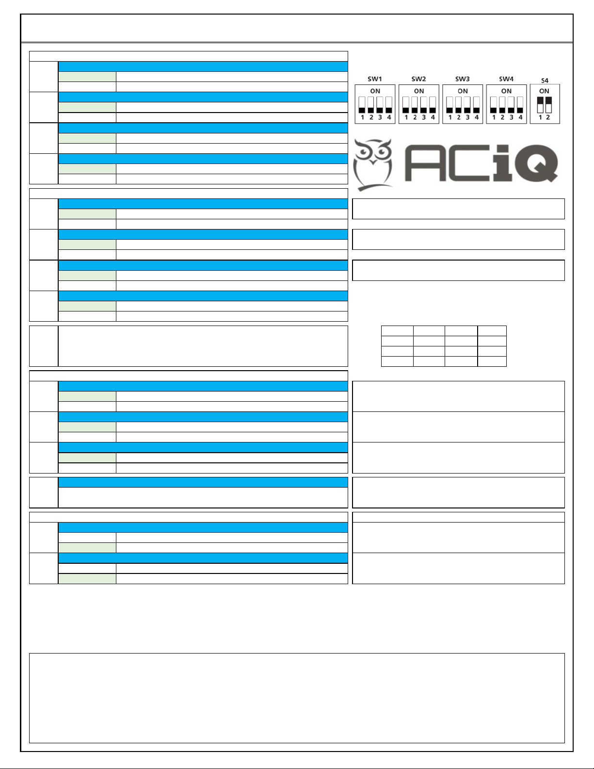
1= -4 °F 5= 10 °F 9 = 25 °F D= 39 °F
2= 0 °F 6= 14 °F A= 28 °F E= 43 °F
3= 3 °F 7= 18 °F B = 32 °F F = 46 °F
4= 7 °F 8= 21 °F C= 37 °F
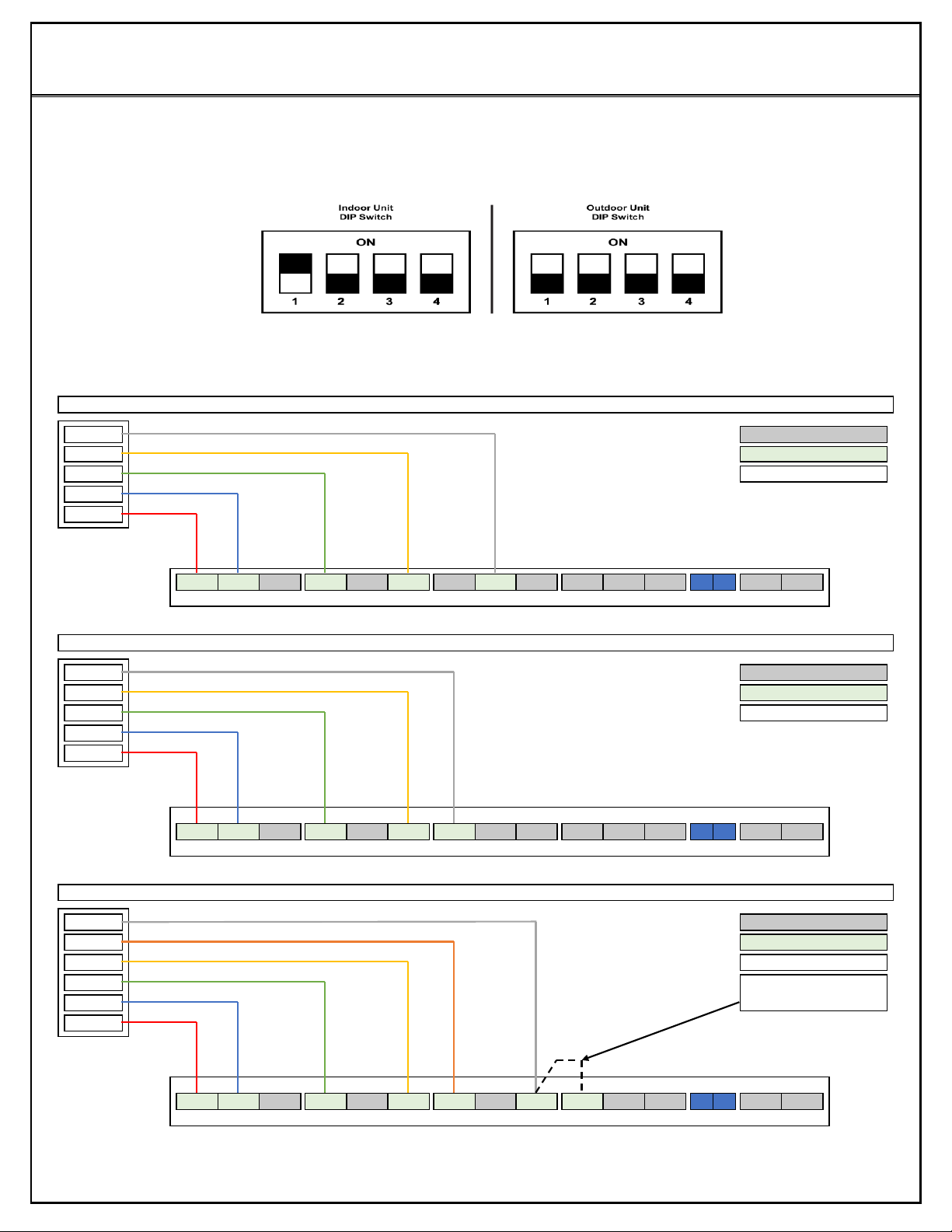
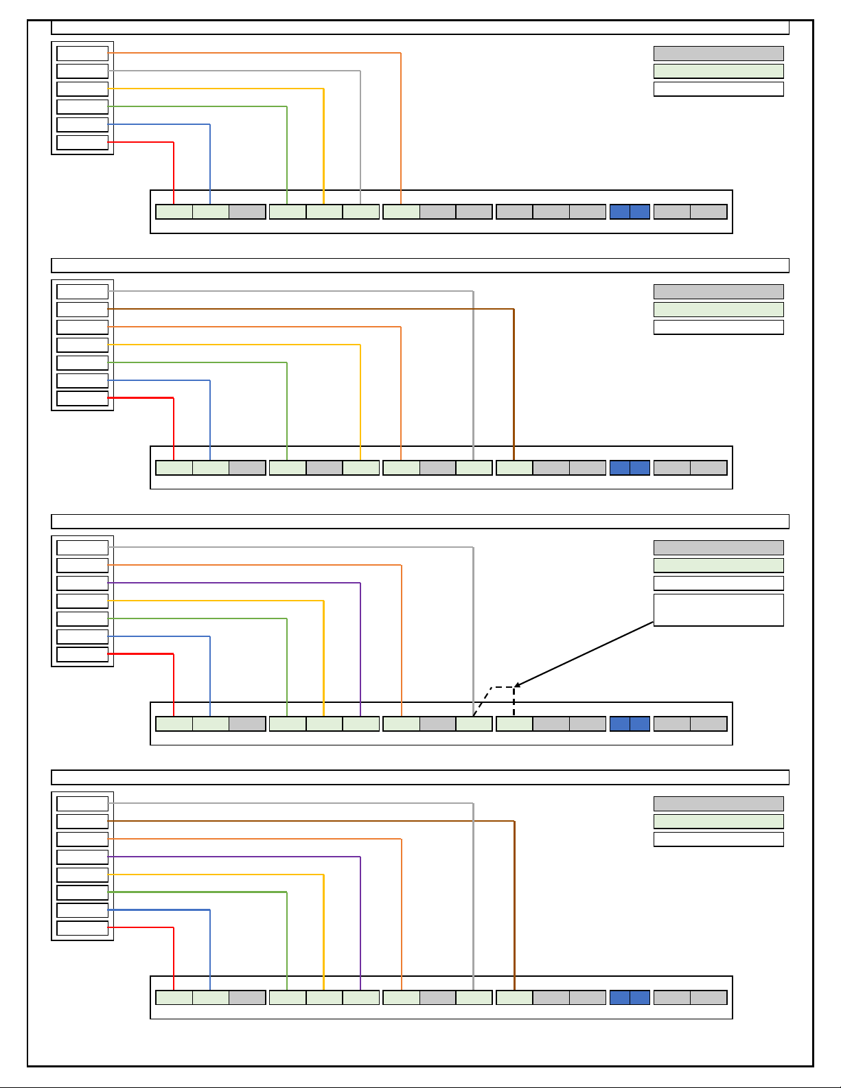
Please note if using the provided ACiQ thermostat DIP Switch Settings will not need to be adjusted. DIP Switch settings should
only be adjusted by a professional HVAC service technician. Please note in this quick start guide the specific DIP Switches that
need adjusted will be shown to ensure accurate operation for the chosen set up. For Option 1 nothing needs to be done. For
Option 2 please refer to the DIP Switch diagram that shows the correct position of the DIP Switches.
W1 & W2 Controlled Separately
W1 & W2 Not Controlled Separately
SW4
Electric Heat Nominal CFM Adjustment
Delay between 1st stage & 2nd stage electric heat is time based,
not temperature based.
This sets the maximum continuous runtime allowed before the
system automatically stages up capacity. Only applies if 24 volt
thermostat is being used.
S4-2
DH Terminal Available To Be Used
S4-1
This sets minimum temperature, anything under this setting locks out.
This sets maximum temperature, anything over this setting locks out.
SW3-3
W2 Temperature Differential Activation
15 Minute Delay (For Electric Heat)
30 Minute Delay (For Electric Heat)
SW3-2
Y/Y2 Temperature Differential Adjustment
24 Volts. Used For Third Party Thermostats.
Cold Air Prevention - Defrost
If selected 24 volt thermostat has an E/AUX option and it is used
to activate heat, all delays will be bypassed.
SW3-1
Ramping Up Algorithm Delay
SW2-3 only works if SW2-2 is turned ON.
SW2-4
In This Position Electric Heat Lockout Can Be Set Via ENC2
In This Position Compressor Lockout Can Be Set Via ENC2
SW2-3
Auxiliary Heat Activation Delay Time
SW1-1
SW1-2
SW1-3
SW1-4
Thermostat Communication Method
RS-485 Communication. Used For Provided ACiQ Thermostat.
Cold Air Prevention Activated - Fan Stops
No Cold Air Prevention - Fan Continues To Operate
Default setting is OFF except S4.
For example [SW4-1 OFF, SW4-2 ON, SW4 -3 OFF] = 010
T1 Sensor = Return Air Temp (Room Temp), Ts = Set point
This DIP switch only works if using the provided communicating
ACiQ thermostat. Otherwise delay is time based.
Available settings are 000/001/010/011. Each digit corresponds with an
individual switch position.
If using 24 volt thermostat this sets compressor speed instead.
ON = slower, OFF = Faster.
IMPORTANT: In order for changes to take effect power must be OFF BEFORE DIP switch changes.
Default AHU DIP Switch Settings Shown Below
When auxiliary heat is energized the fan will run in Turbo Mode.
ENC2 Dial Referenced In SW2-4. 16 Digits To Select From (0-9, A-F). Lock Out Range = -4
°F to 46 °F. 0 = No Lock Out, 1 = -4 °F Lock Out, F = 46 °F Lock Out. Each Digit Increases
Temperature By 3.6 °F. Chart Provides Temperature Rounded To Nearest Whole
S3
SW2-1
Auxiliary Heat Activation Differential
4 °F Gap Between T1 & Ts Sensors
2 °F Gap Between T1 & Ts Sensors
SW2-2
Auxiliary Heat Activation Delay