FEATURESDESCRIPTION
Turbo/Short Run
Parking lights flash threetimes
OFF
Turn off theignition key,
the engine will keeprunning.
Exit and secure thevehicle.
Press button for 0.5sto
arm and lock thecar.
The engine will turnoff after
the programmed run time.
Park the vehicle andset parking brake.
Remove your foot fromthe brake pedal
and leave the enginerunning.
1.In this mode, thesystem will start theengine every 3 hours,for a maximum ofsix cycles. Theengine will
run for the programmedrun time and thenshut down to keepengine warm in thecold weather.
2.The remote start command can shut down theengine in timer mode,but the system willremain in the
timer mode.
3.To exit timer mode, press button 0.5s to disarm thesystem, turn the ignitionkey on and thenpress the
brake pedal or press button 0.5s and thenbutton 0.5s again.
4.If any other shutdown zones or alarmhas been triggered, thetimer mode will cancel.
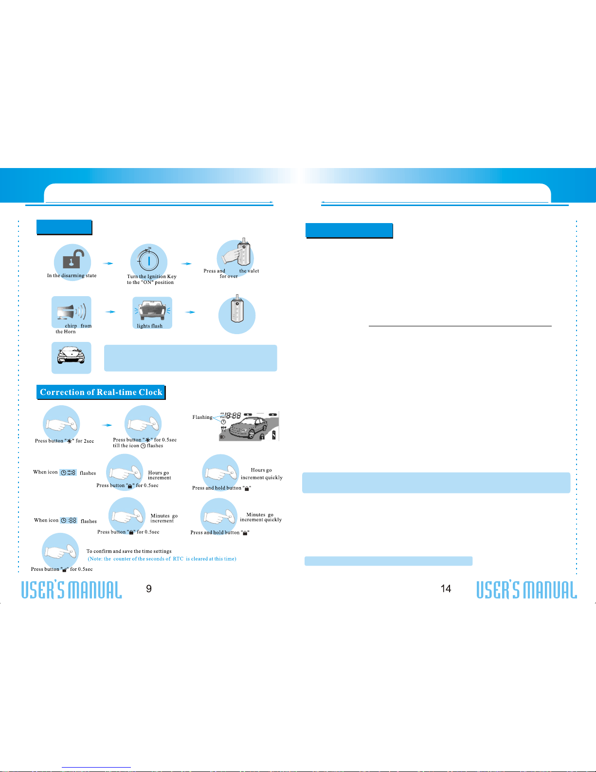
Remote StartTimerMode
Press button for 0.5s.
Parking The system willenter
Remote Start TimerMode
Four
four times
Turn on
Note: Once you activatethe short-run turbo mode,the system will remainthis mode always. Ifyou don t
want this mode anymore, press button againto cancel it anytime.
+
Flashing slowly
+
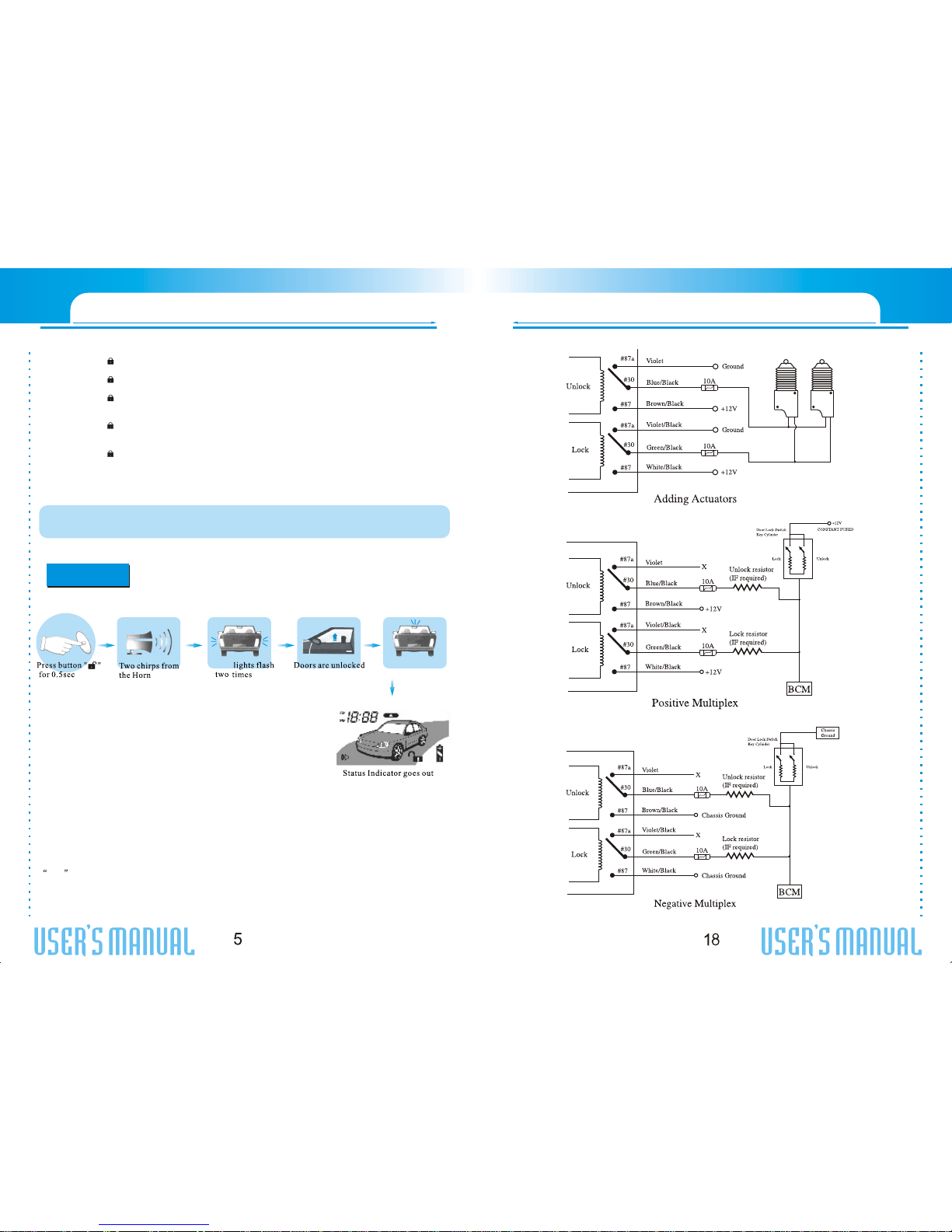
Pin4: Blue/Black:Unlock #30 Common (Output)
Pin5: Brown/Black:Unlock #87 Normally Open(Input)
Pin6: Violet/Black:Lock #87a Normally Closed
Pin7: Green/Black:Lock #30 Common (Output)
Pin8: White/Black:Lock #87 Normally Open(Input)
Pin9: Red:Constant +12V Input.Connect this wire tothe battery or ConstantPower wire at theIgnition
Switch with a 15AmpSupply.
Pin10: Black:System Ground. Connect thiswire firmly to theChassis Ground.
6-pin Secondary Harnessfor Outputs(H2)
Pin 1: ORANGEWIRE: Armed Output (-) 500mA.The orange wiresupplies a ground outputwhile armed
to activate a relayfor starter defeat andanti-grind protection.
Pin 2: BLUEWIRE: Second unlock (passenger unlock)output(-) 200mAThis system is equippedwith a
dedicated passenger unlock outputallowing two stage doorlock operation. Whenconnected this wire,
disarming the system willunlock only the drivers door. Pressingthe disarm button againwill unlock all doors..
Pin 3: WHITE/BLACK WIRE:Auxiliary Channel 5Output (-) 200mA. Thiswire provides a (-)200mA
output whenever the transmitterbutton is pressed for2S. This outputcan be programmed toprovide the follo
wing types of outputs:
a.0.8-second timed: Outputthat will send aground pulse of 0.8second.
b.15-second timed: Outputthat will send aground continuous pulse for15 seconds.
c.Latched,reset with ignition:Output that will senda signal when theChannel 5 button (button ) is pressed and
will continue until thesame button (button )is pressed again. Itadditionally stops output wheneverthe ignition
is turned on.
Pin 4: PURPLE/BLACKWIRE: Auxiliary 4 Output (-)500mAfor windows rolling-up option.Connect to
a power window module.
Pin 5: BLACK/WHITEWIRE: Dome Light Output (-)500mA. Connect to thewire that activate thevehicle's
dome light, usually thedoor pin switch wire.Note: the dome lightoutput can usually connectto the same wire
used for the doortrigger input (see purpleand green door inputwire).
Note: This outputis only intended todrive a relay. It can notbe connected directlyto the dome light
circuit, as theoutput cannot support thecurrent draw ofone or morelight bulbs.
Never use thiswire to driveanything but a relay or alow-current input. Thetransistorized output
can only supply 200mAof current. Connectingdirectly to asolenoid, motor,or other high-current
device will cause itto fail.
Pin 6: RED/WHITEWIRE: VehicleTrunk Release Wire (-)500mA. Connect thiswire to the electronic
trunk opener. (Relaymay required).
8-pin 2510 Harnessfor Inputs andOutputs(H3)
Pin 1: GREEN/BLACKWIRE: Factory Disarm Output (-)500mA. This wireprovides a ground outputon
disarming and before remotestarting to disarm afactory security system. Connectto the wire thatrequires a
ground pulse to disarmthe factory security system.
Pin 2: GREEN/WHITEWIRE: Factory Rearm Output (-)500mA. This wiresupplies a ground outputon
remote start shutdown torearm a factory securitysystem. Connect to thewire that requires aground pulse to
rearm the factory securitysystem.
Pin 3: BLACKWIRE: Optional Sensor Input (-).Connectto an optional instantsensor such as trunkpin switch.
SYSTEM INSTALLATION
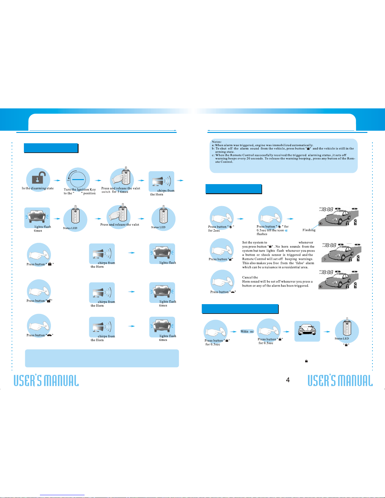
In arming state
Three chirps from theHorn