CASK ACS V4.2 User manual

Automated Canning
System V4.2 Manual
CASK BREWING SYSTEM INC.
Third Edition, November 2016
ACS V4.2
Toll Free: 1-800-661-8443 Direct: +1 403-640-4677 Fax: +1 403-640-4680 e-mail: info@cask.com
Technical Service & Support Parts Order
1-800-661-8443 Option #4 1-800-661-8443 Option #4
Official supplier of Ball Corporation for the supply of printed aluminum cans to our customers
cask.com

www.cask.com
+1-800-661-8443
Third Edition, Nov 2016
ACS V4.2
Page | 1
Confidential
Automated Canning System (ACS) V4.2 Manual
Third Edition, September 2016
Copyright
© 2016 Cask Brewing Systems Inc. All rights reserved.
Disclaimer
The information presented in this manual has been reviewed and validated for accuracy. The included set of instructions
and descriptions are accurate for the Cask Brewing Systems Inc. Automated Canning System Version 4.2 (ACS V4.2) in its
stock condition as supplied by Cask Brewing Systems Inc., at the time of this manual's production. However, subsequent
products and manuals are subject to change without notice. Therefore, Cask Brewing Systems Inc. assumes no liability for
damages incurred directly or indirectly from errors, omissions, or discrepancies between any subsequent or altered
products and this manual.

www.cask.com
+1-800-661-8443
Third Edition, Nov 2016
ACS V4.2
Page | 2
Revision History & Document Control
Manual
Version
Release
Date
System
Updates
First Edition
August
2011
ACS V4.0
Initial Manual Release.
Second Edition
February
2014
ACS V4.1
Updated electrical section for new V4.1 panel design.
Expanded Frequently Asked Questions section.
Third Edition
November
2016
ACS V4.2
Formatting update.
Can Seam Evaluation videos added.
Updated Parts List.
Expanded “Can Table Height Adjustment”section
Future Updates
As we evolve future iterations of this Manual, we will post the most recent versions and updates on-line at our website.
www.cask.com/customer-login/
Password: CaskCustomer
Note: you will also require the below username to download the PDF version of the manuals.
Username: CaskCanning123

www.cask.com
+1-800-661-8443
Third Edition, Nov 2016
ACS V4.2
Page | 3
Table of Contents
Section A. Before You Begin............................................................................................................................................. 4
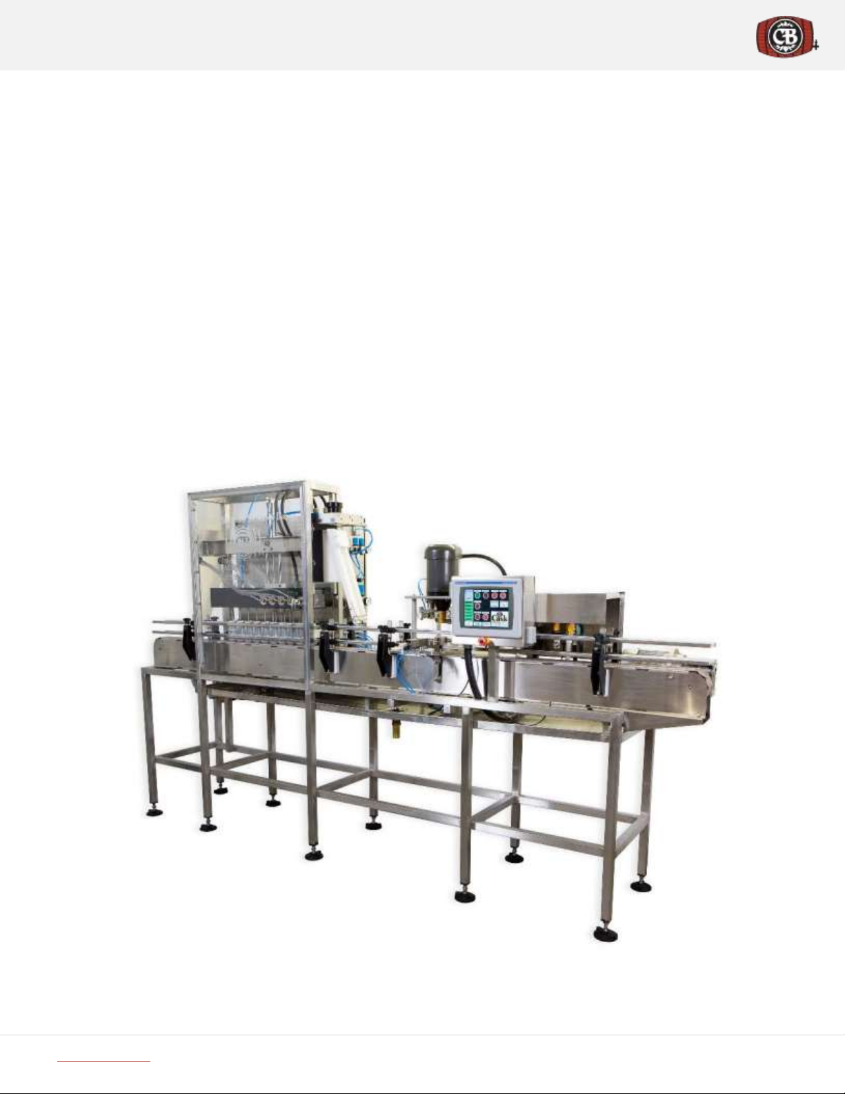
A.1 Unit Diagram ........................................................................................................................................................... 4
A.2 System Requirements ............................................................................................................................................. 4
Section B. Unit Setup ....................................................................................................................................................... 5
B.1 Uncrating Requirements ......................................................................................................................................... 5
B.2 Uncrating Procedure ............................................................................................................................................... 5
B.3 Packing List / Loose Parts ........................................................................................................................................ 6
B.4 Initial Adjustments & Settings................................................................................................................................. 6
B.5 Unloading Cans ....................................................................................................................................................... 7
Section C. ACS Operations Overview ............................................................................................................................... 9
C.1 System Operation Walkthrough ............................................................................................................................. 9
C.2 Controllers............................................................................................................................................................... 9
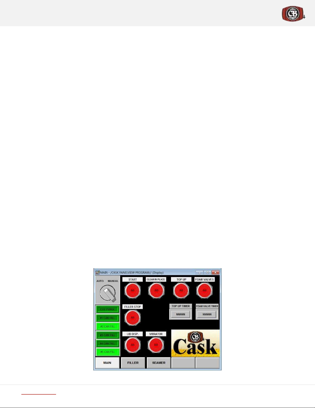
C.3 HMI Control Panel Operations .............................................................................................................................. 12
C.4 Electrical Panel Overview...................................................................................................................................... 13
C.5 Can Filling .............................................................................................................................................................. 18
C.6 Lid Dispenser ......................................................................................................................................................... 19
C.7 Parts in Motion: Pneumatics................................................................................................................................. 19
C.8 Parts in Motion: Motors........................................................................................................................................ 20
Section D. ACS System Operations................................................................................................................................. 22
D.1 Initial Start-up Adjustments & Settings ................................................................................................................ 22
D.2 Pre-Start Checklist................................................................................................................................................. 22
D.3 Startup & Operation.............................................................................................................................................. 23
D.4 Clean in Place (CIP) System ................................................................................................................................... 23
D.5 ACS Post-Operation Shutdown Checklist.............................................................................................................. 24
D.6 System Periodic Maintenance .............................................................................................................................. 25
D.7 Parts List................................................................................................................................................................ 25
D.8 Adjustment & Troubleshooting ............................................................................................................................ 27
D.9 Frequently Asked Questions ................................................................................................................................. 32
Section E. Seam Measurement.......................................................................................................................................... 37
E.1 Can Seam Evaluation Training Videos................................................................................................................... 37
E.2 Manual Seam Evaluation Process ......................................................................................................................... 38
E.3 Reading a Seam Micrometer................................................................................................................................. 38
E.4 Seam Measurement.............................................................................................................................................. 39
E.5 Seam Troubleshooting .......................................................................................................................................... 42
E.6 Seam Specifications .............................................................................................................................................. 42
Section F. Can Seamer ....................................................................................................................................................... 43
F.1 Seamer Adjustment & Troubleshooting ............................................................................................................... 43
F.2 Seamer Troubleshooting....................................................................................................................................... 47
F.3 Bearing Replacement ............................................................................................................................................ 47
Section G. Safety ............................................................................................................................................................ 49
Section H. Warranty Information ................................................................................................................................... 50
Section I. Company Information ....................................................................................................................................... 51

www.cask.com
+1-800-661-8443
Third Edition, Nov 2016
ACS V4.2
Page | 4
Section A. Before You Begin
A.1 Unit Diagram
Figure 1 Automated Canning System - Unit Diagram
A.2 System Requirements
Figure 2 Top View - Canning System Requirements –all hookups except drain on backside of unit

www.cask.com
+1-800-661-8443
Third Edition, Nov 2016
ACS V4.2
Page | 5
Section B. Unit Setup
B.1 Uncrating Requirements
Recommended Tools
Bolt cutters or large pair of wire cutters to remove metal bands
Pry bar (recommend 2)
Claw hammer
Freestanding 10’ Ladder
Forklift
Cordless drill with Robertson/Phillips bit
B.2 Uncrating Procedure
Refer to Figure 4 Uncrating your new Cask ACS.
Inspect crate exterior and document any damage incurred in transit
Cut metal bands and remove from exterior of crate
Use pry bars to remove plywood covering each end (Figure 4 –Step 1)
Next remove plywood skin from top of crate (Figure 4 –Step 2)
Leave end supports and remove all top cross supports with hammer
Brace sides or have someone hold them in place and remove last top cross supports
Gently fold sides of crate down to the floor (Figure 4 –Step 3)
You now have unfettered access to contents
Figure 4 Uncrating your new Cask ACS
Figure 3 In case you’ve never seen a crate before
1
2
3

www.cask.com
+1-800-661-8443
Third Edition, Nov 2016
ACS V4.2
Page | 6
Section B. Unit Setup
B.3 Packing List / Loose Parts
Inside the container you’ll find the following items packed along with the main machine
Lid Cage
Conveyer Catch Tray
Tool kit
Twist rinser (if ordered)
Spare parts package (if ordered)
Darex Manual “Evaluating and Controlling Double Seams Manual”
B.3.1 Moving Unit into Position
After removing bands and holding blocks securing canning machine to pallet base, use forklift (lift truck) to move
main unit into position (refer to unit footprint Figure 2 for clearances).
Protect stainless finish by placing wood on lifting forks to prevent metal-on-metal contact.
Spread forks so lifting points are as close to welded joints as possible to prevent bending cross supports.
Slide lifting forks under lower supports centered on balance fulcrum of unit which is located on center of the
machine.
Figure 5 Forklift moving Cask ACS into position
B.4 Initial Adjustments & Settings
Your Cask canning line has been factory tested prior to shipping to allow for trouble free installation by a Cask Technical
Representative at your site.
Your warranty period will also commence at the date of installation and commissioning by a Cask Technical Rep.
Prior to arrival of your Cask Technical Rep, you should complete the following initial machine setup:
•Inspect overall machine shipping damage.
•Level machine in final production position.
•Have qualified electrician connect the machine to plant power (refer to C.4 Electrical Panel ).
•Connect machine to compressed air supply (see Table 1).
•Connect machine to plant CO2 system (see Table 1).

www.cask.com
+1-800-661-8443
Third Edition, Nov 2016
ACS V4.2
Page | 7
Section B. Unit Setup
•Connect machine to cold water supply (see Table 1
•Also recommended to have hot water access nearby machine for cleaning.
B.4.1 Machine Specification Sheet
Your Cask ACS will require the following utilities.
Power
208/230 volts, 50/60 Hz, 40 amps, 3 phase
Electrical connection to be hardwired inside panel by certified electrician
Compressed Air
18 cfm at 125 psi
Require a 7.0 peak HP, 50 gal/200L tank c/w refrigerated dryer and autofloat drain for Depal
and ACS combined operation.
Cask recommend compressor is CompAir L05 FS –200 (23.66 CFM-0.67 mᶟ/min).
Water Supply
½” cold water line – garden hose connection (testing)
½” hot water line – nearby machine (CIP)
CO2Supply
20psi from plant system connected to machine with 3/8” barbed fitting
Drainage
Drainage is required from the canning table to drain (standard 1 ¼” waste pipe connection)
Beer
1.5 –2” beer line from dispense tank.
Beer supplied to machine at a temperature of 32 to 35.6 F (0 to 2 C).
Forklift
To unload the equipment on arrival
Table 1 ACS Machine Specifications
B.5 Unloading Cans
The cans come stacked up to 8’9” high on Pallets (Figure 6 - A).
The cans are very fragile and are subject to denting and damage in handling so be very careful.
Verify straps are undamaged before moving full pallet.
Resist impulse to touch stack or cans as damage will result.
Each pallet footprint is 44” x 56”.
A single truck load of cans contains up to 25 pallets of cans.
Storage –Can be stacked 4 high, height permitting. One container load of cans on pallets require roughly 374
square feet of floor space.
The lids for an entire container load of cans are on a single pallet (Figure 6 - B).

www.cask.com
+1-800-661-8443
Third Edition, Nov 2016
ACS V4.2
Page | 9
Section C. ACS Operations Overview
C.1 System Operation Walkthrough
This section details the steps and procedures you’ll need to familiarize yourself with in order to operate the ACS. This
includes all functions and the effect of every switch and button on the machine. The following is a brief breakdown of the
line’s operation. Beginning at can in feed and following through to finished product out feed.
The conveyer belt carries cans to the first gate. The gate, just after the fill head, has a dual function, A) stopping
and holding cans under the fill head, and B) opening just long enough to allow the five filled cans to pass after fill
cycle.
The fill head waits for ten cans to accumulate underneath it before lowering. The first set of five cans are filled
with beer. The second set of five cans are purged with CO2. When the beer level reaches the sensors the fill stops,
the head rises, and the gate opens to allow the 5 filled cans through and stops the 5 purged cans under the raised
fill tubes.
The filled cans leave the gate, pass under the lid dispenser where the leading edge of each can grabs a lid as it
passes under the slide, pulling a lid onto the top of each can. The area immediately under the lid dispenser and
the dome under the can lid are purged with CO2 during the process.
Cans then stop at the block before the #1 push cylinder. This block acts both to stop the flow, and trigger the
cylinder to push the can onto the seamer lift table. This sensor also triggers the lid dispenser to drop another lid
into the lid slide tray.
Once on the lift table the can is raised into the chuck, which rotates the can. The #1 die pushes into chuck making
the first seaming operation, followed by #2 which completes the seam, then the lift table lowers.
The lowered can is pushed off the lift table by the oncoming can and deposited in front of the #2 push cylinder,
which pushes it onto the out feed conveyer which carries it through the washer/dryer (if installed), after which
the final product is carried to the end of the process, the collection table.
C.2 Controllers
C.2.1 HMI Panel –Main Page
Main screen to start the seamer motor and the belt. Also, controlling CIP, Top Up, Foam Valves, Lid Dispenser. Main Screen
has integrated timers for better production monitoring while filling.
Figure 7 HMI Panel –Main Page screenshot

www.cask.com
+1-800-661-8443
Third Edition, Nov 2016
ACS V4.2
Page | 10
Section C. ACS Operations Overview
Button/Switch
Manual/Auto
Function
Manual/Auto
Both
Switches between auto and manual
CO2 Purge
Auto
Indicates when pre-purge is open
#1-5 Can Fill
Auto
Indicates when valves are open
Filler Stop Button
Auto
Normal stop of the filler operation in auto mode
(seamer continues to run)
Lid Dispense
Both
Dispenses a lid
Clean in Place Indicator
Switch (CIP)
Auto
Lights up when clean-in-place running; Turn the
clean-in-place function on or off
Top Up Indicator Switch
Auto
Lights up when top up is running; Turn top up on or
off, depending on position
Top Up Timer
Auto
Sets the amount of time the top up will last for
Foam Valves Indicator
Switch
Auto
Lights up when foam valves running; Turn foam on
or off, depending on position
Foam Valve Timer
Auto
Sets the amount of time the foam valves will be on
for
Start Button
Auto
Start the equipment in auto mode; Lights up when
running
Vibrator Off/On Switch
Both
Turn on the shaker or depal table vibrator
Table 2 HMI Panel –Main Page –Button Functions
C.2.2 HMI Panel –Filler Page
Manually Control Can Fill, CO2 Purge, Gate, Lid Purge.
Figure 8 HMI Panel –Filler Page screenshot

www.cask.com
+1-800-661-8443
Third Edition, Nov 2016
ACS V4.2
Page | 11
Section C. ACS Operations Overview
Button/Switch
Manual/Auto
Function
CO2Purge Button
Manual
Opens CO2pre-purge
No. 1-5 Can Filling
Buttons
Manual
Opens valves on both beer spouts at the
numbered position
Gate Button
Manual
Opens can gate on conveyor
Conv. Motor Off/On
Switch
Manual
Starts or stops the conveyer, depending
on position
Lid Purge
Manual
Opens under lid gas purge
Filler Cylinder Button
Manual
When held down the fill head will lower
fill head into the down position, when
released the fill head will return up
Pre-rinse
Manual
Opens pre-rinse water supply
All Can Fill Button
Manual
Opens all 5 fill stations
Table 3 HMI Panel –Filler Page –Button Functions
C.2.3 HMI Panel –Seamer Page
Manually Control all aspects of the seamer. Table Up/Down, Die1/2 in-out, Push Cylinder #2, Seamer Motor Control.
Figure 9 HMI Screen –Seamer page screenshot

www.cask.com
+1-800-661-8443
Third Edition, Nov 2016
ACS V4.2
Page | 12
Section C. ACS Operations Overview
Button/Switch
Manual/Auto
Function
Seamer Motor
Manual
Turns seamer motor on
Table Cylinder
Manual
Operates table cylinder (up/down)
Push Cyl. 1
Manual
Operates can push cyl. #1
Push Cyl. 2
Manual
Operates can push cyl. #2
Dryer
Manual
Turns dryer on
Washer
Manual
Turns washer (post-rinse) on
Test Die #1
Manual
For testing 1st roll seam thickness
Test Die #2
Manual
To produce a test seam
Lid Dispense
Both
To dispense a lid
Die #1
Manual
Move seaming roll #1 in and out
Die #2
Manual
Move seaming roll #2 in and out
Table 4 HMI Screen –Seamer –Button Functions
C.2.4 Below Touchscreen
The emergency stop button is located under the touch screen for easy access.
Figure 10 Emergency Stop and Power Buttons
Button/Switch
Manual/Auto
Function
Emergency Stop Button
Both
Immediately stops the system from operating,
and pneumatics return to their rest positions
Main Switch (behind
machine)
Both
Main power supply switch
Table 5 Manual buttons located below the touchscreen
C.3 HMI Control Panel Operations
There are two different operating modes that the ACS can operate in and it is important to understand both of them, why
they both exist and when you should be in which mode.
C.3.1 Manual Mode
Manual mode is generally used for setup and troubleshooting purposes. Most of the buttons and controls you see on the
unit will only work while in manual mode. It allows for the discreet control of each individual operation and allows you to
perform step-by-step operation of the machine to see and evaluate each process individually.
You would typically use this mode when adjusting the seamer or troubleshooting individual system functions.

www.cask.com
+1-800-661-8443
Third Edition, Nov 2016
ACS V4.2
Page | 13
Section C. ACS Operations Overview
C.3.2 Auto Mode
Auto mode is selected for either regular operation (filling and seaming cans) or CIP (cleaning the machine before and/or
after use). While in Auto mode manual buttons on the three screens will not work, with the following exceptions:
1. Lid dispense (to allow you to replenish lids in the slide tray)
2. Top-up button (to allow you to turn top-up on and off and control the duration of the top-up (timer))
3. Foam valves (to allow you to turn foaming on and off and control the duration of the foam creation(with the
timer))
4. Fill stop (to allow you to stop filling while continuing to seam remaining cans (filler will continue to fill cans that
are in the filler but will not begin the next fill cycle, cans will continue seaming))
5. E-stop (to immediately cease all operation)
C.4 Electrical Panel Overview
C.4.1 Top Row of Breakers
Figure 11 Top row of breakers
POWER
SUPPLY
CONVEYOR MOTOR
SEAMER MOTOR
VIBRATOR
PLC
RELAYS
PANEL

www.cask.com
+1-800-661-8443
Third Edition, Nov 2016
ACS V4.2
Page | 15
Section C. ACS Operations Overview
Relays
1. SYSTEM AUTO SEQUENCE
2. SYSTEM MANUAL SEQUENCE
3. START CONVEYOR MOTOR
4. START SEAMER MOTOR
5. START DRYER SOLENOID
6. WASHER SOLENOID
7. PRE RINSE SOLENOID
8. CO2 PURGE LID DISPENSER
9. CO2 PURGE CANS
10. BEER VALVE 1A
11. BEER VALVE 2A
12. BEER VALVE 3A
13. BEER VALVE 4A
14. BEER VALVE 5A
15. BEER VALVE 1B
16. BEER VALVE 2B
17. BEER VALVE 3B
18. BEER VALVE 4B
19. BEER VALVE 5B
20. FOAM VALVE 1
21. FOAM VALVE 2
22. FOAM VALVE 3
23. FOAM VALVE 4
24. FOAM VALVE 5
Figure 13 Relay wiring diagram

www.cask.com
+1-800-661-8443
Third Edition, Nov 2016
ACS V4.2
Page | 16
Section C. ACS Operations Overview
C.4.2 Beer Manifold
Beer should be carbonated to 2.4 to 2.9 volumes of CO2 (or 4.6 to 5.6 g/L).
Beer Temperature of 0 –2C or 32 –35.6F (colder for higher CO2 volumes).
CO2 supply to bright tank should be set at 13 –15 PSI (depending on CO2 volume, temperature and distance from
dispense tank).
In order to fill a can, the first step required is to have your product connected to the machine. The manifold allows a single
hose line (1.5” tri clamp connection) to be connected from your tank to the machine, and then splits it ten ways to supply
each valve in the fill head. The valves are rated to a maximum pressure of 24 PSI, so it is important not to exceed that line
pressure or fill valves will fail to open. In Figure 14 you can see the two sets of five supply lines that are connected to the
valves in the fill head, as well as the single supply line from the tank.
Best practise is to install a temperature and pressure gauge on the end of the beer manifold to allow monitoring of
temperature and pressure of the beer at the delivery point to the machine.
Figure 14 Beer Manifold
C.4.3 Fill Head Manifold
The gate downstream of the fill head stops the cans creating a backlog all the way to the shaker table (Figure 15). This
backlog is important as the spacing of spouts in the fill head are based on the cans being right up against each other. There
are 10 cans under the fill head. The last 5 are purged with CO2 as the first five (already purged) are filled with beer. After
the fill is complete the head retracts to the up position and the gate opens. The sensor immediately upstream of the gate
counts 5 cans before re-closing the gate and beginning the next fill cycle.

www.cask.com
+1-800-661-8443
Third Edition, Nov 2016
ACS V4.2
Page | 18
Section C. ACS Operations Overview
C.4.4 Foam Valve and Top Up Setting
C.4.4.1 Foam Valve & Button
In order to keep air pick up to an absolute minimum the beer must be foaming when it leaves the filler until the
lid is applied at the lid applicator. Generally the level of foam should be at or over the top of the can rim when the
lid is applied.
If the foam level on the beer is low, additional foam can be created by activating the foaming valve.
When the foaming valve button is turned on, the timer below this button controls the length of time that the foam
valve will create foam. Generally, only a very short setting is required to create foam. We set this at 0.1 to 0.2
seconds to begin. Run through several beer fill cycles to establish whether the foam is sufficient before increasing
the timer setting. To set timer: press timer button, enter time, hit enter button to save change. Timer can be
changed at any time during operation –the new time will not take effect until the next fill cycle starts.
Note: Never turn the foam valve button on or off while the fill valves are open and filling. This will cause a
malfunction of the level sensors.
C.4.4.2 Top Up Setting
When the Top Up button is turned on the fill valves will shut off as usual when the level sensors detect foam BUT
–they will reopen for a period of time –determined by the adjacent top up timer –while the valves are being
withdrawn from the can.
This Top Up function gives the operator further control of the final fill level of the can. The beer that leaves the fill
spout as the spout is rising with the fill head replaces the volume of the spout itself –raising the final fill level. This
may prove necessary with beers that are excessively foamy during the fill, leaving too much head space in the can
once the initial foam recedes. The top up function can also be used to create a small amount of additional foam
(due to the turbulence created as the beer flows into the filled can) to beers that foam too much when the foam
valves are used.
To operate: turn the foam valve on when the fill heads are at rest. Set the timer to 0.25 seconds. Run a few can
fill cycles to gauge the effect. Increase the time interval as required.
Note: When setting interval on top up timer, be sure that beer valves are not still open (verify visually during
operation) when the valve has exited the top of the can as this will result in oxygen pick-up.
C.5 Can Filling
The two primary functions of your canning system are filling an empty can with beer, and seaming a lid onto the filled can.
This section is a useful reference understanding how the machine accomplishes these two functions. It is necessary to
understand the filling process and your choices associated with it regarding foam. The seaming process is very important
to the on-shelf quality of your product. Without the proper seam in place your cans could leak, spoil, or go flat before the
beer gets to the customer resulting in wasted product and decreased revenues. For this reason it is very important to both
understand the seaming process and how to evaluate your seams once made.
As previously discussed under Section C.4.2 Beer Manifold (page 16), the first step required is to have your product
connected to the machine. The beer passes through the manifold to the ten valves in the fill head. The first five empty
cans stop directly beneath the fill heads five fill stations. Each station has two fill spouts, one with a foam valve, one
without, and a fill level sensor. The fill head then drops down inserting both spouts and sensors into each can. If you desire
more foam in the can, set the system for it with the foam timer on the HMI Panel. The switch must be set to the on position
and the desired foaming time set on the timer dial. When the foam button is on the fill sequence begins with a burst of
foam from the foam valve for the duration set on the foam timer. Regular filling then continues until the cans are full.
Once the beer/foam level reaches the sensors the corresponding valves will close and filling will stop for that fill station.

www.cask.com
+1-800-661-8443
Third Edition, Nov 2016
ACS V4.2
Page | 19
Section C. ACS Operations Overview
Each station has independent sensors to compensate for slight variances in fill time. Once all five sensors read full and all
fill spouts have stopped, the head rises out of the can and the gate opens allowing five cans to pass through it.
C.6 Lid Dispenser
The lid dispenser holds the lids at the optimum angle for contact with the cans passing underneath on the conveyer –refer
to 1 in Figure 17.
The leading edge of each can grabs and pulls a lid out, which falls into place on top of the can, as it passes. CO2 is dispensed
beneath the lid to purge air from the top of can. A new lid is dropped into the tray for every can that comes into contact
with the position sensor at #1 push cylinder.
Lids can be manually dispensed using the “Lid Dispense” button on the Seamer Panel (see Figure 9 on Page 11).
For more information regarding adjustment and troubleshooting, refer to Section D.8.1 Lid Dispenser Adjustment &
Troubleshooting on Page 27 and D.9.2 Lid Dispense Troubleshooting on Page 34.
Figure 17 Lid dispenser
C.7 Parts in Motion: Pneumatics
All of the cylinders on the machine are run pneumatically. Having a general understanding of how these are set up is
important. The actuators, valves, and most of the regulators are contained behind the back panel of the equipment. With
the door open you will see something similar to the Figures below.
1
2
3
Table of contents
Popular Brewing System manuals by other brands

Grindmaster
Grindmaster AT-2W Brochure & specs

BrewBuilt
BrewBuilt X1 UNI Assembly and Instruction Guide

BRAVILOR BONAMAT
BRAVILOR BONAMAT Aurora Single Low OPERATING PRINCIPLE

MB
MB Medusa GEN2 QuadHead CounterPressure Bottle... Operation and maintenance guide

BREWFERM
BREWFERM rvs 27 l operating instructions

Keurig
Keurig K150 owner's manual