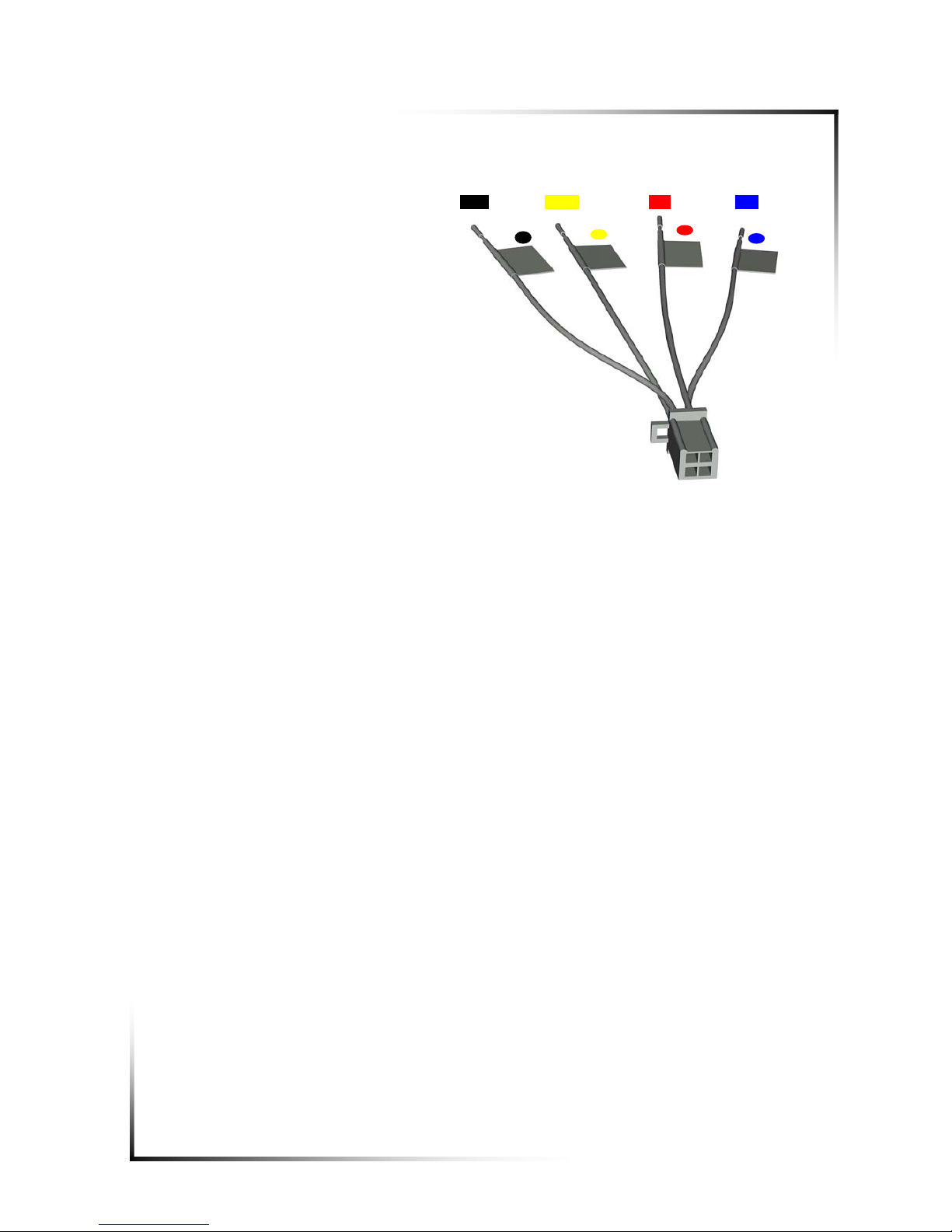
CDD Ural Concert User manual

Customizable Digital Device
Automobile CD-MP3 receiver
Version 0.96 Ma
y
2005 www.СDD.ru
USER MANUAL
Specifications
Certification information
Guarantee policy


ATTENTION!
When purchasing:
•make sure that the receiver has no mechanical damage and ask for its
functional check
•make sure that guarantee and tear-off cards specify works number, release
date, store stamp, decipherable signature or stamp of the sales person and
date of sale. Remember that in case you lose the guarantee card you forfeit
your right to guarantee repair
•check the receiver’s completeness
•check the safety of protective stamp on the receiver’s frame and make sure
that Personal Unblocking Code (PUK-code) indicated on the back-page of
the “User manual” is not broken
After repair:
•Ask for the receiver’s functional check being performed in your presence
•Check the availability of protective stamp on the receiver’s frame, ripping of
the tear-off card and the mark of the fulfilled works indicated on the back of the
guarantee card
Carefully study the content of this User Manual, this will allow to
reduce the time of the receiver’s parameters installation and
tuning and to avoid errors that can damage the receiver and other
components of the audiosystem.
To avoid the receiver’s breakdown, its installation into an automobile should be
performed in a specialized positioning center or workshop.
The receiver shall be supplied by the automobile’s board net with the nominal voltage
of 14.4V and the car body’s minus sign.
The receiver is meant for use in GOST 15150 conditions, in category 2.1 moderately
cold climate, in this regard the lower operating air temperature shall not be lower than
+1 ○C, transportation and storage temperature shall be from -30 ○C to +60 ○C.

General information
URAL ConceRt automobile CD-MP3 receiver is developed and made in
Russia under CDD (Customizable Digital Device) project. The purposes of CDD
project included and include development and market introduction of original digital
devices enabled to change the stereotyped image of functionality, method of
construction and use of widespread domestic electric appliances.
Concept
URAL ConceRt CD-MP3 receiver (hereinafter referred to as receiver) was
developed as a programmable device not limited by the traditional framework of
rough hardware functionality, oriented toward its possible update and broadening by
means of embedded software change and toward the user’s possible soft adjustment
of numerous behavioral and acoustic parameters and possible personification.
Architecturally, the receiver is a multiprocessor embedded system controlled
by the multitask real time operational system with special peripheral of automobile
acoustic use.
Characteristics
The receiver’s functionality is largely represented by its software, that is why to
say that the receiver is excessively functional or does not have enough functions is
the same thing as to form you attitude to a computer by its installed and operating
programmes. The task of this User Manual is not only to describe in detail the
application programme performed by the receiver, but to describe the receiver’s
potential in terms of this programme. It goes without saying that the description of
functionality (performed in programme terms) cannot go without the description of the
programme performing this functionality, but this description shall not make the
impression on the user that the receiver has limited functions or that the functions are
strictly predetermined. The receiver’s software (as distinct from its hardware) and, as
a consequence, its functionality will undergo a number of considerable changes.
Version types
The receiver can be supplied in two main versions differed by the absence or
presence of embedded power amplifiers. All version specifications (excluding power
amplifier section) are identical, constructionally the version without embedded power
amplifiers differs by the absence of radiator at the receiver’s backplate (and as a
consequence, by the size), by the absence of cable with PA output connector and by
the specific value of main fuse (3A instead of 15A). This User Manual contains the
description of version with embedded amplifiers.

Basic functions
Audio
•24-bit DAP, 24-bit ADC
•Line input (stereo) + microphone input (stereo)
•6 independently controlled line inputs (7V) + subbuffer input
•6 power amplifier channels (max: 4х45 W + 2х35 W)
•6 DSP-treated independent channels
•6 independent high-accuracy hold-up channels
•Embedded 3-lane crossover (cut-off rate 12/24 dB/oct)
•Embedded graphic one-third-octave (30 lanes) or equivalent parametric equalizer
Independent stereo base control for three pairs of stereo channels
•Embedded test and measuring signals generator
•
CD-section
•Media: СD-DA, CD(-R,-RW)
•File control systems: multisession ISO9660/Joliet, UDFS*
•Compression formats: (AD)PCM, WAV, MP3, Vorbis*, FLAC*
•СD-Text (CD-DA), Tags (for compressed formats)
•Electronic antishock (including that for CD-DA)
FM-radio
•Digital programme and hardware radio signal processing
•FM(stereo) and VHF (stereo) bands
•FM synthesizer’s frequency spacing 10 kHz
•RDS and Radiotext* system support
•Random station choice option
•Fragment repeat mode (without information loss)
User interface
•Graphic VFD-display
•Tentative one-button control" (encoder)
•Multimedia animation menu
•Multilanguage font and code support (UNICODE-16)
•Voice informer
•Distance control desk (widespread desk support)
Attachment interfaces
•Embedded automobile diagnose interface (Electronic document management
system)
•MegaBUS fast-speed interface (5Mbps):
oATAPI BOX*: ATA-accumulator support (HDD, ATAPI-CD/DVD)
oComputer connection
oTransmitter connection

Software support and update
Embedded software update performed by the user
Reprogrammable menu, options, animation
Development engineer feedback (development engineer’s Internet site)
Additional service options
On-board computer mode work
Nonvolatile memory of all settings
Embedded real time clock
Calendar, alarm-clock, timer/time check
Notebook, Dictaphone, games*
Safety
Power saving timeouts
"Hands Free"* option
Motion parameters * monitoring
Many-level anti-thief protection system

Distance
control desks
Positioning frame
Faceplate case
Measuring microphone
Faceplate
Base unit
Installation
kit
Cable and power connector
Cable and power
amplifier connector
Escutcheon
Delivery set
Base unit with escutcheon 1 item
Faceplate in a case 1 item
Distance control desk 2 item
Measuring microphone 1 item
Cable and power connector 1 item
Cable and power amplifier connector 1 item
Positioning frame 1 item
Attachment sections set 1 set
User manual 1 item
Additionally delivery set may include:
•Demo disk
•Owner’s club card
The set is delivered in the original package (metal case).

Installation and attachment. Recommendations.
The receiver’s automobile installation and attachment shall be performed by a
qualified expert. In case you have no relevant skills, you should consult a specialized
positioning center. Before commencement of work switch off the negative side of the
accumulator battery.
Composition and purpose of the receiver’s external connectors.
1
2
3
4
5
6
SUB
LINE IN
Line inputs
MIC
L
R
Yel Red
Red
Red Red Wh
Wh
Wh
Wh
MIC IN
Microphone input
Line tagging
Cable length 30сm
15A
Safety cutoff
ANT
Aerial connector
POWER
Power connector SPEAKER
Power
amplifier inputs
DATA
Digital interface
connector
•
Line tagging
Cable length 15сm
LINE OUT
Line inputs

GROUND +12V
POWER +12V
MEMORY ANT/PAMP
CONTROL
Black Yellow Red Blue
Power connector (POWER)
In order to connect power to the
receiver, use the cable with the
power connector counterpart
included in the delivery set.
Connect the black line
(GROUND) to the car body in one
of the places provided for by its
construction. When choosing
connection point, try to minimize
the length of the connecting line.
Provide safe electric contact in
connection joints for major current
flow (up to 15A).
Connect the yellow line (+12V
POWER) with the car +12V circuit
(current up to 15A) thus providing
safe and quality connection. It is
recommended to connect this circuit directly to the accumulator battery positive side.
In order to optimize operation of embedded power amplifiers, use connecting line of
increased section for the receiver’s power circuits (GROUND и+12V POWER) and
try to minimize its length. When the receiver is switched off, the current consumed in
this circuit does not exceed 10mA.
In case the yellow line (+12V POWER) is connected to the power circuit not
switched off from accumulator battery, the red line (+12V MEMORY) can be not
switched (in this case it should be isolated). In case by some reason the yellow line
(+12V POWER) is connected to the circuit with the switched-off voltage (for example,
when the key is removed from the ignition lock), connect the red line (+12V
MEMORY) to the circuit not switched off from the automobile accumulator battery. It
is required for consistent operation of real time clock when the receiver is switched
off. The current consumed in the circuit does not exceed 10mA.
The blue line (ANT/PAMP CONTROL) is used to control power or switching of
additional devices (active or automatic aerial, external power amplifier, etc.). The
voltage of this input (+12V, filtered from powerful unwanted signals) appears in
several seconds after the receiver is switched on. In case the total current consumed
in this circuit exceeds 0,7A, use an additional relay (is not included in the delivery
set). The circuit has an electrical protection from exceeding the current-carrying
rating. When the protection responses (it is determined by indirect indicators), it is
required to switch off and to restart the receiver in several seconds.

1 2 3 4 5 6
gray white blue violet brown green
Power amplifier input connector (SPEAKER)
In order to connect
acoustic systems (AS) to the
receiver, use the cable with the
power amplifier input connector
counterpart included in the
delivery set.
In order to reduce power
loss at the AS circuit resistance,
use the line of increased section
and try to minimize its length.
Minimum permissible acoustic
systems resistance shall be 4
Ohms.
When connecting the AS it
is desirable to observe the power
amplifier’s signal phase (polarity),
to this effect each “holdout” line of each 6 cable line pairs is marked by a black strip.
In case phasing errors are found (after the receiver’s installation is completed),
correct the phase (Menu->Sound->Invertor).
Optionally (after the system’s installation is completed) it is possible to change
the channel switching, i. e. its numbers (Menu->Sound->Commutator).
When installing multilane (crossover) audio system, it is recommended to use
the receiver’s embedded crossover instead of external passive junction filters (Menu-
>Sound->Crossover). This will improve audio quality and increase the efficiency of
power amplifier use (see Recommendations on acoustic performance section).
Attention!
Power amplifier cables of the fifth and sixth channels of receivers with
C00xxxx serial numbers have erroneous polarity marking. When connecting
AS, it is necessary to exchange the lines in each pair of brown (fifth channel)
and green (sixth channel) lines.
Receiver aerial connector (ANT)
Connect the standard automobile aerial cable connector to the receiver’s ANT
connector. Make sure that the connectors make tightly, are not dirty or oxidized.
In spite of taking complex measures on screening of the receiver’s digital part, it
is the source of unwanted signal in the radio reception exclusive band, that is why
operation it is not recommended to work with standard types of inter-compartment
active aerials. If possible, use an external whip aerial fixed on the car’s roof or boot.

Digital interface connector (DATA)
In order to organize interfaces with different external digital devices the receiver is
provided with 8-contact DIN-type connector. DATA connector’s counterpart in not
included in the receiver’s delivery set and shall be purchased separately.
Composition and location of the connector’s signals are shown in the figure and
in the chart:
RELAYx and K-LINE signal functions
shall be determined by the programme and
can differ significantly in various installation
types. The user shall determine the specific purpose of function of these signals and
some of their parameters (Menu->Settings->Interfaces*).
RELAY1(2)
digital (threshold) inputs for slowly changing external signals. Are generally meant
for connecting contact transmitters or automobile automatics circuits. RELAY1(2)
signal switching thresholds are fixed, RELAY1 input active state is low, RELAY2
input active state can be changed by the user with the help of the programme.
RELAY3
universal digital (threshold) input for receiving of external signals at the speed of
up to 100KBps.
Switching thresholds are programmable (5V or 2,5V).
K-LINE
two-headed “K” tire (open collector) in accordance with ISO 9141 standard.
Primary purpose is emulation of diagnostic equipment for automobiles with
Electronic engine control system (EECS). Switching thresholds (5V or 2,5V) and
load resistor are installed by the user with the help of the menu. Apart from the
primary purpose (K-LINE EECS), K-LINE signal can be used as a general purpose
input or output for external device interface organization at the speeds of up to
100KBps.
MEGA_x
specialized two-headed speed MegaBUS tire (up to 10MBps) meant for control
and connection with remote intellectual digital devices of information collection,
# Signal Purpose
1 RELAY2 Relay input 2
2 GND Signal ground
3 K-LINE K-Line input/output
4 MEGA_A MegaBUS tire
5 MEGA_B MegaBUS tire
6 RELAY1 Relay input 1
7 RELAY3 Relay input 3
8 GNDS Screening ground
- SHIELD Screening ground
2
4 5
1 3
8
6 7
SHIELD
DATA connector (socket)
output-side view

storage and processing. The number of tire devices depends on their purpose and
can reach ten.
All interface signals are protected from back voltage and (direct) voltage
overloading, nevertheless, when connecting, it is required to observe common safety
precautions (to check the signals compatibility according to voltages and currents
levels, commutations shall be performed when the power of all the devices is
switched off, to avoid signal inter-bridging, on the ground or power circuit). It is
recommended to connect external signals to the DATA connector in one of
Authorized Service Centers.
Line output connectors (LINE-OUTx and SUB-OUT)
In order to connect external power amplifiers, the receiver is provided with six
high-voltage line outputs and subbuffer amplifier output (RCA connector type).
Output stages of line output signals are made on speed low-noise operating
devices with low output resistance and short circuit protection.
In order to obtain maximum Signal/Noise ratio of the audio system that uses
external power amplifiers, it is required to coordinate their responsitivity with the
voltage of the receiver’s line outputs with the help of external power amplifier GAIN
regulator. In some cases the coordination may require installation of 2:1 resistance
divider at the power amplifier output.
Line input connectors (LINE-IN)
In order to connect external audio signal sources, the receiver is provided with
line input RCA-connectors (stereo input). Responsitivity of line inputs (the level of
digital amplification) can be controlled by the programme (Menu->Settings->Input).
Microphone input connector (MIC-IN)
MIC-IN connector (stereo 3.5mm Phone Plug) is meant for connection of
measuring stereo microphone included in the delivery set. In order to reduce noise
and phone that can appear in some mixing modes, the microphone amplifier can be
switched off (Menu->Settings->Amplifiers).

Operating modes, screens
In operation the receiver can be in one of the modes generally determined by the
current data source and internal programme and hardware configuration.
Operating mode:
Mode Data source
1 FM FM-radio
2 CD embedded CD-drive
3 LIN line input/microphone
4 AUX* external source (for example, HDD-accumulator)
5 LAB generator/measurement
6 ECU on-board computer
7 BLK block signaling (mode without data source)
8 ERR accident condition (hardware or software breakdown)
1-4 modes are basic (operation with audio data sources). The following combined
modes are also possible:
9. FM + LIN (+ECU)
10. CD +LIN (+ ECU)
11. AUX + LIN (+ ECU)
12. LIN + ECU
Mode transition can be performed according to the user’s signals (or actions) and
can also be the consequence of definite (including accidental) events. The examples
of mode changing conditions are: preset time oncoming, timeout expiration, CD-disk
loading/unloading, faceplate removal, key turn in the ignition lock, switching off or
malfunction of the external data source, change of parameter controlled by the on-
board computer, repeated erroneous password entry, hardware or software failure.
In any mode (besides BLK and ERR)in the process of data processing or under
the user’s control, the receiver can change its states and these changes are
accompanied by showing relevant user screens at the faceplate display.
Screen types:
•Menu
•Settings screen (menu)
•Main screen (of the data source)
•Emergency screen (of the data source)
•Settings screen (of the data source)

•Screen examples
Upper level menu
First enclosed level menu
Settings screen (menu)
Main screen of FM-radio source
Main screen of CD source
Emergency screen (of CD source)
Emergency screen (of FM-radio source)
Settings screen (of FM-radio source)

Control bodies
The receiver provides full and easy control of all functions with a minimal set of
control bodies. The size and location of control bodies are carefully planned and it
allows to use them “at random” not straggling from driving.
For each control body or its combination there exist a number of simple, easily
rememberable modulations providing optimal access to all the receiver’s functions in
all its operating state and modes. The most useful and usable control operations are
performed by the simplest modifications – short pressings.
The receiver’s control is mainly intuitive, i. e. any time a definite modification lead
to the most desirable result. The receiver’s definite modification response is
contextual, i. e. it depends on the operating mode and the current state in this mode.
In order to simplify the random control, some important events (source change, input in
operating nested menu, etc.) are accompanied by an audio signal (BEEP) of the dynamic
embedded in the receiver (the BEEP volume does not depend on the volume of the whole
system).
Control bodies composition:
•Encoder (twist handle with an imbedded button)
•“ESC” button (big key located at the left side of the faceplate)
•“EJECT” button (disk eject button located at the inner side of the faceplate)
•“REL” buttons (faceplate changeover button, mechanical function)
•Distance control desk buttons
REL
Encoder
DC infrared receiver window
ESC
EJECT

Modification types:
Encoder
•turn
•short pressing
•long pressing
•pressing and turn
•double pressing
“ESC” button
•short pressing
•long pressing
•double pressing
"EJECT " buttons short pressing
•DC desk
buttons
•single pressing
•double pressing
Combinations
•simultaneous pressing of “ESC” button and encoder
•simultaneous pressing of "EJECT" button and encoder
•simultaneous pressing of "EJECT" and “ESC” buttons
Notes:
Turn (of the encoder):
This is the most commonly used modification (main parameter
regulations are performed by the encoder’s turn). For easy regulations the
encoder’s handle has a big diameter and is supplied with a number of inside
and outside lugs allowing to make a turn with one or several fingers. Besides,
in order to reduce regulation time (when the ranges of tunable parameters are
large), the encoder’s responsiveness increases on condition that it actively
and continuously rotates during a definite period of time (thus, for example, the
accelerator switches on).
Pressing:
The receiver responds to pressings (and turns with a pressing) when
the button is released. Any pressing is considered short if it does not exceed
~1,5 sec. Any longer button holdup is considered to be a long pressing. The
majority of short pressings and all long pressings are accompanied by a short
BEEP signal, besides, shortly before making a long pressing the receiver’s
display starts to change its brightness in a smooth and repeated manner.
Any pressing is considered double if a pause between two short pressings
does not exceed ~1sec.
Pressing with a turn is a short pressing on the encoder when the encoder’s
handle is turned sideward before release of the encoder.

Main modification functions:
Function Modification
Switching on •Long pressing on the encoder
Standard switching off
•Simultaneous pressing of “ESC” button and the encoder
•Double pressing of Distance control desk red button
•Selection and use of “Switching off” menu command
•Taking off the faceplate
Source change
•Double pressing of “ESC” button
(on the main screen of the current source)
•Pressing of relevant Distance control desk buttons (“CD”,
“Tuner”,..)
Switch over to the main
screen of the main
Source
•Double pressing of “ESC” button
(not on the main screen of the current source)
•Pressing of Distance control desk green button
Sound Muting/Unmuting
and иCD-mode pause
•Short pressing of “ESC” button
•Pressing of Distance control desk “Mute” button
Current time
announcement
•Long pressing of “ESC” button
•Pressing of Distance control desk “Voice” button
Fragment repeat in FM-
radio mode
•Double pressing of the encoder
•Pressing of Distance control desk “Repeat” button
Menu entry •Pressing with a turn (of the encoder)
•Pressing of Distance control desk central "О" button
Deleting of the last
symbol in entry line •Short pressing of “ESC” button (in entry line mode)
Non-standard
(emergency) switching
off
•Simultaneous pressing of " EJECT " button and the encoder
Emergency disk eject •Simultaneous pressing of " EJECT " and “ESC” buttons
Notes:
Operative functions and modifications are marked gray.
Less operative functions are activated from the main screens by the encoder’s
short pressing, more remote and rarer settings and navigations are activated
by the encoder’s long pressing (see “Function formal description”).

Distance control desks
The receiver’s delivery set
contains two standard IR-desks
with different versions and number
of buttons.
The receiver supports
simultaneous operation of two
different distance control desks,
the user can use desks of other
models and manufacturers, apart
from the standard desks (or
instead of them).
The receiver is compatible
with desks using 36...38 KHz
carrier frequency and RC-5,NEC
or semiNEC modes for
transmission.
Functions of all buttons of any
desk can be set (reset) on the
setting screen (Menu->Settings-
>Distance control desk).
By default the standard desk
buttons are marked in accordance
with the functions most commonly
used in the receiver. Functionality
of some buttons can insignificantly
differ in various modes. Some
buttons and their main functions are listed bellow:
Power off
(red button) Playback mode selection
Return to the main screen of the current screen
(green button) Album selection
Switch over to RM-Radio source Time announcement
Switch over to CD source Style selection
Show “Clock” screen (trigger) Change of display brightness
Sound muting / CD pause (trigger)
Navigation through radio stations and tracks Menu entry (the desk’s central button)

Recommendation on control modes
The encoder is a mechanical regulator and is exposed to wear. Do not apply extra
force when working with the encoder, try to use it only when necessary and prefer to
control the receiver with the help of distance control desk.
In case over 10 seconds passed after the receiver’s standard switching off, it can
be switched on only by the encoder’s long pressing, otherwise the receiver can be
also switched on by pressing the distance control desk red button.
The sound volume (of audio sources and the informer) is regulated by turning the
encoder only on the audio sources’ main screens and on the clock screen. On other
screens turning of the encoder exercises other functions.
Use “double pressing of ESC button” modification in order to turn over to the main
screen from any other screen.
Sound muting/unmuting functions and CD-player pauses are activated by a short
pressing of ESC button and are available in all audio modes and subsidiary screens,
except the entry screen of the user text line: on this screen a short pressing of ECS is
used for deleting the last symbol of the line.
Current time announcement is activated by a long pressing of ESC button. The
announcement takes several seconds, during the announcement the display shows
the clock screen automatically changed by the current main screen. Sound volume
control during time announcement cancels turn over to the main screen.
Use “the encoder’s double pressing” to repeat the last 10 seconds of the radio
programme. To compensate time loss when playback is rolled 10 seconds back,
playback speed is increased (and then is slowly reduced) till synchronization with the
programme real time. ‘R sign located in the upper line of FM-Radio source main
screen indicates the repeat mode of the receiver. After time lag compensation is
completed (in approximately 40 seconds), the receiver automatically logs off the
repeat mode. The repeat mode is interrupted by pressing of any button (in this case
information loss is inevitable). Sound volume control does not interrupt the repeat
mode.

Menu, modes and functions. Formal description.
User interface and most of the receiver’s functions are activated by the
programme. When the software is updated, some interface functions, as well as
control modes and procedures can be changed and (or) widened, including changes
and widening occurred by the users’ suggestions (see. www.cdd.ru ). Besides, like
any computer system, the software can have errors and in the course of time shall be
modernized. Further description implies the user’s understanding of these receiver’s
characteristics and is basically oriented toward general understanding of user
interface organizational principles and the receiver’s control strategy.
Menu
Abundance of functions, controlled parameters and user settings and
numerous screens ask for structuring of printed information and unification of its
access. The menu embedded in the receiver helps to organize and simplify required
information control and access process to a considerable extent. It is a set of
hierarchically connected sections and items shown on the display as formalized icon
pictures associated with different modes, parameter set or command. Turnovers
between menu items are visually represented as animation for the sake of menu
navigation convenience and its positioning. The menu has several hierarchy levels.
Menu entry is available any time from any mode or screen.
Operation Faceplate DC desk
Menu entry
pressing with a turn central button
Traverse through one-level
menu items
turn “right” and “left” buttons
Traverse through menu
levels
short pressing (down)
long pressing (up) “up” and “down” buttons
Menu exit to the main
screen of the current source ESC double pressing of ESC button green button
Notes:
•Menu level is displayed in the indicator’s right upper corner by the respective
number of signs (the sign is not displayed for upper/zero level, one sign is
displayed for the first embedded level, etc.)
•Traverse to the menu upper level by the encoder’s long pressing is accompanied
by the level sign flash.
•After selection of the required menu item the encoder’s short pressing leads to
the transfer to the relevant setting screen
Table of contents