Celeros EzSAN XL Series User manual

Celeros EzSAN XL Series
Manual (Ver. 1.15) February 05, 2007

2
1
Before you get started ..............................................................................4
1.1 Supported clients .................................................................... 4
2
Features ...................................................................................................5
2.1 What is Celeros EzSAN XL Series? .................................................. 5
2.2 Why XL Series?........................................................................ 5
2.3 Description of the functions........................................................ 5
2.4 XL Series Benefits ....................................................................
2.5 XL Series feature summary .........................................................
2. RAID types.............................................................................
3
Conf gurat on ............................................................................................7
3.1 The basic configuration of the EzSAN XL Series ................................. 7
3.2 First-time operation of Celeros XL Series ........................................ 7
3.3 Logging into Celeros XL Series ..................................................... 8
3.4 Create Disk Array .................................................................... 9
3.5 Adding Disk Array ...................................................................10
3. Creating XL Series, iSCSI target volumes ........................................12
3.7 Configuring end user workstation ................................................13
3.8 How to connect iSCSI in Windows 2000/XP/2003:.............................. 13
4
Manage XL Ser es us ng console funct ons ............................................15
5
Manage XL Ser es us ng browser funct ons ............................................16
5.1 SETUP ................................................................................. 1
5.1.1 Network ........................................................................1
5.1.2 Administrator..................................................................21
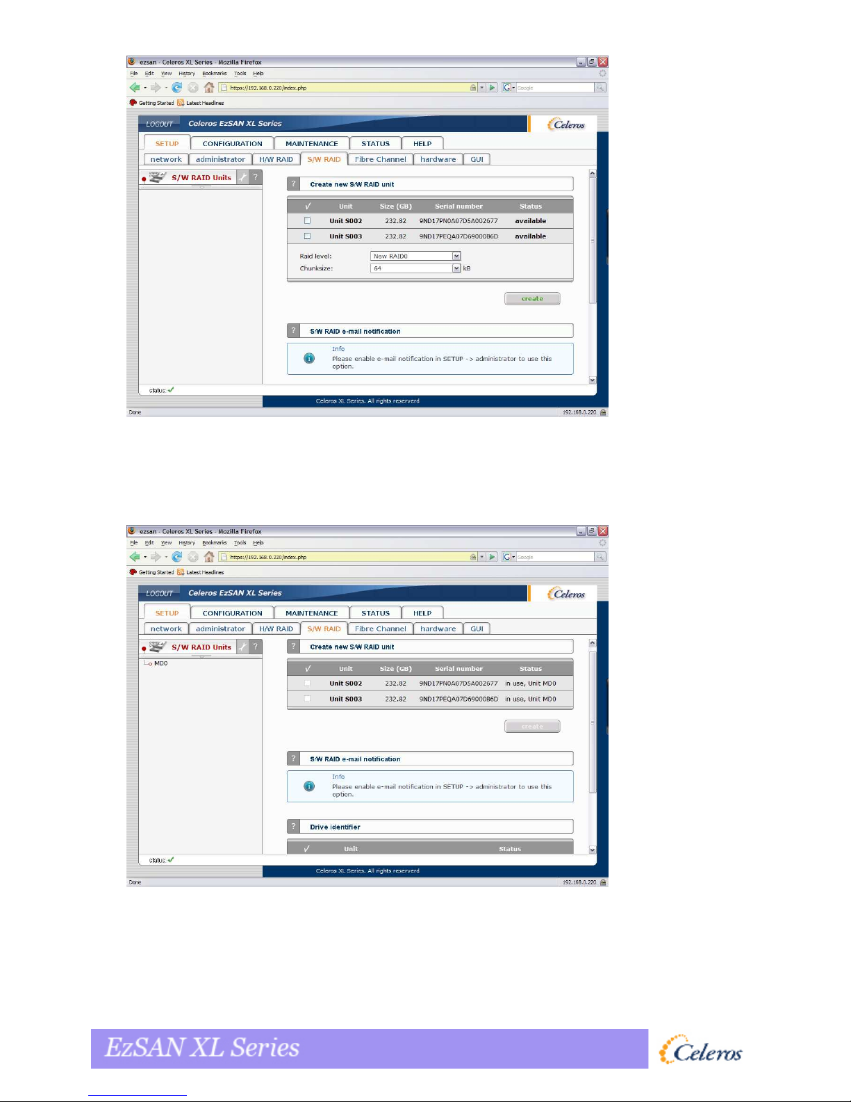
5.1.3 S/W RAID.......................................................................2
5.1.4 Fiber Channel .................................................................30
5.1.5 iSCSI Initiator..................................................................31
5.1. Hardware ...................................................................... 32
5.1.7 GUI..............................................................................35
5.2 Volume manager .................................................................... 3
5.2.1 Volume Groups ................................................................3
5.2.2 Volume replication ........................................................... 40
5.2.3 ISCSI target manager ......................................................... 42
5.2.3.1 Targets ................................................................42
5.2.3.2 Chap users ............................................................4
5.3 MAINTENANCE .......................................................................47
5.3.1 Shutdown ......................................................................47
5.3.2 Connections ...................................................................48
5.3.3 Snapshot .......................................................................49
5.3.4 Miscellaneous..................................................................50
5.3.5 Software update ..............................................................52
5.4 STATUS ...............................................................................53
5.4.1 Network ........................................................................53
5.4.2 Connections ...................................................................54
5.4.3 Hardware ......................................................................55
5.4.4 S.M.A.R.T. .....................................................................58
5.5 HELP ..................................................................................59
5.5.1 Software License.............................................................. 59
5.5.2 About Celeros XL Series...................................................... 0
6
Troubleshoot ng Gu de ...........................................................................62
7
Append x A .............................................................................................63
8
Append x B .............................................................................................65

3
Copyright
(c) 2004, 2005, 2006, 2007 Celeros Corp. All rights reserved. No part of this
pu lication may e reproduced or transmitted in any form, y any means, electronic,
mechanical, copying, recording or otherwise, without the prior written consent of
Celeros Corporation.
Trademarks
EzSAN®, EzNAS®, EzSANFiler®, Celeros XD Series®, Celeros XF Series® Celeros
XL Series®, Celeros XN Series®, Celeros XR Series® and Celeros XW Series® logos
are all registered trademarks of Celeros Corporation.
Windows®, Microsoft®, Apple®, Pentium® and Intel® are registered trademarks. All
other trademarks herein are property of their respective owners.
Disclaimer
Celeros Corporation assumes no responsi ility for errors or omissions in this
document, and Celeros Corporation does not make any commitment to update the
information contained herein.

4
1 Before you get started
Congratulations on purchasing Celeros XL Series, the ideal solution for network-based storage
management. This manual will assist you as you install and configure your storage appliance.
In order to uickly reach the desired configuration, please read the following pages thoroughly.
The time invested is well spent - after all, you have purchased this solution for your invaluable
data.
1.1 Supported cl ents
• Microsoft Windows (all versions)
• Linux
• Unix
• Mac OS X

5
2 Features
2.1 What s Celeros EzSAN XL Ser es?
Celeros EzSAN XL Series is based on iSCSI (internet SCSI) Technology; it is a protocol that
encapsulates SCSI (Small Computer System Interface) commands and data into TCP/IP
packets for linking storage devices with servers over common IP infrastructures. By using
iSCSI, you can supply high performance SANs (Storage Area Networks) using standard IP
networks like LAN, MAN, WAN or the Internet.
XL Series Contains its own Operating System so you don’t need to install one, in fact we
strongly advise against the installation of a separate OS on the Celeros XL Series unless
instructed to do so by Celeros staff.
XL Series allows users the ability to add additional disk devices to existing networks uickly,
easily, and cost-efficiently.
XL Series is based on client-server architecture. Clients of an iSCSI interface are called
"initiators". Initiators issue iSCSI "commands" to re uest services from components, logical
units, of a server known as a "target". The "device server" on the logical unit accepts iSCSI
commands and processes them.
To learn more about the history and benefits of iSCSI, see Celeros iSCSI White Paper at
http://www.celeros.com/pdf/iscsi_whitepaper.pdf
2.2 Why XL Ser es?
XL Series is ideal for demanding IT environments that re uire a combination of high
performance, high-end features, and low cost. While it is as simple to configure XL Series as
other series, has the addition of Multiple Snapshots, Online Volume Expansion and
Replication among other features. XL Series runs on all Celeros SAS/SATA Platforms and
presents an ideal entry point for growing organizations that re uire cost effective storage that
can grow with their needs.
2.3 Descr pt on of the funct ons
Celeros EzSAN XL Series is one of the easiest ways of implementing an Storage Area Netowk
(SAN) and/or an iSCSI technology in your network.
Assign an IP address to your Celeros EzSAN XL Series to begin working, all you need to do is
to either automatically through an existing DHCP server or by assigning it manually. All other
settings are handled via a web GUI which can be easily accessed through the IP address of
Celeros EzSAN XL Series using the encrypted https protocol.
Celeros EzSAN XL Series allows users to allocate volumes and iSCSI Targets to be mounted
from any servers using iSCSI initator on the network.

2.4 XL Ser es Benef ts
With Celeros EzSAN XL Series, you can:
♦ Add storage to your existing environment uickly, easily, and most important,
cost-efficient.
♦ Consolidated storage and back ups for multiple servers.
♦ Improved data availability and efficiency.
♦ Reduced costs by the centralization of storage management.
♦ Simplify the on-going installation and management of storage.
2.5 XL Ser es feature summary
♦ Hardware based RAID levels 0,1,3,5,6,10,50,60
♦ Online volume expansion
♦ UPS support
♦ Network Fault Tolerance
♦ Adaptive load balancing
♦ Multiple scheduled snapshots
♦ Synchronous mirroring
♦ Replication
♦ Support for a wide variety of hardware and s/w initiators
♦ Celeros XL series can improve existing setup performance by centralizing storage
for a shared use of resources and processing power “effectively”.
2.6 RAID types
This manual is not intended to replace your RAID controller manual. But we want to provide
you with an overview of common RAID types so that you can make an informed decision on
which type to choose. Depending on whom you ask, RAID means either Redundant Array of
Independent Disks or Redundant Array of Inexpensive Disks. Both are correct. In essence,
you combine the capacity, speed and security of several disks into one.
RAID 0 forms one large hard disk by concatenating stripes from each member drive. Stripe
size is configurable roughly between 64 KB and 1 MB. The result is a lightning-fast RAID,
but with no added security. One failing drive may ruin the entire RAID.
RAID 1 mirrors hard drives. By writing identical data onto more than one drive, security is
enhanced. A completely defective drive does not cause any loss of data. The drawback is
reduced performance and capacity.
RAID 5 combines data striping from RAID 0 with parity checking, therefore combining speed
and improved security. The loss of one drive is tolerable.
RAID 6 extends RAID 5 by adding an additional parity block, thus it uses block-level striping
with two parity blocks distributed across all member disks. It was not one of the original
RAID levels. The user capacity of a RAID 6 array is N-2, where N is the total number of
drives in the array. RAID 6 does not have a performance penalty for read operations, but it
does have a performance penalty on write operations due to the overhead associated with the
additional parity calculations.
RAID 10 is a combination of RAID 1 and 0, hence the name. Data is written in a striped and
mirrored configuration, providing high performance and robust security.

7
3 Configuration
3.1 The bas c conf gurat on of the EzSAN XL Ser es
Connect the keyboard and monitor (they will be needed for setup only). Later you can run the
server in the "headless mode" (without keyboard and monitor).
3.2 F rst-t me operat on of Celeros XL Ser es
Now start your system.
After booting is complete, Celeros XL Series will provide you with information on the
current software version and the network settings and it should appear as follows:
Welcome to Celeros XL Series Press F1 for Help)
-----------------------
Model: Celeros XL Series
Version: 2.00.IE20000000.2438
Release date: 2006-12-11
S/ : 87654321
etwork settings:
Interface 1: eth0 IP: 192.168.0.220/255.255.255.0
Interface 2: eth1 IP: 192.168.1.220/255.255.255.0
HTTPS settings:
port: 443
allow from: all

8
If the network has a DHCP server, Celeros XL Series should gain access to the IP settings
automatically. If that is the case, you can proceed to 4.3. If your network does not have a
DHCP server, Celeros XL Series will start with the default settings: IP address
192.168.0.220 and subnet mask 255.255.255.0.
You can change these values again by typing in the following key combination: left CTRL,
left ALT and N. You can select a different IP address now. All other available functions on
of the console will appear after pressing F1 key (see below).
−−−−−−−−−−−−−−−−−−−−−−−−−−−−−−−−−−−−−
−−−−−−−−−−−−−−−−−−−−−−−−−−−−−−−−−−−−− −−−−−−−−−−−−−−−−−−−−−−−−−−−−−−−−−−−−−
−−−−−−−−−−−−−−−−−−−−−−−−−−−−−−−−−−−−− Η
Η Η
Ηelp
−−−−−−−−−−−−−−−−−−−−−−−−−−−−−−−−−−
−−−−−−−−−−−−−−−−−−−−−−−−−−−−−−−−−−−−−−−−−−−−−−−−−−−−−−−−−−−−−−−−−−−−
−−−−−−−−−−−−−−−−−−−−−−−−−−−−−−−−−−
You can use below key se uences (C-means ‘Left Ctrl’,A-‘Left Alt’):
C-A-N – to edit static IP addresses
C-A-P – to restore default factory administrator settings
C-A-I – to restore default factory IP configuration
C-A-T – to run Console Tools
C-A-X – to run Extended Tools
C-A-W – to run Hardware Configuration
C-A-R - to run CLI Management Tool for RAID controller
C-A-F - to run CLI Management Tool for Fibre Channel controller
C-A-H – to display hardware and drivers info
F2 - to display all network interface
F5 – to refresh console info
C-A-S – to shutdown the system
−−−−−−−−−−−−−−−−−−−−−−−−−−−−−−−−−−−−−−−−−−−−−−−−−−−−−−−−−−−−
−−−−−−−−−−−−−−−−−−−−−−−−−−−−−−−−−−−−−−−−−−−−−−−−−−−−−−−−−−−− −−−−−−−−−−−−−−−−−−−−−−−−−−−−−−−−−−−−−−−−−−−−−−−−−−−−−−−−−−−−
−−−−−−−−−−−−−−−−−−−−−−−−−−−−−−−−−−−−−−−−−−−−−−−−−−−−−−−−−−−−−−−−−−−−−− (100 %) −−−
−−−−−−−−−− (100 %) −−−−−−−−−−−−− (100 %) −−−
−−−−−−−−−− (100 %) −−−
EXIT
−−−−−−−−−−−−−−−−−−−−−−−−−−−−−−−−−−−−−−−−−−−−−−−−−−−−−−−−−−−−−−−−−−−−−−−−−−−−−−−−
−−−−−−−−−−−−−−−−−−−−−−−−−−−−−−−−−−−−−−−−−−−−−−−−−−−−−−−−−−−−−−−−−−−−−−−−−−−−−−−−−−−−−−−−−−−−−−−−−−−−−−−−−−−−−−−−−−−−−−−−−−−−−−−−−−−−−−−−−−−−−−−−−−−−−−−−−−−−−−−−
−−−−−−−−−−−−−−−−−−−−−−−−−−−−−−−−−−−−−−−−−−−−−−−−−−−−−−−−−−−−−−−−−−−−−−−−−−−−−−−−
After a connection has been established, all settings can also be changed remotely via the web
browser. If your network re uires it, the address of the standard gateway and the broadcast
address can be changed.
For additional information, please see “Functions of the console display.”
3.3 Logg ng nto Celeros XL Ser es
You can establish a connection to Celeros XL Series from every network computer. To
establish this connection, use a browser (e.g. Microsoft Internet Explorer) and enter the IP
address or the name of the computer hosting the Data Storage Server R server into the URL
entry line: https://192.168.0.220 (standard address).
For security reasons, Celeros XL Series uses the encrypted SSL protocol (https).
You will now be asked for verification of the encryption certification. With Celeros XL Series,
there is no need for global certification by an authorized body.
Please login to Celeros XL Series using with Full Access and password “admin” (please change
your default password at your earliest convenience).

9
Password checking is case-sensitive. If you cannot log into Celeros XL Series, please
check the status of the Shift and Caps Lock keys.
In case your web browser shows something different than expected, please delete the
cache & cookies in settings menu of your web browser.
3.4 Create D sk Array
All Celeros XL Series come with Hardware RAID controllers; please create RAID sets in
RAID controller setup. Please refer to the RAID controller manual.
To use software RAID with single drives or in conjunction with hardware RAID, please go to
menu “SETUP” “SW/RAID” first. Here all available units are listed. A unit can be a single
hard disk or a RAID set (if using a hardware RAID controller). Software RAID can be created
over a single hard disk or hardware disk arrays RAID sets. To create a software RAID, please
select units, choose the RAID level and click on “create” button.

10
After clicking “create” button, the status will change to “in use” with additional information
describing the kind of a disk array (e.g. MD0 is RAID 0)
3.5 Add ng D sk Array
In the menu, please select the “CONFIGURATION” ”volume manager” and “Unit
manager” function.

11
You find a list of available drives/arrays (units) that can be used
While creating the “new volume group”, the system adds selected units only. You can use
default volume group name or change it. After creating, the page is reloaded and the “Status”
field should show your drives/arrays as "in use"
It is possible to combine two (or more) units into one Volume Group. ext, by clicking on the
right-hand side of the tree diagram on volume group name e.g. “vg00” and use function
“Volume Manager” you can create new iSCSI volume
If you want to use snapshot feature you should create snapshot volume.

12
Next, with the function “Volume Manager” you can add disk volume to a new LV, or increase
size of existing LV’s (you can’t decrease LV size). To set needed LV size just use scrollbar,
next to which, on the right side is the shown size available for use. This function can also be
used to reserve disk space for swap, snapshots, system, and replications.
3.6 Creat ng XL Ser es, SCSI target volumes
This only possible after creating iSCSI volume (in previous reference), please choose
“CONFIGURATION” ”iSCSI target manager”, in “Create new target” Function click
“apply” button to create a new iSCSI target,
Next, in the diagram “Targets”, click on the previously created target name e.g. “target0”
and in “Target volume manager” function click “add” button by the desired logical volume.

13
In “Target Volume Manager” Function, you can add “target volumes” but only in the
premises of one vg0.
Please create as many logical volumes, as many separate iSCSI volumes (LUNs)
as re uired.
If you create 5 logical volumes, you may create one target with 5 LUNs, or 5 targets with 1
LUN every, or 2 targets, where i.e. 3 LUNs belong to the first target and the other 2 LUNs
belong to the second one.
By clicking “CHAP users” on the branch, you can manage the name and secure access to
“logical volume” by giving CHAP user a name and password (password must consist from
12 to 16 characters if you use Microsoft iSCSI Initiator).
3.7 Conf gur ng end user workstat on
For iSCSI technology to work correctly on end-user computers, you need to install iSCSI
Initiator software. If it is not provided with the current user operating system on Microsoft
Windows 2000/XP/2003 systems, you can simply download them from the web or you can
follow this link to our website for download.
http://www.celeros.com/support/downloads.html
A correct software configuration depends on the installation of individual “target volumes”,
by adding another disk letter in the system (in Windows XP and 2003) or as a subfolder, the
same applies with folders in UNIX system. All these functions are available via
“administrative tools” disks management.
3.8 How to connect SCSI n W ndows 2000/XP/2003:
First, you have to install the iSCSI Initiator package. You must be logged in as administrator
to install the Microsoft iSCSI Software Initiator package, Next, launch iSCSI Initiator
software, If you set passwords on iSCSI and Target Access, on branch “General”, click on
“Secret”, enter your passwords, and after entering each click “O.K.” button (your passwords
is “Target secret”),

14
In branch: “Discovery” click button “Add”, then enter your Celeros XL Series IP address,
Next click “Advanced…” button, and mark “CHAP logon information”, next give User name
and Target secret and then two times click “O.K.” button,
In the branch “Targets” you will see name of available iSCSI targets e.g.
“i n.2006.10:iscsi.target0”,
Click “Log On” button, and if you entered password, you have to do the same as in point “e”,
then press “O.K.” button, then the chosen target status will change for “Connected”
Next choose settings control panel administrative tools computer management disk
management,
Now all available iSCSI TARGET drives will be displayed. In order to use them you have to
format them and mount to the system as a next disk letter.
Microsoft iSCSI Initiator ver. 2.02 does not support dynamic disk. Target password
must consist of minimum 12 and maximum 16 alphanumeric characters. Please read Manual
and Release Notes of Microsoft iSCSI Initiator for more details, which you can also find on
Microsoft website.
Please do not ignore time settings on iSCSI target and client station. Those settings
must be the same. Time can be synchronized in the menu Web Interface “Setup” “hardware”
in Function “Set time”

15
4 Manage XL Series using console functions
While Celeros XL Series can be fully administered remotely through a secure Web interface,
some of the functions you can access on the console. Celeros XL Series constantly displays
following basic parameters:
• IP address
• Https settings
CTRL+ALT+n
If you press the left CTRL key + the left ALT key + n, you will be asked for the new IP
address and the subnet mask. The DHCP server will be shut down.
CTRL+ALT+p
If you press the left CTRL key + the left ALT key + p, the access restrictions are lifted by
entering the administrator password (in addition, there is a reset to the standard https port
443).
CTRL+ALT+
By pressing a combination of left CTRL key, left ALT key and i, you can reset the original
IP address (192.168.0.220) and the subnet settings (255.255.255.0). In this process, the
DHCP server support is turned on.
CTRL+ALT+t
By pressing a combination of left CTRL key, left ALT key and t, you can run Console
Tools. The menu will appear, with choice of following functions: Ping, DHCP Ping,
Hardware info, Memory info, Time configuration and DNS configuration.
CTRL+ALT+x
By pressing the left CTRL key, left ALT key and x, it will display extended tools.
CTRL+ALT+w
By pressing the left CTRL key, left ALT key and w, it will display hardware configuration.
CTRL+ALT+r
By pressing the left CTRL key, left ALT key and f, it will display CLI Management Tools
for Fibre Channel controller.
CTRL+ALT+h
By pressing the left CTRL key, left ALT key and h, it will display hardware and driver
information.
F1, F2 and F5
Function key F1 is available to display help information while F5 will reset the console
display to default. If you press F2 key all network interface will be displayed.
Shutt ng down and restart ng

1
With Ctrl + ALT + DEL the Celeros XL Series host computer will be shut down and restart,
while CTRL + ALT + S shut it down. Please be careful with this option when users are
connected.
ESC menu
♦ Boot menu is available by pressing ESC after POST (Power-on self-test) during
the initial start of Celeros XL Series system. After pressing ESC, there will appear
menu with possibility of launching Celeros XL Series in different procedures of
work or memory testing:
♦ S ngle - system launch with (kernel) for one CPU,
♦ SMP - system launch with (kernel) for more CPU's system,
♦ x86 - system launch with restrictions of 4GB RAM(this procedure should work
on every unit with CPU better than 386 and with CPU C3),
♦ S ngle (Intel I/OAT support) - system launch in procedure with one CPU,
♦ SMP (Intel I/OAT support) - system launch in multiple-CPU,
♦ Memtest - after choosing this option, memory of the system, where Celeros XL
Series is installed, will be tested, Apart from test, there are also available
information about the memory itself and its settings,
♦ RESCUE_MODE - in this option only drivers, which enable access to the net,
are loaded (if there is a need to connect using remote support).
5 Manage XL Series using browser functions
On the following pages, we will thoroughly describe every function of Celeros XL Series.
The functions are divided by menu options, which are located at the top part of the screen.
5.1 SETUP
In this place you can manage network interfaces, administrator settings, hardware RAID
controllers, create disk array using software RAID, Fiber Channel, iSCSI initiator, hardware
and GUI settings.
5.1.1 Network
Here you can find the utility containing network interfaces. Click on Interface name to see
more information about selected interface.
Funct on: Server name
Please enter server name to clearly identify your server.
In the field “Comment,” please enter short description of your server.
Server Name and Comment rules:
Please make sure the server name is uni ue in your network.
Select a server name that clearly identifies your new server.
Please do not use spaces and special characters like:~!@#$^&()+ []{}*;:'".,%|<>?/\=`_
Server Name cannot consist of digits only.
Comment is not displayed in some systems.

17
Funct on: DNS sett ngs
This function enables you to enter DNS addresses. Please use semicolons to separate
addresses.
Funct on: Create new bond nterface
Bonding allows for load balancing or fail-over for the incoming and outgoing connections.
Here you can create or edit bonding network interface.

18
In order to create bonding interface:
Select network interfaces from which you want to create a new bonding interface.
Select desired bonding mode from Create drop down menu.
Select dynamic (DHCP) or static configuration of network interface.
If you want to dynamically get DNS address, select "get DNS".
when using static configuration of network interface enter address IP, net mask, broadcast
and gateway apply Create button, new bonding interface will be created.
In order to take advantage of bonding more than one Ethernet NIC needs to be
plugged into the box.
Each network nterface s descr bed by follow ng f elds:
Primary
A string (eth0, eth2, etc) specifying which slave is the primary device. The specified device
will always be the active slave while it is available. Only when the primary is off-line will
alternate devices to be used. This is useful when one slave is preferred over another, e.g.,
when one slave has higher throughput than another. The primary option is only valid for
active-backup mode.
Interface, Network interface name.
Cable, Shows if cable is connected to NIC.
State, Describes state of the network interface. NIC can be in bonding state or single.
Bond ng modes:
balance-rr - transmissions are received and sent out se uentially on each bonded slave
interface. This mode provides fault tolerance and load balancing.
act ve-backup - Only one slave in the bond is active. Another bonded slave interface is
only used if the active bonded slave interface fails. This mode provides fault tolerance.
balance-xor - Transmit based on [(source MAC address XOR'd with destination MAC
address) modulo slave count]. This selects the same slave for each destination MAC address.
This mode provides fault tolerance and load balancing.
broadcast - Transmits everything on all slave interfaces. This mode provides fault
tolerance.
802.3ad - IEEE 802.3ad Dynamic link aggregation. Creates aggregation groups that share
the same speed and duplex settings. Utilizes all slaves in the active aggregator according to
the 802.3ad specification. Re uires a switch that supports IEEE 802.3ad Dynamic link
aggregation.
balance-tlb - Channel bonding that does not re uire any special switch support. The
outgoing traffic is distributed according to the current load (computed relative to the speed)
on each slave. The current slave receives incoming traffic. If the receiving slave fails,
another slave takes over the MAC address of the failed receiving slave. This mode provides
fault tolerance and load balancing.

19
Funct on: HTTP proxy
With this function you can enable or disable HTTP proxy.
To enable HTTP proxy:
select "Use HTTP proxy"
enter server name, port, user and password
click "apply" button
Function: IPSEC
IPSEC provides strong authentication and encryption for the connections. It makes it nearly
impossible to eavesdrop or forge the transmitted data. You can set IP address (optionally
with a mask) of the clients that will be allowed to connect to the iSCSI target. You must also
must set the Password.
The Password cannot:
contain spaces,
be empty,
contain ' " `
Encrypted data transmission imposes considerable overhead and depending on the
amount data transmitted can impact the performance significantly.

20
Funct on: IP address
Here you can set TCP/IP parameters for selected NIC.
Act vate
You can activate or deactivate network interface by setting this checkbox.
DHCP / Static.
You can use static or dynamic (DHCP) network interface configuration.
Get DNS
If you want to dynamically get DNS address, select "get DNS".
When using static configuration of network interface, enter:
address IP,
net mask,
broadcast,
Gateway.
If you set new IP address, during activation, you will lose your connection to the server
and you will have to log in again. In the URL entry line of your browser, please enter the
new IP address. If you do not get access, please try the console to set new IP address. In
order to access servers in another subnet, you need to enter the address of a router as
Gateway.
In case you use NTP server to maintain proper time & date, please make sure
you have proper Gateway and DNS settings.
When creating bonding interface a new branch “bond0” Will appear on left page. By
clicking on the branch “bond0” you have the possibility of the bonding’s settings and
removal (see below).
Table of contents