TrueNAS ES102 Manual

TrueNAS®ES102 Expansion Shelf
Basic Setup Guide
Version 1.04

Copyright © 2022 iXsystems, Inc. All rights reserved. All trademarks are the property of their respective owners.
Contents
1 Unpacking the Unit ......................................................................... 1
1.2 Become Familiar with the ES102 ............................................................ 2
2 Prerequisites ................................................................................ 3
2.1 Safety ............................................................................................. 3
2.1.1 Static Discharge .................................................................................... 3
2.1.2 Enclosure Size ...................................................................................... 3
2.2 Tools .............................................................................................. 3
2.3 Rack Requirements ............................................................................ 4
3 ES102 Rail Installation Procedures ...................................................... 5
3.1 Enclosure Rails .................................................................................. 5
3.2 Rack Rails ........................................................................................ 6
4 Cover Retention ............................................................................. 8
4.1 Attach Cage Nuts ............................................................................... 8
4.2 Install Alignment Brackets .................................................................... 8
5 Latch Plates .................................................................................. 9
6 Mount the Unit in the Rack .............................................................. 10
6.1 Attach Cover Retention Screws ............................................................ 11
6.2 Shipping Screws .............................................................................. 11
7 ES102 Cable Management Arms ........................................................ 12
7.1 Attach Cable Management Brace .......................................................... 12
7.2 Install Lower Cable Management Arm ................................................... 12
7.3 Install Upper Cable Management Arm ................................................... 13
8 Drive Installation ........................................................................... 14
8.1 Attach Clip to Drive .......................................................................... 14
8.2 Insert Drives into the Enclosure ........................................................... 14
8.3 Drive LED Indicators ......................................................................... 15
9 Cabling ...................................................................................... 16
9.1 Power Cables ................................................................................. 16
9.2 SAS Cables ..................................................................................... 17
9.3 Cable Routing ................................................................................. 19
10 Additional Resources .................................................................... 20
10.1 Contacting iXsystems ...................................................................... 20

ES102 Expansion Shelf
Set of rackmount rails. The rails are stamped
with indicators for the left, right, front, and back
positions.
102 drive clips with installed hard drives, shipped
separately.
Two 3-meter Mini SAS HD to Mini SAS HD cables.
1 Unpacking the Unit
TrueNAS units are carefully packed and shipped with trusted carriers to arrive in perfect condition. If there is any
shipping damage or any parts are missing, please take photos and contact iXsystems Support immediately at
Please locate and record the hardware serial numbers on the back of each chassis for quick reference.
Carefully unpack the shipping boxes and locate these components:
Two Cable Management Arms (CMAs), a CMA
brace, and bag with cable ties.
Left and right cover retention brackets.
Components kit with two IEC C14 to C13 power
cords, velcro strips, and rack mounting hard-
ware.
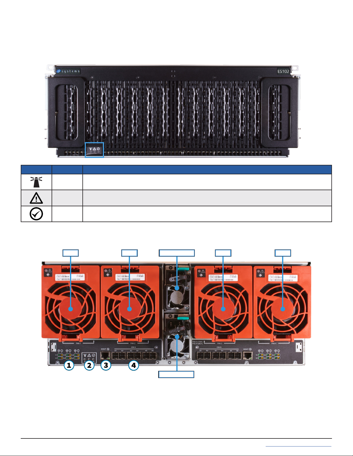
1.2 Become Familiar with the ES102
Indicators on the front panel show identication and status. The fault indicator is on during the initial power-on self-
test (POST) or when the TrueNAS software has issued an alert. These indicators are also on the back panel.
The ES102 has two expansion controllers in a side-by-side conguration.
Power Supply 1
Power Supply 2
Fan 1 Fan 2 Fan 3 Fan 4
1. SAS Connection Indicators (4)
2. Enclosure Indicators (see table above) (5)
3. Controller Management Port (not used) (6)
4. HD Mini SAS3 connectors (7)
LED Name Function
Identify Blinks Blue when identication is active or after identifying any component.
Fault Blinks Amber when Enclosure has a fault. O when Enclosure has no faults.
Power Solid Green when power is on.

2 Prerequisites
2.1 Safety
2.2 Tools
2.1.1 Static Discharge
2.1.2 Enclosure Size
There are additional considerations and some preparation required before installing the ES102 into a rack.
The ES102 is much larger than other Expansion Shelves sold by iXsystems. Be sure to take full safety precautions
when installing or servicing the enclosure.
You will need these tools to properly install the ES102 in a compatible rack:
Long T15 screwdriver and a #2 Philips head screwdriver.
You don’t need these items, but they can be useful when installing the ES102:
Tape measure, level, at head screwdriver, and cable ties.
The ES102 weighs 70 lbs unloaded and requires a minimum of two people to lift.
Do not attempt to lift the ES102 when it is fully populated with drives! The total weight of a fully-populated sys-
tem is over 260 lbs. When removing a fully-populated system from a rack, remove the drives before de-racking the
enclosure.
You will need at least 37.5” (952.5mm) empty space in front of a racked ES102 to fully extend the enclosure to ac-
cess all drive bays. Due to the weight of the enclosure, this can be a tipping hazard for the rack. Be sure to follow all
tipping prevention instructions recommended by your rack provider before installing the ES102.
Static electricity can build up in your body and discharge when touching conductive materials. Electrostatic
Discharge (ESD) is harmful to sensitive electronic devices and components. Keep these safety recommendations in
mind before opening the system case or handling non-hot-swappable system components:
1. Turn o the system and remove power cables before opening the case or touching internal components.
2. Place the system on a clean, hard work surface like a wooden tabletop. Using an ESD dissipative mat can also
help protect the internal components.
3. Touch the metal chassis with your bare hand to dissipate static electricity in your body before touching any
internal components, including components not yet installed in the system. Using an anti-static wristband and
grounding cable is another option.
4. Store all system components in anti-static bags.
You can nd more preventative tips and details about ESD at https://www.wikihow.com/Ground-Your-
self-to-Avoid-Destroying-a-Computer-with-Electrostatic-Discharge.

2.3 Rack Requirements
At minimum, the ES102 requires 4U of space in a EIA-310 compliant rack that is 47.24” (1200mm) deep, from frame
to frame. The vertical rack rails need to be spaced between 31.5” - 36.2” (800mm - 920mm) apart to properly install
the ES102 rails.
We recommend adjusting the front vertical rack rails to be as close to the front of the rack as possible to
prevent the cable management arms (CMAs) from protruding from the back of the rack.
The system with CMAs attached is 47.1 (1197mm) deep.
The rack must be a standard 17.72” - 18.31” (450mm - 465mm) wide, although a minimum 29.5” (750mm) cabinet
width allows for using a zeroU PDU with the enclosure. Narrower cabinets could require a rack-mounted PDU to
properly allow the enclosure to be fully installed into the rack and properly cabled with the included Cable Manage-
ment Arms.
For 52U racks, iXsystems recommends the AR3357X674. For a 42U rack, we recommend the AR3350 APC.
We recommend using the bottom-most available 4U space in the rack to better balance the system’s weight with
other equipment installed in that rack.
For both the AR3357X674 and AR3350 APC rack, we recommend using the STV-4501, STV-4502, or STV-4503 PDU.
3 ES102 Rail Installation Procedures
3.1 Enclosure Rails
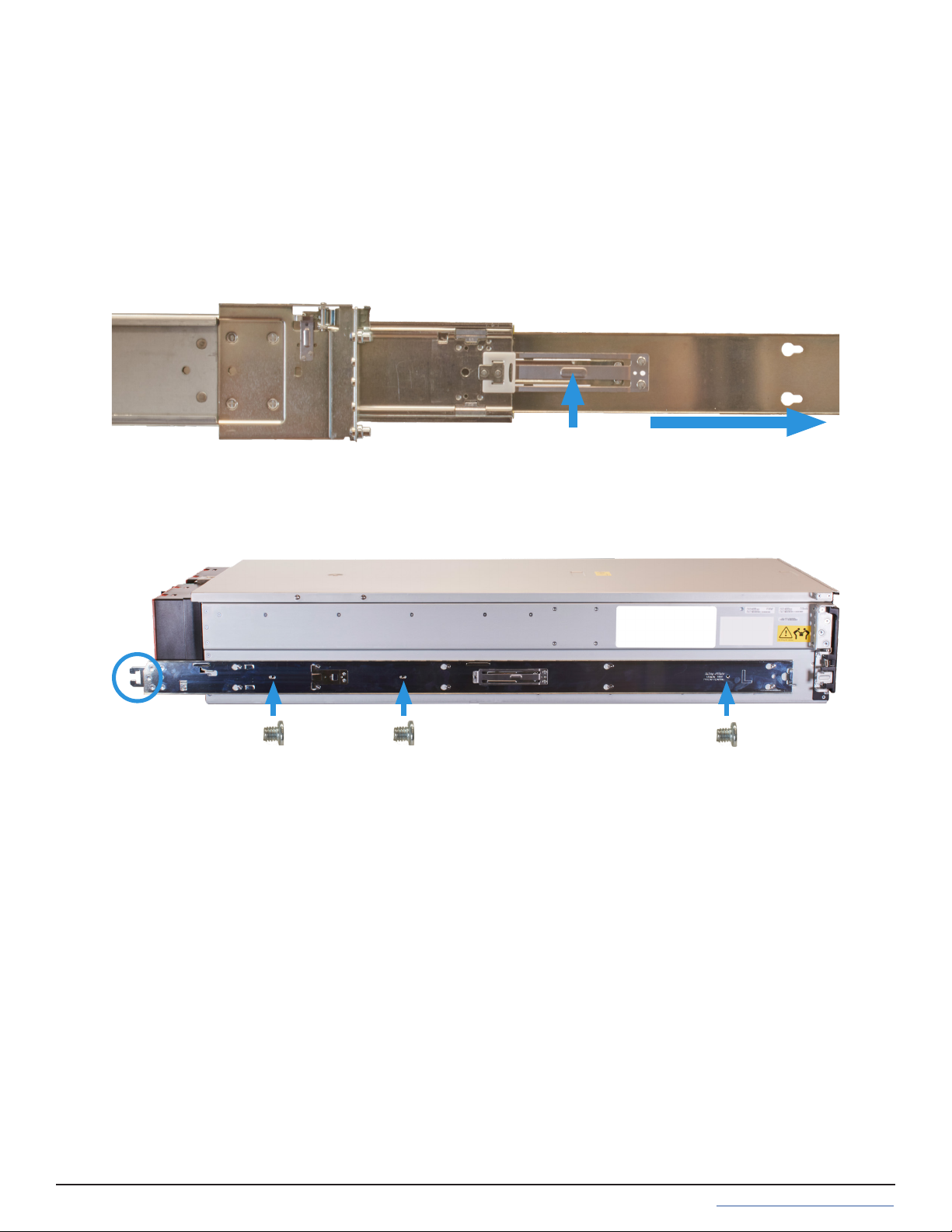
Each rack rail includes an inner chassis rail that must be removed. Extend the innermost rail as shown below until
it clicks into place and the metal safety catch is fully exposed. Push the safety catch in and continue to pull out the
innermost rail until it is completely free from the rack rail. Repeat the process for the second rail.
The chassis rails attach to each side of the ES102. Align the chassis rail keyholes with the ES102’s side posts. Slide
the rail towards the rear of the system until the metal tab clicks and locks the rail in place. Use three of the included
low-prole M4 Philips screws to secure the rail to the ES102. Repeat this process on the other side. The Cable Man-
agement Arm attach point will be at the back of the system.
ES102 rail installation has several steps. First, separate the chassis rails from the rack rails and install them on the
ES102. Then, t the rack rails inside the rack. Next, install the additional components to secure the ES102 drive cov-
er and latch the unit in the rack. Finally, you can reattach the ES102 to the rack rails and install it in the rack.
PRESS PULL
M4x3.2mm
(not to scale)
M4x3.2mm
(not to scale) M4x3.2mm
(not to scale)
The ES102 occupies 4U of rack space. The front rail pins mount to the 4U’s bottom-most attach points, and the back
rail pins mount to one space above the 4U’s bottom-most attach points. The rails are stamped for left side (L) and
right side (R) of the rack, according to your perspective when facing the rack.
Install the front of the rail rst. Align the rail pins with the mounting holes in the rack and push forward until the
front latch clicks into place on the rack. Make sure an additional 2U of rack space is available above the rail.
The rear of the rail can adjust to racks that have 32 -36 inches of space between the front and rear rack posts.
Align the rear rail pins with the rack’s mounting holes and push forward until the blue release catch clicks into place
over the rack. Note that the rear rail pins install one mounting hole higher than the front rail pins. You can use a level
to ensure the front and back of the rail are even.
3.2 Rack Rails
When installed correctly, the front and rear of the rail is level and the inner part of the rail with the gray bearing
sleeve is facing the inside of the rack. Use the same procedure to install the other rail, being sure to install both left
and right rails at the same height in each rack post.
Use three of the included washers and T15 M5 screws to secure the rear of the rail to the rack post.
Front Rear
T15 M5
Screws
Rear

4 Cover Retention
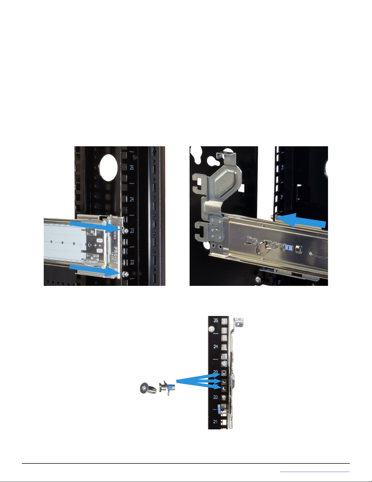
4.1 Attach Cage Nuts
4.2 Install Alignment Brackets
The cover retention components hold the cover in place when the unit slides forward out of the rack, simplifying
drive bay access. If you want cover retention, install alignment brackets over the rear of the rack rails. Then install
cage nuts at the system’s front for the cover retention screws.
You will need two of the included square cage nuts.
Take a cage nut and add it the topmost rack mounting hole of the required 4U of space. A at head screwdriver can
be helpful to push the cage nut “wings” into the rack mounting hole.
The nut should be inside the rack, with the attach “wings” touching the left and right sides of the hole (horizontal).
Repeat this process for the other rack post and make sure both cage nuts are installed parallel rack mounting holes.
Place the included Cover Alignment Bracket over the rail and align it with the mounting holes on the rear of the rack
rail. The groove in the bracket must be pointed toward the inside of the rack. Use ve washers and T15 M5 screws to
secure the bracket to the rear of the rack rail.
Use the same method to install the second alignment bracket to the other rail. Make sure the grooves on top of
both brackets point inside the rack. The ES102 cover slides into the grooves when it is pushed into the rack.
T15 M5
Screws
Rear
4U
Front

5 Latch Plates
The latch plates attach to the front of the rack rails. They secure the rails to the rack and hold the enclosure in place
when fully inserted in the rack. Align the plate over the three holds between the rack rail front mounting pins. The
ange must point to the outside of the rack. Use three T15 M5 screws to secure the latch plate, rack post, and rack
rails together.
Use the same procedure to install the second plate on the front of the other rail. Make sure that both anges on the
latch plates point to the outside of the rack.
Front
T15 M5 Screws
(not to scale)

6 Mount the Unit in the Rack
Caution: When using a lift, you need two people and 7ft of clearance between the system front and the rack. When
lifting unaided, you need three people and 5ft of clearance to safely lift and install the chassis. Do not install drives
until the chassis is installed in the rack. Remove all drives before removing the chassis from the rack.
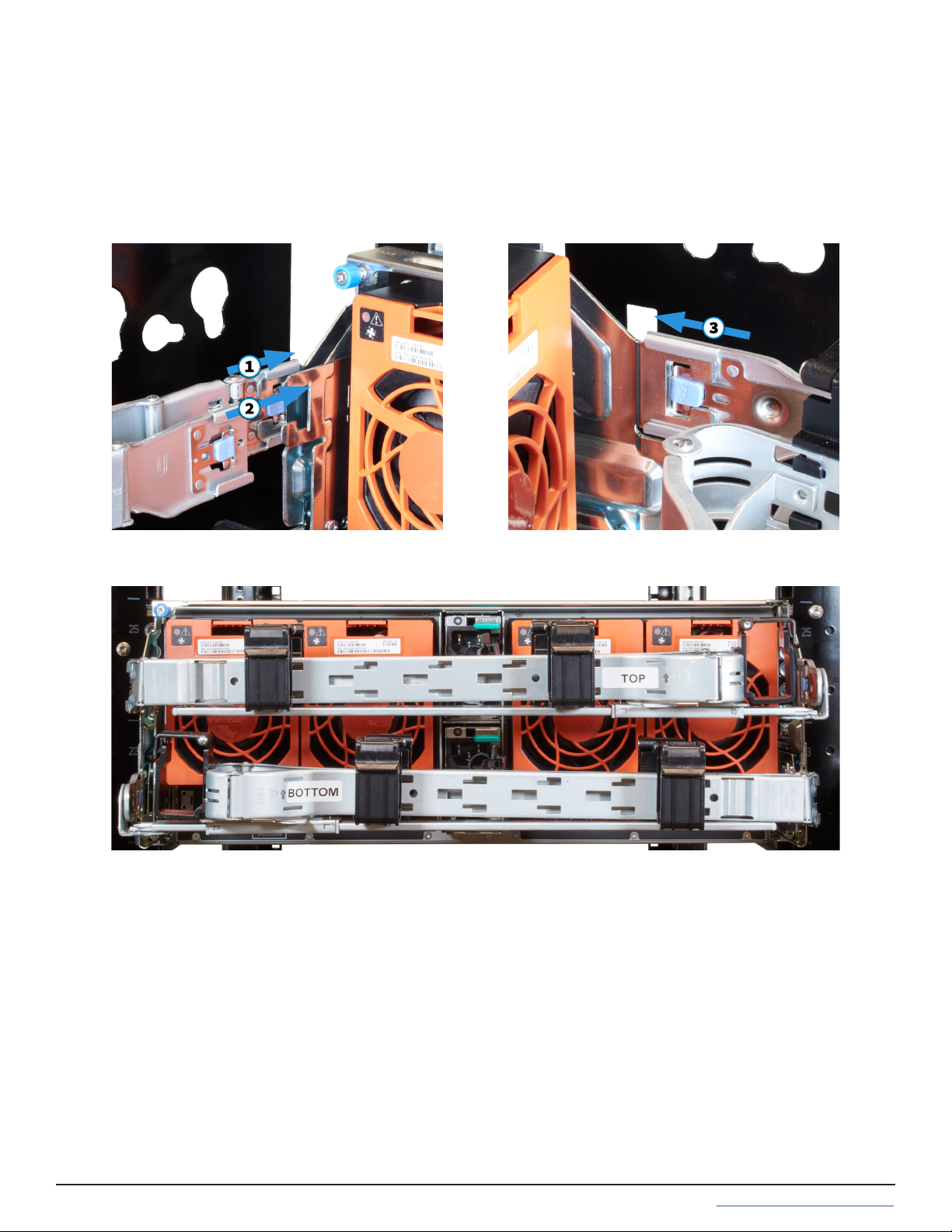
Slide the middle part of the rack rails out of the rack until they click into place (1). Make sure the inner bearing
sleeve is also slid as far forward as possible (2).
Caution: Do not use the front handles to lift the ES102! The handles are only for unlatching and sliding the enclo-
sure after attaching it to the rack rails. They cannot support the system’s weight. Lift the ES102, align the attached
cabinet rails with the middle rack rails, and push the ES102 into the rack rails until it stops.
Locate the metal safety catches on each chassis rail and squeeze them into the chassis (1). Hold the safety catches
in place and push the chassis into the rack (2) until the chassis latches touch the rail latch plates.
Make sure the enclosure cover slides into the Alignment Bracket grooves at the rear of the rack.
To minimize any jarring motions, softly secure the enclosure in place by swinging the front handles out (1) and
gently pushing the enclosure forward until it is fully in the rack (2). After releasing the handles, the enclosure latches
catch behind the latch plates and hold the system in the rack (3).

6.1 Attach Cover Retention Screws
To hold the ES102 cover in place when the system is slid out of the rack, attach the two included Philips head reten-
tion screws through the left and right cover retention holes and into the installed cage nuts. Make sure both screws
are tight enough to securely hold the cover in place.
Cover Retention Screw
(not to scale)
6.2 Shipping Screws
If you will be installing the ES102 in a rack for shipping purposes, install four more M5 cage nuts in holes 3-6 of the
4U space. These will receive the M5 x 12mm T15 Flat Head Torx screws that secure the enclosure to the rack with
the shipping bracket.
4U
Space M5 x 12mm T15
Flat Head Torx screws
x4
(not to scale)

7 ES102 Cable Management Arms
You need the included Cable Management Arms (CMA) to ensure the ES102 remains properly cabled while sliding
out of the rack. There are two CMAs included with the ES102 that attach to the rear of the enclosure in an Upper (U)
Lower (L) conguration. The CMAs include a brace that stabilizes the CMAs and rails together.
7.2 Install Lower Cable Management Arm
There are three attach points for the lower CMA, two on the right rail and one on the left. Beginning with the right
side, insert the outermost connection post into the outer bracket until it clicks into place (1). Now, align and insert
the inner post into the innermost bracket (2). Swing the back of the CMA to the left rail and insert the post into the
left bracket until it clicks into place (3).
7.1 Attach Cable Management Brace
At the back of the system, insert the brace pivot pin into the top bracket on the right rail (1). Align the brace with the
top bracket on the left rail (2) and tighten the thumbscrew until the brace is rmly in place (3).
You will need the CMA stamped Lower (L) for this procedure.
7.3 Install Upper Cable Management Arm
You will need the CMA stamped Upper (U) for this procedure.
There are three attach points for the upper CMA, two on the left rail and one on the right. Beginning with the left
side, insert the outermost connection power into the outer bracket until it clicks into place (1). Now align and insert
the inner post into the innermost bracket (2). Swing the back of the CMA to the right rail and insert the post into the
right backet until it clicks into place (3).
Before installing any drives in the ES102 or routing any cables through the CMAs, test the installation by unlatching
the enclosure and sliding it forward until it clicks into place. The CMAs will fully extend behind the ES102, and the
cover will remain in place, exposing the drive and component bay.
If you feel any grinding or the enclosure unexpectedly stops before locking into place, don’t force the motion! Care-
fully press the enclosure rail safety catches and push it back into the rack. Secure it in place, and verify the Cable
Management Arms, Latch Plates, Cover Alignment Brackets, and Rails are correctly installed.
Here is how the back of the system should appear with both CMAs properly installed:
8 Drive Installation
Do not install the drives until the enclosure has been installed in the rack. Only approved WD drives are
compatible with the ES102.
The ES102 ships with all the drives needed to fully populate the enclosure, packaged separately. Drives ship already
attached to the drive clips, but in the event you need to replace a failed drive, the clip attach procedure is below.
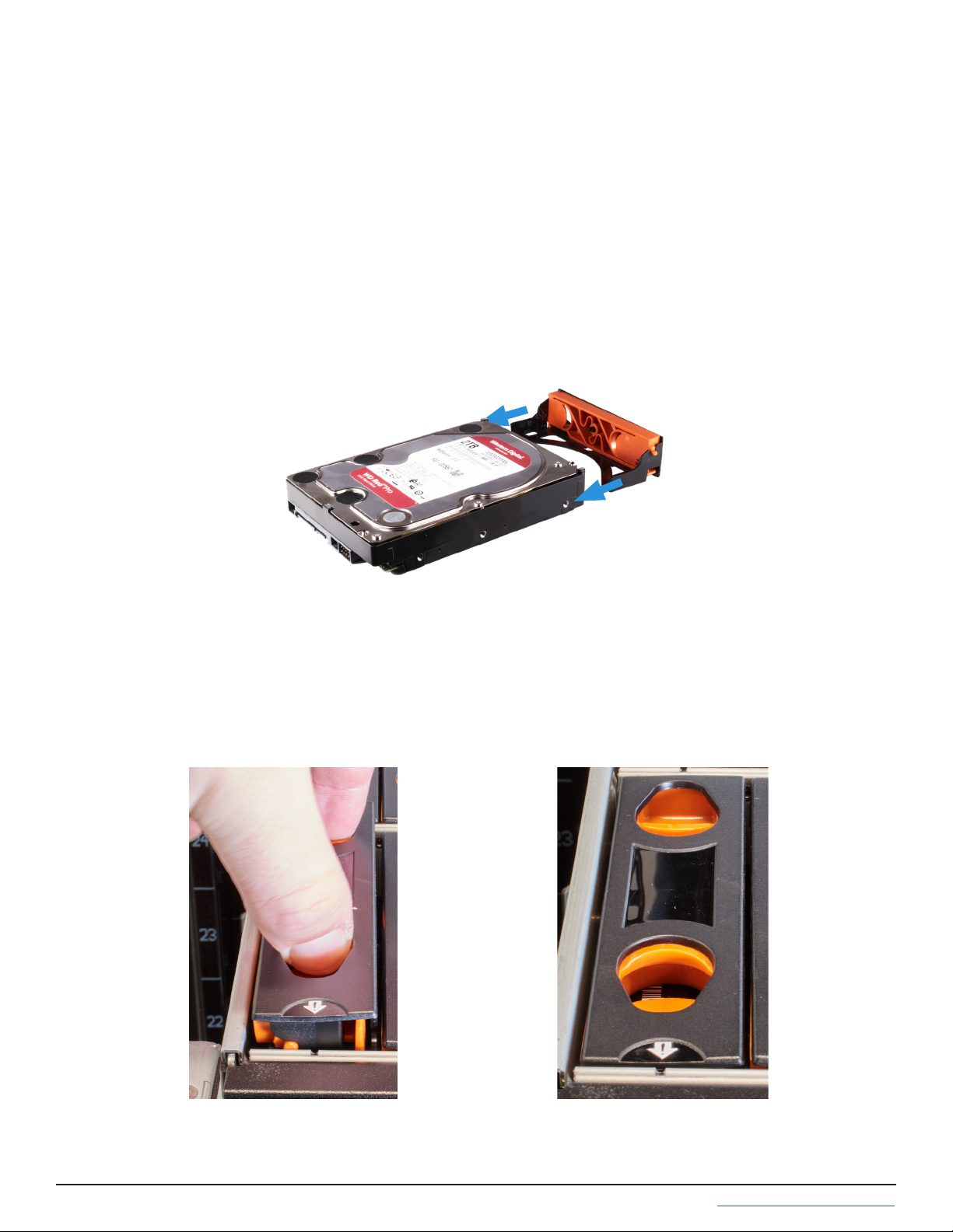
8.1 Attach Clip to Drive
8.2 Insert Drives into the Enclosure
Use drives with attached clips to install drives into the enclosure from back to front.
To install a drive, point the arrow on the clip towards the enclosure’s front. Pinch the orange clips and gently push
the drive down into the enclosure slot. Release the orange clips to secure the drive in place. Ensure the drive is fully
inserted into the enclosure and does not extend above the system. You might need to gently work the clip into the
sides of the bay to secure it in place.
ES102 drive clips t over the front of a drive and have two plastic pegs that pop into the frontmost screw holes on
the left and right sides of the drive.
Align the drive and clip so the the bottom of the clip ts over the bottom of the drive and the drive connection ports
are on the opposite end from the clip. Push the clip connection peg into place on one side of the drive and then
gently ex the clip over the drive until the other connection peg pops into place.
For proper airow, be sure to follow this drive installation order:
Starting with the row at the back of the ES102 drive bay, install the drives from left to right. When that row is full,
move to the next row forward and proceed to ll the enclosure from left to right, back to front.

8.3 Drive LED Indicators
There is a single amber LED on each drive bay. The LED indicates dierent drive states:
• Drive Insertion: Amber Light - Solid Note: LED stays in this state until the shelf is closed
• Normal Behavior: No light.
• Activity: No light.
• Issue/Fault: Amber Light - On for one second, then o (repeats).
• Identify: Amber Light - On for two seconds, then o (repeats). The front chassis blue identify light also blinks.
• Hot-Spare: No light

9 Cabling
The ES102 only accepts 200-240v power input. Connect a power cord to the back of one power supply. Extend
the plastic retention clamp, open it, t it over the power cable, and push it down over the cable to lock it in place.
Repeat the process to connect the second power supply and secure the cord.
9.1 Power Cables
Do not plug the power cords into a power outlet yet.
Start by connecting cables to the various ports on the back of the ES102 and routing through the cable management
arms. Make sure to leave enough ex in the cables so that they don’t pull out of place when the enclosure slides out
of the rack.
Service and Management ports are not used during normal operation and do not require cabling.
9.2 SAS Cables
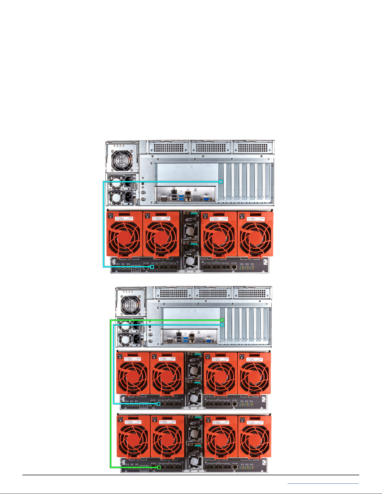
ES102 systems are compatible with the M60 and R50 Unied Storage Arrays. Typical SAS cable connections for two
ES102s to either system are shown here.
R50 with a single ES102 Expansion Shelf:
R50 with two ES102 Expansion Shelves:
9.2.1 R50
To set up SAS between your TrueNAS system and Expansion Shelves, cable the rst port on the rst TrueNAS
Controller to the rst port on the rst Expansion Shelf Controller. High Availability systems require another cable
from the rst port on the second TrueNAS Controller to the rst port on the second Expansion Shelf Controller.
We DO NOT recommend other cabling congurations. Contact iX Support if you need other cabling methods.
Warning: When setting up your SAS connections, please adhere to the wiring examples in this guide.
Connecting expansion shelves incorrectly will cause errors. Never cable a single controller to dierent
expanders on the same expansion shelf.


If the TrueNAS system is already on, you can turn on the ES102 any time by plugging both power cords into PDU
outlets and waiting two minutes for the drives to start.
9.3 Cable Routing
To simplify cabling with the Cable Management Arms (CMAs), swing open both arms so that they point directly away
from the enclosure. To do this, start with the lower arm and press the blue release catch on the left side connector,
then swing the arm to the right. Release the right side connector on the upper arm and swing it to the left.
To open the cable retention clips, gently squeeze and lift the top of the clip.
To ensure there is enough ex in the cables to allow sliding the enclosure fully out of the rack, we recommend
routing cables for the rst Storage Controller (left side) through the lower CMA (right side) (1). Route cables for the
second Storage Controller (right side) through the upper CMA (left side) (2). Allow plenty of ex in the cables by not
pulling them tightly through the CMAs.
When nished routing cables through the CMAs, close all the cable retention clips and swing the arms closed,
reconnecting each side to the enclosure. If you see any cables getting pinched or pulled while closing the arms, do
not force the motion! Return to the starting position and adjust the cables to allow more ex or avoid pinching.
Other manuals for ES102
2
Table of contents
Other TrueNAS Storage manuals

TrueNAS
TrueNAS Mini X+ Installation and operation manual

TrueNAS
TrueNAS ES60 Manual

TrueNAS
TrueNAS R Series Manual

TrueNAS
TrueNAS M Series Manual

TrueNAS
TrueNAS ES60 Manual

TrueNAS
TrueNAS R Series User manual

TrueNAS
TrueNAS ES24 Manual

TrueNAS
TrueNAS ES60 Manual

TrueNAS
TrueNAS M Series Manual

TrueNAS
TrueNAS M Series Manual


Popular Storage manuals by other brands

StarTech.com
StarTech.com IDECASE25U2 InfoSafe instruction manual

Addonics Technologies
Addonics Technologies AD25CFASTD user guide

Glyph
Glyph GT103800-1000 Specifications

Nexsan
Nexsan BEAST BT60 installation guide

HP
HP StorageWorks Ultrium 230 User's and service guide

Hama
Hama Valeus FlashPen Operating instruction


