CellarPro 3000Scm User manual

V3.3.16
Control the Elements
Split Ceiling Mount
Refrigeration Systems
Owner’s Manual

V3.3.16
C O N G R A T U L A T I O N S !
Thank you for purchasing a new CellarPro cooling system.
Please take a minute to read through this Owner’s Manual before you unpack,
install and turn on your Cooling Unit.
If you have any questions about your new cooling unit, it is likely that you will find the
answers in this Owner’s Manual. We also have more information on our website,
including the latest version of the Owner’s Manual, at www.cellarpro.com/customer-
service .
If you still have questions, please don’t hesitate to contact your dealer or CellarPro
directly. We can be reached during normal business hours at 707.794.8000. You also
Contact Information:
CellarPro Cooling Systems
1445 N. McDowell Blvd
Petaluma, CA 94954
707.794.8000
Email: info@cellarprocoolingsystems.com
Website: www.cellarprocoolingsystems.com
IMPORTANT WARRANTY INFORMATION FOR YOUR SPLIT SYSTEM
Make sure to activate your warranty by having the installing technician complete
the Support and Data Service Sheet at the end of this Owner’s Manual.Once
completed, please fax to us at 707.794.8005, or scan and email to us at
Once we receive the completed Sheet, we'll review the data to make sure the cooling
system is installed properly.
YOUR WARRANTY WILL NOT BE ACTIVATED UNTIL WE RECEIVE THE
COMPLETED CHECKLIST AND INSTALLATION ISSUES (IF ANY) HAVE BEEN
RESOLVED. If the unit malfunctions, we cannot assist you unless/until we receive the
completed checklist. If the unit is damaged because of improper installation, repair
services will be provided on a time and materials basis.

3 V3.3.16
Table of Contents
I. Package Contents 4
II. Specifications, Cut Sheets, and Cellar Construction 5
III. Installation Instructions 10
IV. Operating Instructions 43
V. Troubleshooting 47
VI. Limited Warranty 52
VII. Warranty Activation Checklist 53

4 V3.3.16
I. Package Contents
3000Scm/4000Scm
BOX 1: BOX 2:
DESCRIPTION QTY DESCRIPTION QTY
EVAPORATOR 1CONDENSING UNIT 1
CEILING MOUNT BOLT 4
FENDER WASHER 8BOX3 (OPTIONAL):
FLANGE NUT 4DESCRIPTION QTY
DRAIN TUBING 25 FT.
CONDENSING UNIT OUTDOOR
COVER
1 SET
OWNERS MANUAL 1
COVER ASSEMBLY
HARDWARE
1 SET
REMOTE DISPLAY KIT 1
REMOTE DISPLAY
LEADWIRE
10 FT.
SIGHTGLASS 1
FILTER DRIER 1
6000Scm/8000Scm
BOX 1: BOX 3:
DESCRIPTION QTY DESCRIPTION QTY
PRIMARY EVAPORATOR 1CONDENSING UNIT
CEILING MOUNT BOLT 8
FENDER WASHER 16 BOX4 (OPTIONAL):
FLANGE NUT 8DESCRIPTION QTY
DRAIN TUBING 25 FT.
CONDENSING UNIT OUTDOOR
COVER
1 SET
OWNERS MANUAL 1
COVER ASSEMBLY
HARDWARE
1 SET
REMOTE DISPLAY KIT 1
REMOTE DISPLAY
LEADWIRE
10 FT.
SIGHTGLASS 1
FILTER DRIER 1
BOX 2:
DESCRIPTION QTY
SECONDARY
EVAPORATOR
1
DRAIN TUBING 25 FT.

5 V3.3.16
II. Specifications, Cut Sheets and Cellar Construction
Evaporator
Model
Dimensions
W x D x H (inches)
Weight
(lbs.)
Running Amps
(with fan on “high”)
3000Scm 35.1 x 18.8 x 6.5 55 7.0
4000Scm 35.1 x 18.8 x 6.5 55 9.3
6000Scm (2) @ 35.1 x 18.8 x 6.5 110 14.7
8000Scm (2) @ 35.1 x 18.8 x 6.5 110 16.3
Condensing unit - Indoor
Condensing unit - Outdoor
Model
Dimensions
W x D x H (inches)
Weight
(lbs.)
Dimensions
W x D x H (inches)
Weight
(lbs.)
3000Scm 13.5 x 18.9 x 9.1 42
19.4 x 23.3 x 18.8
(with cover)
73
4000Scm 13.5 x 18.9 x 10.3 45 76
6000Scm 13.9 x 18.9 x 11.9 54 85
8000Scm 16.8 x 20.8 x 14 76 107

6 V3.3.16
Evaporator Cut Sheets

7 V3.3.16
Condensing Unit Cut Sheets

8 V3.3.16
Insulation
CellarPro cooling units are designed to be installed inside wine cellars that have
proper insulation, moisture barriers and an airtight seal from the environment outside
the cellar. Interior walls and floor should have a minimum of R-11 insulation, and
avaporbarrier on the warm side
of the insulation. The ceiling
should have a minimum of R-
19 insulation and a vapor barrier
on the warm side of the
insulation. Doors also should
be insulated and tightly
sealed with weather
stripping around the
perimeter of the door.
Surface-mounted fixtures are
recommended over
recessed lighting, which can
allow air to leak into the
cellar.
It is important that all walls,
joints, doors and windows,
electrical outlets and/or switches, pipes, vents and light fixtures be sealed to prevent
air and moisture from entering the cellar. If there is a leak in the cellar, the cooling unit
will build up excess condensation.
The condensate pump drain line must be routed to an appropriate water drain.
Fan Speeds
Your fan speed setting will depend on the thermal load on the wine cellar, and the
resulting BTU that is required to cool and maintain your wine cellar at the desired
temperature.
Ventilation
Adequate ventilation is critically important for the proper operation of your CellarPro
cooling unit.

9 V3.3.16
Outside the Cellar
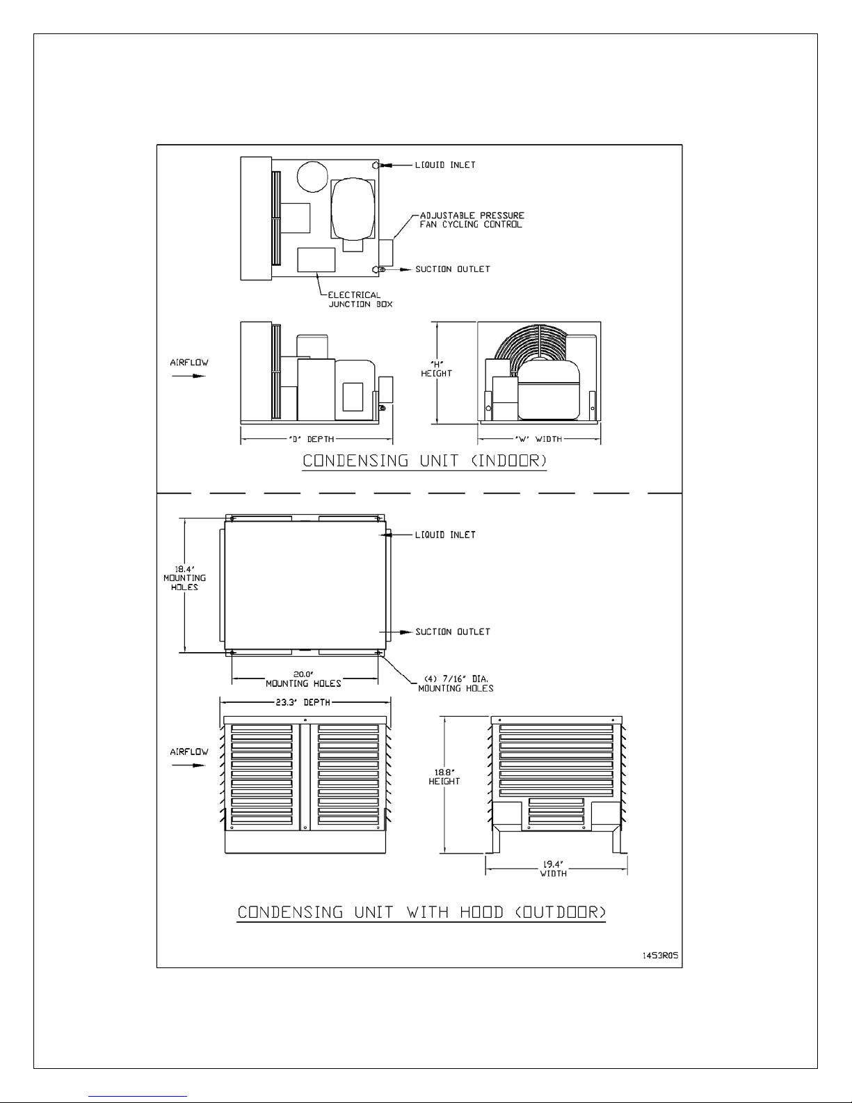
Condensing unit Air Exhaust. Condensing units create significant hot air which
must be exhausted into an appropriately-sized space in order for the heat to
dissipate. If the space is constrained and/or too small, the heat will not dissipate. In
this event, the cooling unit will be forced to re-circulate its hot air exhaust and/or the
static pressure will back up the cooling unit. If this happens, the cooling unit’s ability
to create cold air inside the cellar will be compromised.
Condenser Air Intake. The condenser coils require access to cool air in order for
the cooling unit to produce cold air. In addition, the cooling unit must be installed so
that, after its installation, the condenser coils are accessible for periodic cleaning.
The Condensing unit cannot be ducted.
Inside the Cellar
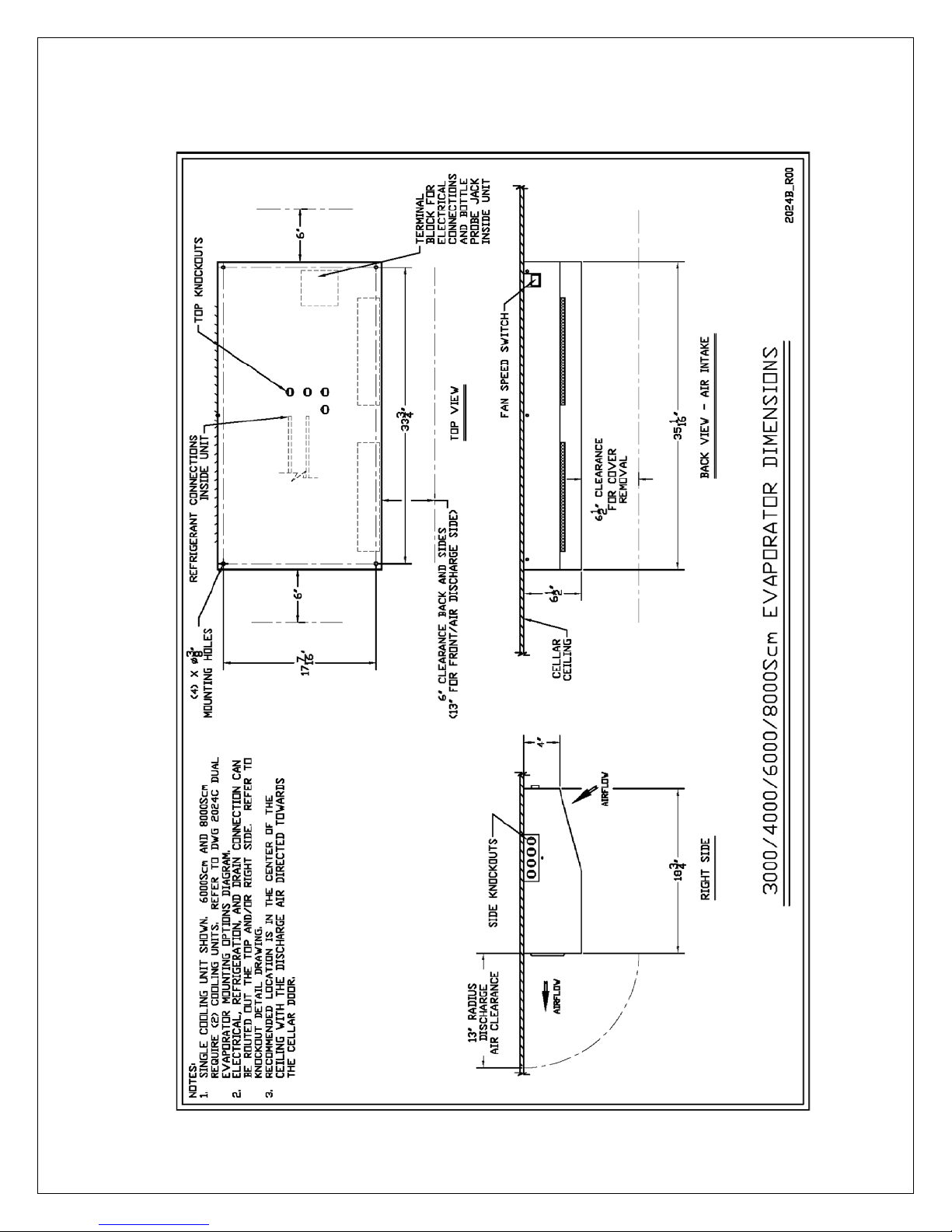
Evaporator Air Intake
.
When the warm air passes across the evaporator coils, heat
is removed fromthe air, and the resulting cold air is exhausted into the cellar. To ensure
proper airflow, minimum clearance of 6” is required at the air intake of the cooling unit
(refer to Evaporator Cut Sheet).
Evaporator Air Exhaust.
Cold air is exhausted at the front of the cooling unit. Because
CellarPro cooling units are located at the highest point inside wine cellars, the cold air
exhaust eventually will drop to the bottom of the cellar. To ensure proper airflow and
reduce temperature stratification inside the cellar, the space in front of the cold air
discharge should be clear of any obstructions, including wine bottles, wine racks, etc. A
minimum clearance of 13” is required at the air exhaust (refer to Evaporator Cut Sheet).
We also offer a bottle probe (10 foot cord) that can be plugged into the cooling unit,
as well as 25’ and 50’ extension cords. The probe jack is located inside the ceiling
mounted housing.

10
V3.3.16
III. Installation Instructions
Installation Instructions
Split System piping and wiring must be installed by a qualified Refrigeration
Technician in accordance with local and national code requirements.
Condensing Unit Installation
Indoor and Outdoor Units
The unit is designed to operate in temperatures ranging from 0°F to 110°F. A
compressor heater (sold separately) is required for temperatures below 40°F.
Indoor Units
Condensing units can be installed remotely from the cellar in an area protected
from direct exposure to moisture and sunlight.
The area must have suitable ventilation to maintain an ambient temperature of
110°F or less.
If the area does not have adequate ventilation, a vent fan should be added to
supply fresh air to the space (suggested 600CFM).
A minimum of 12" of open air space is required in front of the condenser coils.
Indoor units can be installed with the optional outdoor hood if additional mechanical
protection is desired.
A minimum of 12" of open air space around the perimeter of the outdoor hood is
required.
Outdoor Units
Condensing units must be installed with the outdoor hood if the unit will be located
outdoors.
A minimum of 12" of open air space around the perimeter of the outdoor hood is
required.
Evaporator Unit Installation
As warm air rises to the top of the cellar, the cooling unit pushes the warm air through
the evaporator coil and removes the heat from the warm air. Once cooled, the cold air
is discharged from the front of the cooling unit and circulates through the cellar.
Therefore, we recommend mounting the evaporator in the center of the cellar
ceiling, with the evaporator air exhaust directed toward the cellar door.

11
V3.3.16
Evaporator Mounting Detail

12
V3.3.16
Dual Evaporator Mounting Options
6000Scm and 8000Scm models require two evaporators to be mounted in the cellar.
These may be mounted in either of the two orientation options shown in the drawing
below.

13
V3.3.16
Knockout Detail
For greater flexibility, 7/8” knockouts are available in the top panel for connections to pass
through the cellar ceiling, and in the right side panel for connections running along the
interior cellar ceiling. The type of connection by knockout location is illustrated on the
following Knockout Detail drawing:

14
V3.3.16
Condensate Drain Line
Each evaporator has an internal integrated condensate pump with 25 feet of ¼”
PVC drain tubing. This tubing should be routed to a suitable drain according to
the following design limits:

15
V3.3.16
Condensate Pump Operation Test
When the system is ready to start up, test the condensate pump before installing the
evaporator cover by powering up the system and submerging the pump in a tray filled
with water to verify the pump operates and discharges water to the final drain.
The condensate pump is self-priming. The pump activates when the water level in
the evaporator cover reaches a depth of 5/8”, and shuts off when the water level
reaches 3/16”. The pump will activate an overflow alarm at a level of 1”, indicated by
“CA” on the temperature controller display. The refrigeration is disabled while this
alarm condition persists, but the pump will continue to run until the alarm is cleared.
Over time, the pump sensor may become contaminated by particles in the
condensate water causing the pump to run constantly. If this occurs, flush the sensor
with clean water through the pump sensor housing vents.

16
V3.3.16
OPTION A: DUAL POWER VALVE CONTROL WIRING OPTION
SEPARATE POWER SUPPLIES FOR EVAPORATOR AND CONDENSING UNIT
EVAPORATOR CONDENSING UNIT
SPLIT
SYSTEM
EVAP EVAP
FAN RATINGS @
115V/1Ph/60Hz
POWER INPUT
WATTS
UNIT AMPS @
115V/1Ph/60Hz
POWER
INPUT
MODEL MCA MOP
Fan
Amps
HIGH LOW HIGH LOW MCA LRA MOP WATTS
3000Scm 2.31 15 1.85 1.9 1.0 143 104 6.33 28.2 15 442
4000Scm 2.31 15 1.85 1.9 1.0 143 104 9.20 40.0 15 591
6000Scm 4.16 15 3.70 3.7 2.0 286 208 13.50 53.0 20 922
8000Scm 4.16 15 3.70 3.7 2.0 286 208 15.35 51.0 25 1028
NOTES:
SYSTEM POWER SUPPLY
115V/1Ph/60Hz
EVAPORATOR
CONDENSING
UNIT
SPLIT
SYSTEM
System System
POWER INPUT
WATTS
Evap
Fan
Fan Speed Comp
Comp
MODEL MCA MOP HIGH LOW Amps HIGH LOW LRA RLA
3000Scm 8.18 15 585 546 1.85 1.9 1.0 28.2 4.70
4000Scm 11.05 15 734 695 1.85 1.9 1.0 40.0 7.00
6000Scm 17.20 25 1208 1130 3.70 3.7 2.0 53.0 10.00
8000Scm 19.05 25 1314 1236 3.70 3.7 2.0 51.0 11.20
NOTES:
1) A 15 amp dedicated circuit breaker (non GFI) is recommended for 3000-4000S,Sh,Scm systems.
3) A 25 amp dedicated circuit breaker (non GFI) is recommended for 6000-8000S,Sh,Scm systems.
2) 6000Scm and 8000Scm systems are configured with dual evaporators, wired Primary and Secondary. Main
power supply connection is to the Primary Unit, with interconnect wiring to the Secondary Unit.
OPTION B: SINGLE POWER ELECTRONIC CONTROL WIRING OPTION
SINGLE POWER SUPPLY TO EVAPORATOR (CONDENSING UNIT POWERED
2) 6000Scm and 8000Scm systems are configured with dual evaporators, wired Primary and Secondary. Main
power supply connection is to the Primary Unit, with interconnect wiring to the Secondary Unit and Condensing
Unit.
1) Separate 115V / 1Ph / 60Hz power supplies are required for the Evaporator and the Condensing Unit.
3) A 15 amp circuit breaker is recommended for all Evaporator models.
4) A 15 amp dedicated circuit breaker (non GFI) is recommended for 3000-4000S,Sh,Scm Condensing Units.
5) A 20 amp dedicated circuit breaker (non GFI) is recommended for the 6000S,Scm Condensing Unit.
6) A 25 amp dedicated circuit breaker (non GFI) is recommended for the 8000S,Scm Condensing Unit.

17 V3.3.16
3000/4000Scm System Wiring – Option A: Dual Power / Valve Control
Under this configuration the Evaporator and Condensing units are separately
powered, and the Condensing unit turns on and off based on suction pressure, as
follows:
•The Evaporator includes a factory installed liquid line solenoid valve (LLSV),
which is controlled by the Evaporator temperature controller. The Condensing
unit is controlled by a low pressure switch which reacts to the suction pressure
and senses whether the LLSV is open or closed.
•When the Evaporator temperature set-point is reached and the Evaporator turns
off, the LLSV closes, causing the system to pump down until the low pressure
switch shuts off the Condensing unit.
•When the Evaporator turns on, the LLSV opens, causing the suction pressure to
rise and activate the Condensing unit.
Field power wiring is connected to both the Evaporator and Condensing units, no
interconnecting wiring is needed between the Evaporator and Condensing unit.
Evaporator Field Power Wiring:
Connect line lead to Evaporator terminal "L"
Connect neutral lead to Evaporator terminal "N"
Connect power ground to grounding lug on Evaporator
Condensing Unit Field Power Wiring:
Connect line lead to Condensing unit terminal "L1"
Connect neutral lead to Condensing unit terminal "L2"
Connect power ground to grounding lug on Condensing unit.

18
V3.3.16

19
V3.3.16
6000/8000Scm System Wiring – Option A: Dual Power / Valve Control
Under this configuration the Primary Evaporator and Condensing units are separately
powered, the Secondary Evaporator is powered from the Primary Evaporator, and the
Condensing unit turns on and off based on suction pressure, as follows:
•Both the Primary and Secondary Evaporators include a factory installed liquid line
solenoid valve (LLSV), which is controlled by the Evaporator temperature controller
in the Primary Evaporator. The Condensing unit is controlled by a low pressure
switch which reacts to the suction pressure and senses whether the LLSV is open
or closed.
•When the controller temperature set-point is reached, both of the LLSV close,
causing the system to pump down until the low pressure switch shuts off the
Condensing unit.
•When the controller calls for cooling, both of the LLSV open, causing the suction
pressure to rise and activate the Condensing unit.
Field power wiring is connected to the Primary Evaporator and Condensing units, and
interconnect wiring between the Primary and Secondary Evaporators. No
interconnecting wiring is needed between the Evaporator and Condensing unit.
Primary Evaporator Field Power Wiring:
Connect line lead to Primary Evaporator terminal "L"
Connect neutral lead to Primary Evaporator terminal "N"
Connect power ground to grounding lug on Primary Evaporator
Secondary Evaporator Field Interconnect Wiring from Primary Evaporator:
Interconnect power leads to terminals “18”, “20”, “22”, and “26”
Interconnect 18/2 thermostat wiring to terminals “8” and “9”
Connect power ground to grounding lug on Secondary Evaporator
Condensing Unit Field Power Wiring:
Connect line lead to Condensing unit terminal "L1"
Connect neutral lead to Condensing unit terminal "L2"
Connect power ground to grounding lug on Condensing unit.

20
V3.3.16
This manual suits for next models
3
Table of contents
Other CellarPro Freezer manuals