Celli Brave 30 ES User manual

30/10/2017
ED. 10
Celli S.p.A.
Via Casino Albini, 605
47842 - S. Giovanni in Marignano - Rimini - Italy
Tel. +39 0541 755211 - Fax +39 0541 759735
www.celli.com - [email protected]
Code 070344
TRANSLATION OF THE ORIGINAL
BRAVE 30 ESBRAVE 30 ES
BRAVE 90 ESBRAVE 90 ES
BRAVE 60 ESBRAVE 60 ES
USE
USE
AND
AND
MAINTENANCE MANUAL
MAINTENANCE MANUAL
USE
USE
AND
AND
MAINTENANCE MANUAL
MAINTENANCE MANUAL


Index
1
Brave 30 ES - Brave 60 ES- Brave 90 ES
Index
1 - Safety .....................................................................................................................3
1.1 Intended use ..................................................................................................................... 3
1.2 Improper use .................................................................................................................... 3
1.3 List of hazards ................................................................................................................... 4
1.4 Residual risks .................................................................................................................... 6
2 - General information ............................................................................................... 7
2.1 Manufacturer’s details ........................................................................................................ 7
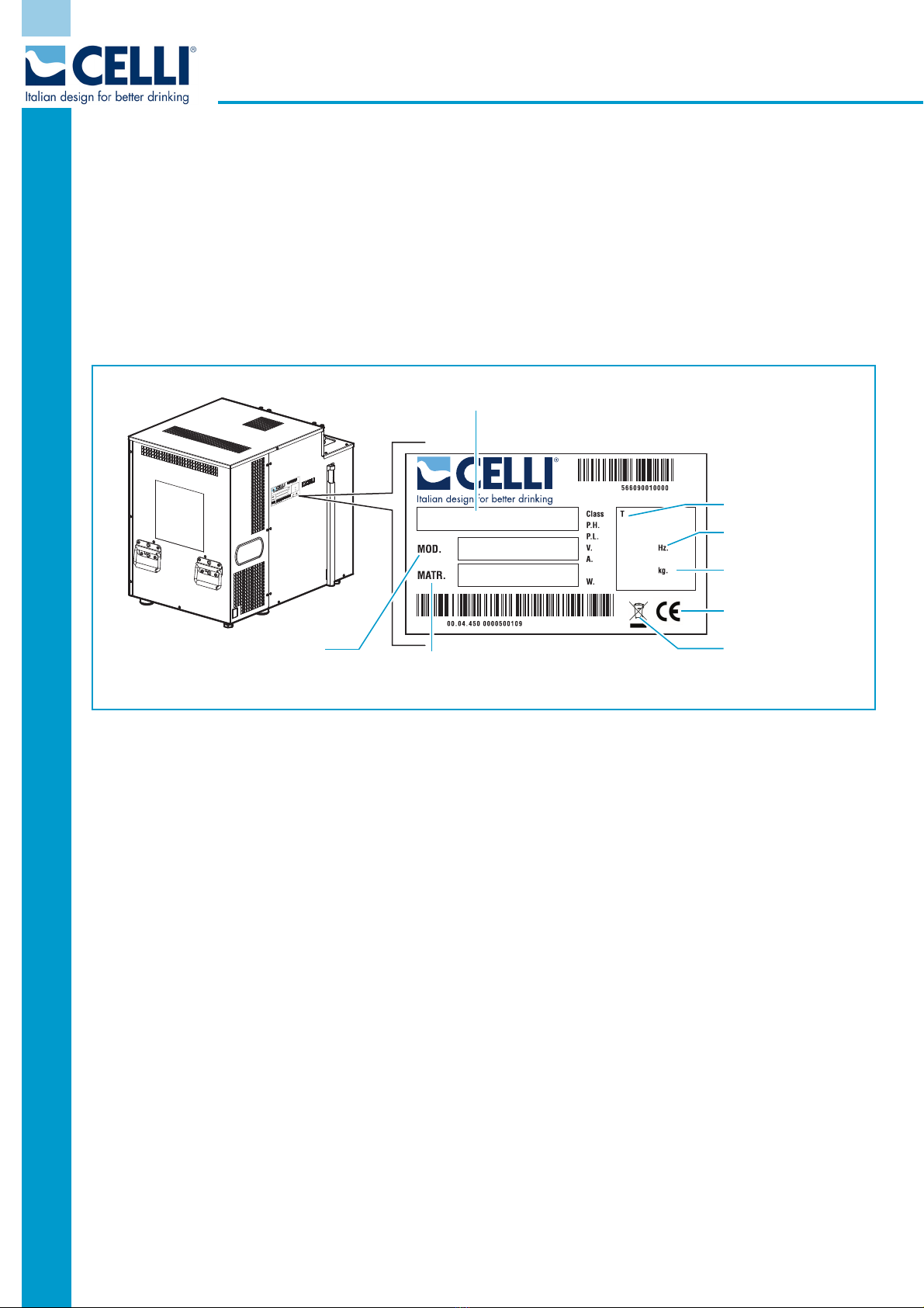
2.2 Machinery identification...................................................................................................... 8
2.3 Warranty........................................................................................................................... 8
2.4 Symbols used in the manual ............................................................................................... 9
2.5 Staff qualification............................................................................................................... 9
3 - Description of the machine ..................................................................................10
3.1 Main components of the BRAVE 30 ES................................................................................11
3.2 Main components of the BRAVE 60 ES................................................................................13
3.3 Main components of the BRAVE 90 ES................................................................................15
3.4 Operating principle............................................................................................................17
3.5 Energy Saving control unit, and button pad with display ......................................................20
3.5.1 Standard functions ...................................................................................................21
3.5.2 Optional functions ....................................................................................................22
3.6 Technical data ..................................................................................................................25
3.6.1 Sound emissions ......................................................................................................25
3.7 Dimensions in mm ............................................................................................................26
3.7.1 BRAVE 30 ES............................................................................................................26
3.7.2 BRAVE 60 ES............................................................................................................26
3.7.3 BRAVE 90 ES............................................................................................................26
3.8 Differential-switch power cord (optional) ............................................................................27
4 - Installation ........................................................................................................... 28
4.1 Checks and Unpacking ......................................................................................................28
4.2 Positioning .......................................................................................................................28
4.3 Environmental conditions...................................................................................................29
4.4 Electrical requisites ...........................................................................................................29
4.5 Connections .....................................................................................................................30
4.5.1 Preparing the machine..............................................................................................30
4.5.2 Water intake connection ...........................................................................................31
4.5.3 Connecting the syrup lines ........................................................................................33
4.5.4 Connecting the soda recirculation line ........................................................................33
4.5.5 Connecting the python..............................................................................................34
4.5.6 Carbon dioxide (CO2) connection ...............................................................................35
4.5.7 Electrical connection .................................................................................................37
4.6 Adjusting the carbon dioxide (CO2) supply..........................................................................38
4.7 Checking for leaks.............................................................................................................39
4.8 Adjusting the dispensing valves .........................................................................................39
4.9 First start-up ....................................................................................................................41

Index
2
Rev. 10/17
Brave 30 ES - Brave 60 ES - Brave 90 ES
5 - Using the machine ............................................................................................... 42
5.1 Start-up........................................................................................................................... 42
5.2 Stopping the machine ....................................................................................................... 42
6 - Maintenance......................................................................................................... 43
6.1 Routine maintenance........................................................................................................ 43
6.2 Table of procedures.......................................................................................................... 44
6.3 Replacing the syrup tank................................................................................................... 45
6.3.1 Replacing a steel keg ............................................................................................... 45
6.3.2 Replacing a BAG-IN-BOX ......................................................................................... 45
6.4 Replacing the carbon dioxide cylinder (CO2) ....................................................................... 46
6.5 Replacing the water filter .................................................................................................. 47
6.6 Cleaning the spout and post-mix valve diffuser .................................................................. 47
6.7 Cleaning the condenser ................................................................................................... 48
6.8 Sanitising the dispenser .................................................................................................... 49
6.9 Cleaning and checking the liquid check valve...................................................................... 51
6.10 Cleaning the syrup connectors......................................................................................... 51
6.11 Replacing the water in the tank ....................................................................................... 52
6.12 Extraordinary maintenance..............................................................................................52
7 - Troubleshooting................................................................................................... 53
8 - Additional instructions......................................................................................... 54
8.1 Waste disposal ................................................................................................................. 54
8.2 Dismantling of the machine............................................................................................... 54
8.3 Disposal of electronic equipment (WEEE directive).............................................................. 55
9 - Annexes ............................................................................................................... 56
9.1 BRAVE 30-60 ES electrical diagram
Version with still water and special pump.................................................................................... 56
9.2 BRAVE 30-60 ES electrical diagram
Version with still water .............................................................................................................. 57
9.3 BRAVE 30-60 ES electrical diagram
Version with still water and telemetry .........................................................................................58
9.4 BRAVE 90 ES electrical diagram
Version with still water, pressure switch and solenoid valve.......................................................... 59
9.5 BRAVE 90 ES electrical diagram
Version with still water and telemetry .........................................................................................60
9.6 BRAVE ES hydraulic diagram
Version with special still water pump ..........................................................................................61
9.7 BRAVE ES hydraulic diagram
Version with still water kit, pressure switch and solenoid valve ..................................................... 62
9.8 BRAVE 30 - 60 ES hydraulic diagram
Version with still water and telemetry .........................................................................................63
9.9 BRAVE 90 ES hydraulic diagram
Version with still water/carbonator ............................................................................................. 64

Safety
3
Brave 30 ES- Brave 60 ES - Brave 90 ES
1 - Safety
Do not allow anyone to operate the machine unless suitably trained.
Keep the machine in good working order and do not allow any modifications to it unless these have been
authorised by the manufacturer.
Before using the machine, read this section of the manual carefully; it instructs operators in the correct use of
the machine, and warns of improper use which may be hazardous.
1.1 Intended use
The POST-MIX system mixes sparkling water or still water with concentrated syrup to obtain a sparkling or
still drink at the time of dispensing.
The machines dealt with in this manual are used to cool water and syrups, and to produce sparkling water
for creating post-mix drinks.
1.2 Improper use
This machine is designed for the use and conditions envisaged in this manual, in compliance with Machine
Directive 2006/42/EC.
The use of the dispenser for any purposes other than those for which it was designed is not allowed, under
any circumstances. Likewise, its use in any way other than that indicated in this manual is forbidden.
This machine is not intended to be used by people (including children) with reduced physical or sensory
capacities, or with a lack of experience and knowledge, unless under supervision and with the instructions
of someone responsible for their safety.
For the purposes of your safety, and in accordance with the current legislation, any repair operations on the
machine must be carried out by the Service Centre.
• Do not alter or tamper with the internal dispenser components; if they do not work well, contact the
Service Centre.
• Do not place any objects on the dispenser.
• Do not place the dispenser on top of any other object.
• Do not use liquids other than those indicated.
• If you believe the dispenser to be damaged, contact the Service Centre.

Safety
4
Rev. 10/17
Brave 30 ES - Brave 60 ES - Brave 90 ES
1.3 List of hazards
The following list of hazards details the safety factors which the appliance users must bear in mind.
DANGER
CO2 (CARBON DIOXIDE)
The place where the CO2 cylinders are stored must always be well ventilated, with an air flow
inlet and outlet. Great care must be taken to prevent CO2 leaks throughout the system, including
the gas cylinders. If a CO2 leak is suspected, especially in a small area, ventilate the
contaminated area at once. People exposed to a high concentration of CO2 will experience
trembling, swiftly followed by loss of consciousness and suffocation.
DANGER
ELECTRICITY SUPPLY
Always disconnect the machine from the electricity supply before doing any work on it, to prevent
damage and health hazards.
DANGER
GAS CYLINDER POSITION
To prevent damage or hazards, always place the CO2 cylinder vertical, against a wall, securing
it with a chain fixed to a bracket.
Do not expose the gas cylinder to heat sources or excessively low temperatures.
If a disposable CO2 cylinder is used, secure it vertically to prevent it from falling or overturning.
DANGER
REFRIGERANT
The refrigerant used is R290 or R134a. To verify which of these two is used, refer to the
compressor label inside the machine, and the nameplate.
In the case of R290 refrigerant, this is a natural gas with a high degree of environmental
compatibility, but it is also combustible. During the transport and installation of the machine, be
careful not to damage any part of the refrigerating circuit.
If the refrigerant spurts out, it may catch fire or cause injury to the eyes. If you notice a leak, do
not take any naked flames or potential ignition sources near the machine; air the room for a few
minutes.
WARNING
REFRIGERANT
To avoid the formation of an inflammable mix of gas and air in the event of a leak in the
refrigerating circuit, the size of the room where the machine is located will depend on the amount
of refrigerant used.
Never switch the machine on if you notice any trace of damage. If you have any doubts, please
contact CELLI S.p.A.
The room must measure at least 1m3. for every 8g of R290 refrigerant used in the machine.
The amount of refrigerant in the machine is shown on the nameplate.

Safety
5
Brave 30 ES- Brave 60 ES - Brave 90 ES
WARNING
AUTHORISED TECHNICAL STAFF
Only technical staff who are skilled electricians or plumbers, or with expertise in cooling systems,
may carry out work on the machine. All wiring and plumbing components must comply with
national and local legal requirements (when replacing components, use only genuine parts
certified by CELLI S.p.A.).
CAUTION
ELECTRICAL REQUISITES
The electrical circuit must be correctly earthed and connected by means of a suitable differential
safety breaker.
CAUTION
PLUG SUPPLIED
Connect the machine to the electricity mains using the plug provided.
If it needs replacing, use an equivalent model homologated in the country of use.
CAUTION
SANITISATION
Before proceeding with sanitisation, carefully read the instructions provided by the manufacturer
of the sanitisation product and make sure that all personal protection equipment (gloves, masks,
etc.) is worn. Ensure that the premises are well ventilated.
Sanitisation procedures must only be carried out by skilled technical service staff.
CAUTION
LOW TEMPERATURE
If the machine is exposed to temperatures below 0°C, the water inside it may freeze, causing
damage to the machine itself.
CAUTION
SYRUP CONTAINED IN PRESSURISED KEGS
To avoid any harm to people or damage to property, do not remove the cover from the syrup
keg until you have discharged the CO2 pressure inside.
CAUTION
LIQUID CHECK VALVE
The carbonator liquid check valve should be inspected after any water supply system failure
(plumbing work, earthquakes, etc.), and at least once a year in normal conditions. If particles
are trapped in the control valve, the CO2 might flow back into the water supply system.

Safety
6
Rev. 10/17
Brave 30 ES - Brave 60 ES - Brave 90 ES
1.4 Residual risks
During regular operating conditions the machine is safe. There are still residual risks, listed in the hazard list,
which are reduced if the machine is used correctly and according to the instructions given in the user’s
manual.

General information
7
Brave 30 ES- Brave 60 ES - Brave 90 ES
2 - General information
The Use and Maintenance Manual is an integral, essential part of the appliance and must be consigned to
the user. It must be kept safe and read carefully since it provides specific information concerning the
operation, maintenance and safety of the appliance and/or the people and/or property which come into
contact with it.
If in doubt concerning the instructions supplied in the manual, contact CELLI S.p.A..
The manufacturer accepts no liability, within or outside the terms of the contract, for damage caused by
errors in the use and installation of the appliance, or in any way arising from failure to comply with the
instructions provided.
The manufacturer reserves the right to modify the product and the relative technical documentation without
any obligations in relation to third parties, and does not accept liability for any errors or inaccuracy in the
contents of this manual.
This version of the operator's manual describes the technical characteristics of the standard production
appliance as of the date when this publication is approved for printing.
2.1 Manufacturer’s details
CELLI S.p.A.
Via Casino Albini, 605
47842 - S. Giovanni in Marignano - Rimini - Italy
Tel. (+39) 0541 755211 Fax (+39) 0541 759735
www.celli.com
CELLI S.p.A. is at users' service for any technical problems, and for the supply of spare parts.
When replacing parts of the appliance, genuine parts must be used. The manufacturer declines all
responsibility for any deterioration in the appliance's performance or damage caused to it due to the use
of non-genuine parts.
This manual refers to the standard version of the machine.
Non-standard machines may display minor differences not described in this manual.
If you have any doubts, please contact CELLI S.p.A.

General information
8
Rev. 10/17
Brave 30 ES - Brave 60 ES - Brave 90 ES
2.2 Machinery identification
This manual refers to the following machines:
BRAVE ES range
Models: - BRAVE 30 ES
- BRAVE 60 ES
- BRAVE 90 ES
Check that the appliance delivered to you carries the nameplate (EC nameplate) shown below:
It contains the model, the serial number and all the machine technical data necessary for ordering spare
parts or reporting technical problems to the service centre.
2.3 Warranty
For the warranty terms, please refer to the general conditions of sale in the CELLI S.p.A. price list.
BRAVE POST-MIX
BRAVE POST MIX
BR0010
MODEL
MODEL
CODE MACHINE SERIAL
NUMBER
CLIMATE CLASS
ELECTRICAL
REQUISITES
WEIGHT OF
REFRIGERANT GAS
WASTE DISPOSAL
EC

General information
9
Brave 30 ES- Brave 60 ES - Brave 90 ES
2.4 Symbols used in the manual
The manual uses the following safety symbols to draw readers' attention to all operations which must be
strictly observed in order to prevent injury to persons or damage to the appliance.
DANGER
Indicates the existence, on or around the appliance, of imminent danger for the operative and
people in general, which may cause death or very serious injury; it is therefore essential to take
the greatest care and proceed with the greatest caution.
WARNING
Indicates the existence, on or around the appliance, of potential danger for the operative or
people in general, which may cause death or very serious injury; it is therefore essential to take
great care and proceed with the greatest caution.
CAUTION
Indicates the existence, on or around the appliance, of potential danger for the operative or
people in general, which may cause minor, non-serious injury; it is therefore essential to take
great care and proceed with the greatest caution.
2.5 Staff qualification
To ensure that all works performed on the machine are carried out in conditions of safety, the operators must
have the qualifications and meet the requirements for performing the tasks assigned.
The operators are classified as follows:
SPECIALISED MAINTENANCE TECHNICIAN
Operator qualified to perform complex operations in particular situations.
This is an operator properly trained through specific activities.
MACHINE OPERATOR
Non qualified operator or operator without specific skills, assigned to perform only simple tasks
or to use the machine by means of the controls of the same and to carry out simple cleaning and
replacement of products, following the instructions in this user’s manual when using the machine.
He/she cannot carry out the operations assigned to specialised maintenance operators.
The symbol at the beginning of each section indicates the staff authorised to perform the operations
described.

Description of the machine
10
Rev. 10/17
Brave 30 ES - Brave 60 ES - Brave 90 ES
3 - Description of the machine
The machines of the BRAVE ES range (models 30 - 60 - 90) are coolers that dispense sparkling and non-
sparkling drinks, obtained by mixing water and syrups.
These machines must be connected to the water supply (via a filter) and to the syrup containers.
They allow the dispensing of:
- still chilled water;
- sparkling chilled water;
- chilled syrups.
Inside the machine, the syrups and water are cooled via a cooling unit. In addition, carbon dioxide can be
added to natural water thanks to a carbonation process, and will thereby become sparkling. Sparkling
water will also be referred to as “soda” elsewhere in this manual.
The natural water, sparkling water and syrups are carried via plastic tubes (thermically insulated from the
external environment) to the dispensing tower. The mixing of water and syrups takes place in the dispensing
valves.
The insulating tube (known as the “python”) and the dispensing tower are not included with the machine.

Description of the machine
11
Brave 30 ES- Brave 60 ES - Brave 90 ES
3.1 Main components of the BRAVE 30 ES
5
6
7
8
1
2
3
4
9
10 11
16
1514
26 27
12
13
17
21
24
28
30
29
31 18
20
19
22
23
25
BR0020

Description of the machine
12
Rev. 10/17
Brave 30 ES - Brave 60 ES - Brave 90 ES
1 -
UPPER COVER
2 -
STIRRER
3 -
CARBONATOR
4 -
SYRUP COILS
5 -
STILL WATER COIL
6 -
SODA COIL
7 -
SODA RECIRCULATION COIL
8 -
EVAPORATOR
9 -
INSULATING TANK
10 -
CONDENSERS FOR THE STIRRER AND PUMP MOTORS
11 -
PUMP MOTOR FOR SODA RECIRCULATION
12 -
PUMP MOTOR FOR THE CARBONATOR
13 -
STILL WATER PUMP
14 -
DEHYDRATOR FILTER
15 -
BUTTON PAD WITH DISPLAY
16 -
FRONT PANEL
17 -
CONDENSER
18 -
DUCT
19 -
FAN UNIT
20 -
TRANSFORMER
21 -
SIDE PANEL
22 -
COMPRESSOR
23 -
ENERGY SAVING CONTROL UNIT
24 -
REAR PANEL
25 -
OVERFLOW DRAINAGE
26 -
TANK LEVEL/DRAINAGE
27 -
SIDE PANEL
28 -
SODA RECIRCULATION PUMP
29 -
INSULATION FOR SODA RECIRCULATION PUMP
30 -
CARBONATOR PUMP
31 -
ON/OFF LIGHT SWITCH

Description of the machine
13
Brave 30 ES- Brave 60 ES - Brave 90 ES
3.2 Main components of the BRAVE 60 ES
1
3
4
5
6
7
8
9
11 13
14
16
12
2
17
18
19
21
20
10
22
23
29
31
25 26
27
15
24
28
30
BR0030

Description of the machine
14
Rev. 10/17
Brave 30 ES - Brave 60 ES - Brave 90 ES
1 -
UPPER COVER
2 -
STIRRER
3 -
CARBONATOR
4 -
SYRUP COILS
5 -
STILL WATER COIL
6 -
SODA COIL
7 -
SODA RECIRCULATION COIL
8 -
EVAPORATOR
9 -
INSULATING TANK
10 -
CONDENSERS FOR THE STIRRER AND PUMP MOTORS
11 -
PUMP MOTOR FOR SODA RECIRCULATION
12 -
PUMP MOTOR FOR THE CARBONATOR
13 -
STILL WATER PUMP
14 -
DEHYDRATOR FILTER
15 -
BUTTON PAD WITH DISPLAY
16 -
FRONT PANEL
17 -
CONDENSER
18 -
DUCT
19 -
FAN UNIT
20 -
SIDE PANEL
21 -
ENERGY SAVING CONTROL UNIT
22 -
TRANSFORMER
23 -
REAR PANEL
24 -
OVERFLOW DRAINAGE
25 -
TANK LEVEL/DRAINAGE
26 -
SIDE PANEL
27 -
COMPRESSOR
28 -
SODA RECIRCULATION PUMP
29 -
INSULATION FOR SODA RECIRCULATION PUMP
30 -
CARBONATOR PUMP
31 -
ON/OFF LIGHT SWITCH

Description of the machine
15
Brave 30 ES- Brave 60 ES - Brave 90 ES
3.3 Main components of the BRAVE 90 ES
1
2
3
4
5
6
78
9
11
13
14
15
16
17
18
19
20
21
23
2423
24
25
29
27
28
22
12
10
8
26
BR0040

Description of the machine
16
Rev. 10/17
Brave 30 ES - Brave 60 ES - Brave 90 ES
1 -
UPPER COVER
2 -
STIRRER
3 -
CARBONATOR
4 -
PRE-MIX COILS
5 -
SODA RECIRCULATION COIL
6 -
COIL FOR PRE-MIX + 4 SYRUPS
7 -
COIL FOR SODA + 4 SYRUPS
8 -
EVAPORATOR
9 -
INSULATING TANK
10 -
CONDENSERS FOR THE STIRRER AND PUMP MOTORS
11 -
PUMP MOTOR FOR SODA RECIRCULATION
12 -
PUMP MOTOR FOR THE CARBONATOR
13 -
ENERGY SAVING CONTROL UNIT
14 -
FAN UNIT
15 -
DEHYDRATOR FILTER
16 -
CONDENSER
17 -
ON/OFF LIGHT SWITCH
18 -
FRONT PANEL
19 -
SIDE PANEL
20 -
COMPRESSOR
21 -
TRANSFORMER
22 -
REAR PANEL
23 -
TANK LEVEL/DRAINAGE
24 -
BUTTON PAD WITH DISPLAY
25 -
SIDE PANEL
26 -
SODA RECIRCULATION PUMP
27 -
INSULATION FOR SODA RECIRCULATION PUMP
28 -
CARBONATOR PUMP
29 -
PRESSURE SWITCH AND PRESSURE REDUCER FOR STILL WATER

Description of the machine
17
Brave 30 ES- Brave 60 ES - Brave 90 ES
3.4 Operating principle
The machine consists of a cooling unit and a hydraulic
unit. The cooling unit cools the water in the insulating
tank, thanks to an evaporator (A) immersed in the tank
itself.
The water in the insulating tank acts merely as a means
of heat exchange between the coils and the evaporator.
The evaporator is cooled until its temperature is lower
than zero, so a layer of ice (the "ice bank") then forms
around it; this is in practice a cold reserve, to be used
when consumption levels increase.
The thickness of the ice bank is controlled by the energy
saving control unit (B), which starts and stops the
compressor (C) as necessary.
The coils (that the water and syrups pass through) are
immersed in the water in the tank.
The water in the tank is always kept moving thanks to a
stirrer (D); this facilitates the heat exchange between the
coils and the ice bank.
The water and syrups pass through different coils, and
never come into contact with each other inside the
machine: the mixing of water and syrup takes place in the
spout of the dispensing valve, located in the dispensing
tower (not included).
The syrup is contained in a bag-in-box, or in steel kegs
(outside the machine).
The condenser (E) eliminates the heat taken from the
water and generated by the compressor motor.
For more effective heat dispersal, the condenser has a
cooling fan unit.
It is important not to obstruct the condenser surface, and
regularly inspect it for dirt so it can always function well (see
6.7 - "Cleaning the condenser").
In order to operate well, the machine must be
continuously powered; switching off the pump-stirrer
motor, or the machine itself, during brief periods of non-
use will jeopardise both the machine's lifespan and the
quality of the first drinks subsequently dispensed. What's
more, the machine consumes much more energy to
restore the ice bank than to maintain it, so you are
advised to leave the machine switched on during the
night and during any brief periods of non-use.
BR0050
BR0060
C
A
D
BR0080
B
E

Description of the machine
18
Rev. 10/17
Brave 30 ES - Brave 60 ES - Brave 90 ES
Sparkling water (soda)
When you make a dispensing request for sparkling water,
the still water is pushed by the pump (D) into the
carbonator (E); it comes into contact with the CO2
(carbon dioxide), absorbing it immediately and becoming
sparkling.
Inside the carbonator, immersed in the chilled water,
there are two level probes (F - max. and min.) connected
to the energy saving control unit (G) that starts and stops
the pump, guaranteeing the correct supply of water to
the carbonator.
On the carbonator there is a double check valve that
prevents the soda (sparkling water) from flowing back
and mixing with the still water.
The machine is equipped with a pressure switch that
produces a machine stoppage if there is no incoming
water.
There is also another pressure switch, that disconnects
the power supply to the valves (thereby stopping the
dispensing operation) if the CO
2 pressure falls below
3.5 bar (0,35 MPa).
Soda recirculation
To ensure that chilled and adequately sparkling soda is
always available for the dispensing valves, the soda is
recirculated by means of a pump (A).
The soda leaves the machine, passes through the entire
python tube, and arrives at the dispensing tower; inside
the tower there is a diffuser that carries the soda to each
single valve.
The soda then travels back to the machine via the diffuser
and the python tube. As it passes through the python, it
cools the other tubes that carry the syrups.
The soda arrives back in the machine, where it is cooled
by passing through a cooling coil, and enriched with CO2
by passing through the carbonator (see the hydraulic
diagrams for further details).
Still water, with special pump
In machines that use this type of technical solution, to
obtain chilled water the pump (B) pushes the water
through a cooling coil (C) located inside the insulating
tank.
BR0090
G
BR0091
F
E
D
CB
A
BR0090
This manual suits for next models
2
Table of contents
Popular Chiller manuals by other brands

Lennox
Lennox 71 SK MCW manual

Acson
Acson OM-NET2-1102-Acson Operation manual

Carrier
Carrier AQUASnap 30RB Installation, operation and maintenance instructions

Carrier
Carrier 30GTN Service and troubleshooting guide

Johnson Controls
Johnson Controls LSWU manual

Polar Electro
Polar Electro GL001-A instruction manual

Trane
Trane Manhattan Gen II Installation, operation and maintenance

FRIULAIR
FRIULAIR PURESTREAM MINI-CUBE QBS Series user manual

Cambro
Cambro Camchiller CP1220 owner's manual

Swegon
Swegon BlueBox WESTERN Mu Echos A Installation, use and maintenance manual

Elkay
Elkay ECP8 1C Series Installation, care & use manual

SMC Corporation
SMC Corporation HRS018-A 20 R Series Operation manual