Cequent Towing Products Signature Series User manual

Signature Series
OPERATING INSTRUCTIONS
24K 5TH WHEEL HITCH
For Installation Assistance or Technical Help, Call 1-800-758-0869
(1) Provide this Manual to end user.
(2) Physically demonstrate hitching and unhitching
procedures in this Manual to end user.
(3) Have end user demonstrate that he/she
understands procedures.
DEALER/INSTALLER: END USER:
(1) Read and follow this Manual every time you use hitch.
(2) Save this Manual and Hitch Warning Hang Tag for future reference.
(3) Pass on copies of Manual and Hitch Warning Hang Tag to any other
user or owner of hitch.
(4) Never remove hitch warning decals as shown in Figure 14 of this
manual. If damaged, contact Cequent Towing Products
(1-800-326-1090) for free replacement.
HITCH HANDLE
JAW TO HOLD
KING PIN
RAMP
SKID PLATE
30059OP - 15MAR05D PCN7735 ©2005 CEQUENT TOWING PRODUCTS, INC LITHO IN USA
FOR KITS 30059, 40259 & 50259

WARNING:
Failure to follow all of these instructions may result in death or serious injury
INDEX
1. BEFORE EACH TRIP P. 2
2. HITCHING PROCEDURE P. 3
3. PULL TEST P. 5
4. UNHITCHING PROCEDURE P. 6
5. MAINTENANCE P. 6
6. HITCH INSTALLATION P. 7
7. HITCH REMOVAL P. 7
8. SEVEN YEAR LIMITED WARRANTY P. 9
GUIDELINES FOR MATCHING HITCH TRUCK AND TRAILER
If preparing to tow a 5th wheel trailer which you have not rating checked previously, please
consult Section 1 of Signature Series assembly instructions to verify proper ratings.
BEFORE EACH TRIP:
1. Lubricate skid plate surface of the hitch and pivot pin grease fitting (see Figure on cover of Manual) with automotive type
chassis grease or use a plastic lube plate to provide a lubricated surface. Use lithium grease to lubricate pivot points of
moving parts within the hitch.
2. Plastic lube plates (Towing Products No. 83001/40001) can be used to avoid messy grease. The plastic lube plate must
not exceed 3/16 of an inch in thickness to ensure hitch will operate properly. Lube plates must be 12 inches in
diameter or larger to properly distribute king pin weight.
3. Before each trip or maneuver, operate the handle and check that the jaw opens and closes freely.
4. See that all hitch pull pins (# 14, Figure 14) are in place and the spring retaining pins (#15, Figure 14) are installed(Figure 1).
Note that hitch pull pins used with the Signature Series Hitch are 90 degree bent pins and if replacements are needed, please
contact the factory. Check that all four anchor assembly handles are lynch pinned/locked through base arch shell.
Figure 1 : Pins and Clips (Skid Plate cut away view)
Grease Fitting Lube Skid Plate
(With No Lube Plate)
Lube Jaw
Retaining
Clip
Pull Pin
WARNING:
To prevent tilting head
detachment and or
separation of hitch you must
make sure that the anchor
assemblies are properly
installed and pinned, and
the spring retaining clip is
properly installed onto the
½” pull pin before towing.
The spring retaining clip can
easily be seen through the
site holes in the top of the
head.
Lynch
Pin
Anchor Handles overlapped
and through Arch Shell
Site Holes (2)
2
30059OP - 15MAR05D PCN7735 ©2005 CEQUENT TOWING PRODUCTS, INC LITHO IN USA
FOR KITS 30059, 40259 & 50259

4. With handle in the open position (See Figure 4), back truck slowly into trailer. As king pin completely enters
head, jaw will spring closed around king pin and handle will return to the closed position. (See Figure 5)
5. Use only the method described above for hitching.
WARNING:
Failure to follow this instruction may result in king pin being too high and coming to rest on top of closed jaws or
not completely inside jaw. (See Fig. 6/7). This could result in trailer separating from hitch. Trailer separation may
result in death or serious injury if anyone is under the trailer or between truck and trailer when separation occurs.
3. Remove bail pin from bail pin hole(see Figure 4). Then pull handle out and rearward to hold open.
NOTE: Hitch jaw must be in the open position for king pin to enter the hitch.
Figure 4 King pin
Pull handle out
and latch to the
rear to open
hitch jaw
Hitch Jaw
Handle Bail Pin Hole
Figure 2
CORRECT
Bottom of Pin Box (A)
1/2 To 1 Inch Below
Hitch Skid Plate (B)
Skid Plate Ramp (C)
Hitch Skid Plate (B)
Bottom of Pin Box (A)
IMPORTANT: YOU ARE RESPONSIBLE FOR SAFE HITCHING AND UNHITCHING OPERATIONS. DO NOT RELY ON
OTHERS TO PERFORM THESE DUTIES. YOU MUST PERSONALLY MAKE SURE THE FOLLOWING
STEPS ARE PERFORMED IN THE FOLLOWING ORDER!
WARNING:
FAILURE TO FOLLOW THESE INSTRUCTIONS MAY RESULT IN DEATH OR SERIOUS INJURY.
1. Place blocks (sometimes called “chocks”) firmly against front and rear of each trailer wheel to prevent any possible
forward or rearward motion. DO NOT REMOVE BLOCKS UNTIL EACH OF THE FOLLOWING STEPS AND THE
PULL TEST HAVE BEEN COMPLETED. Lower tailgate if necessary. Clearance of the lowered tailgate to the trailer needs
to be monitored during hookups as some manufacturer combinations of truck and trailer have little or no clearance.
2. Using trailer jacks, adjust trailer height following the directions in the trailer manual so that bottom of trailer pin box (“A” in
Figure 2) is ½ to 1 inch below skid plate (See “B” in Figure 2). During the hitching maneuver, the bottom of the trailer pin
box should come in contact with skid plate ramp (“C” in Figure 2).
HITCHING PROCEDURE:
Bottom of
Pin
Box Above
Hitch Skid
Plate
Figure 3
WRONG
Figure 5
Flag
3
30059OP - 15MAR05D PCN7735 ©2005 CEQUENT TOWING PRODUCTS, INC LITHO IN USA
FOR KITS 30059, 40259 & 50259

6. With all trailer wheels still firmly blocked, landing gear still resting on firm ground and supporting trailer weight, and truck
stationary and in park with emergency brake on: visually check that bottom of pin box is resting on top of the hitch.
THERE SHOULD BE NO SPACE BETWEEN THESE SURFACES (see Figure 6). If space exists, (see Figure 7) trailer
has not been properly hitched. DO NOT TOW! Instead, repeat above steps until trailer is properly hitched. DO NOT
PLACE BODY UNDER TRAILER TO PERFORM THIS INSPECTION!
Figure 7
WRONG
Figure 6
CORRECT
High Pin
No Space
GAP
7. Place bail pin through hole to make sure the hitch jaw is locked closed. IF FLAG BLOCKS HOLE FOR BAIL PIN,
TRAILER HAS NOT BEEN PROPERLY CONNECTED TO HITCH. DO NOT TOW! Repeat above steps until trailer is
properly hitched. (see Figure 8)
8. With: •All trailer wheels still firmly blocked in front and behind each tire, and
•Truck stationary with the emergency brake on, and
•Trailer landing gear still resting on firm ground and supporting trailer weight; and
•Truck stationary and with emergency brake on:
Connect electrical cable between truck and trailer, connect breakaway switch cable from pin box to a permanent
part of truck, and raise tailgate of truck. Do not tow trailer until the Pull Test has been successfully completed.
King Pin
Jaw closed
Figure 8
Hole for bail pin
Flag
4
30059OP - 15MAR05D PCN7735 ©2005 CEQUENT TOWING PRODUCTS, INC LITHO IN USA
FOR KITS 30059, 40259 & 50259

WARNING:
Do not attempt to hitch by using trailer jacks to lower trailer and king pin. This could result in king pin
coming to rest on top of skid plate instead of within hitch opening where jaws are located. King pin could
slide off hitch and trailer could drop, resulting in death or serious injury (see Figure 9).
Figure 9
WRONG
WARNING:
•Connection for trailer wiring should be in the side of the truck bed between the driver’s
seat and the wheel well for the back truck axle
•Installation of connection rearward of the wheel well may result in user placing body
between truck and trailer. WHENEVER POSSIBLE, AVOID PUTTING BODY UNDER TRAILER
OR BETWEEN TRUCK AND TRAILER!
•If you need to place any part of your body under trailer or between truck and trailer:
•All trailer tires MUST be blocked in front and behind each tire AND
•Trailer landing gear MUST be resting on firm ground AND
•Truck MUST be stationary, in park, with emergency brake on!
1. With all trailer wheels still firmly blocked, and
2. Trailer landing gear still resting on firm ground and supporting trailer weight and,
3. Truck stationary and with emergency brake on:
4. Make sure no one is between truck and trailer, Return to cab of truck and release truck’s emergency brake. Apply trailer
brakes. Try to pull trailer slowly forward with the truck. If the trailer is properly hitched, the wheel blocks and trailer brakes
should keep the truck from moving forward.
NOTE: If trailer is not properly hitched, trailer will separate from hitch and truck will move forward leaving trailer behind. If
you followed all previous steps, the trailer will not drop or fall.
5. After successfully performing above steps, fully raise trailer landing gear (see trailer manual).
6. Check and inspect all electrical circuits for proper operation. (Clearance lights, turn signals, stop lights, etc.).
7. Remove and store all trailer wheel blocks.
PULL TEST
WARNING:
Failure to keep wheels blocked and landing gear down could result in trailer suddenly moving or
falling. This could result in death or serious injury!
WARNING:
Failure to perform pull test may result in death or serious injury
5
30059OP - 15MAR05D PCN7735 ©2005 CEQUENT TOWING PRODUCTS, INC LITHO IN USA
FOR KITS 30059, 40259 & 50259

UNHITCHING PROCEDURE:
PERFORM THE FOLLOWING IN THIS ORDER:
1. Make sure truck is in park with emergency brake on.
2. Place blocks firmly against front and rear of each trailer wheel to prevent any possible forward or rearward motion.
3. Using trailer jacks, lower trailer landing gear following the directions in the Trailer Manual until feet of landing gear are
resting on firm ground.
4. Lower truck tail gate.
5. Disconnect power cable and breakaway switch cable between truck and trailer.
6. Remove bail pin from hole in handle.
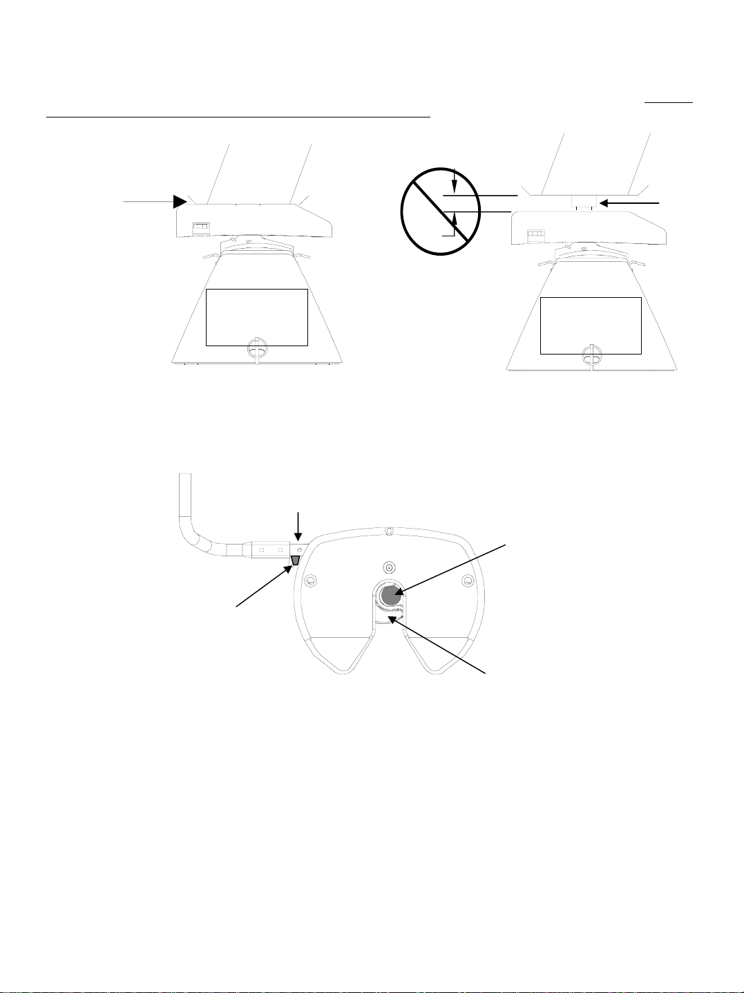
7. Pull hitch handle out completely until it latches in open position so that king pin is no longer
securely grasped by hitch jaws (see Figure 4). Trailer is now free from hitch and truck. If handle does not pull out,
there is probably pressure against the jaw. To relieve this pressure, back the truck slightly. Reset truck emergency
brake. Then pull hitch handle out completely until it latches in open position.
8. AFTER MAKING CERTAIN NO ONE IS STANDING BETWEEN TRUCK AND TRAILER OR IN FRONT OF TRUCK,
drive truck slowly away from trailer.
9. Hitch jaw will automatically close as the king pin is removed from the jaw.
10. KEEP WHEEL BLOCKS IN PLACE. This will keep trailer from moving unexpectedly
WARNING:
Trailers that are not stable or properly hitched can fall and cause death or serious injury!
To avoid death or serious injury:
• All trailer tires MUST be blocked in front and behind each tire AND
• Trailer landing gear MUST be resting on firm ground AND
•TruckMUSTbe stationary, in park, with emergency brake on!
WARNING
Whenever possible, avoid putting body under trailer or between truck and trailer
If you need to place any part of our body under trailer or between truck and trailer:
•All trailer tires MUST be blocked in front and behind each tire AND
•Trailer landing gear MUST be resting on firm ground AND
•Truck MUST be stationary, in park, with emergency brake on!
1. Recheck tightness of all hardware every 1000 miles of use. All 5/8” bolts have a torque specification of 170ft.lbs.,
and 1” jam nuts should be box wrench snug plus1/4 turn(see assembly instruction, 30058IN, for more detail).
2. See “Before each trip” section in this manual.
3. Anchor assemblies should be lubed every 6 months with lithium grease to keep assemblies moving freely.
MAINTENANCE:
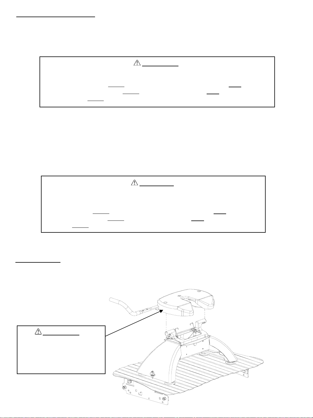
Figure 10 : Head Placement
WARNING:
Tilting 5th Wheel head can
crush and cut. Keep hands and
fingers clear from this area at
all times (including
placement/removal of head).
6
30059OP - 15MAR05D PCN7735 ©2005 CEQUENT TOWING PRODUCTS, INC LITHO IN USA
FOR KITS 30059, 40259 & 50259

HITCH INSTALLATION:
1. Remove puck plugs from all (4) of the pucks in the truck bed(Figure 11) and store for use when hitch is removed.
2. Set Signature Series hitch onto the pucks, and rotate handles into unlocked position(approximately perpendicular with
base arch, Figure 12) until hitch drops into pucks on all (4) corners.
3. Rotate (4) handles into locked position(with locking holes through base arch shell) and overlapped on each
side(Figure 13).
4. Place lynch pins / locks through the overlapping handle holes on each side to anchor hitch into pucks(Figure 1).
5. KEEPING HANDS AND FINGERS AWAY FROM THE PINCH POINTS ON EACH SIDE OF THE HEAD, place head
onto center section(Figure 10). Head should tilt rearward on the torsion springs.
6. Insert pull pin and clip on each side of the head to attach to the hitch center section(Figure 1).
7. Pull up on head to test that all attachments have been completed properly and hitch is ready to tow.
HITCH REMOVAL:
1. Remove pull pin and clip from each side of the head(Figure 1).
2. KEEPING HANDS AND FINGERS AWAY FROM THE PINCH POINTS ON EACH SIDE OF THE HEAD, lift head off
center section(Figure 10). Store where dirt and debris will not get inside jaw mechanism.
3. Remove lynch pin / lock from the overlapping handle holes on each side of the hitch(Figure 1). Store lynch pins.
4. Rotate (4) handles into unlocked position(perpendicular with base arch shell, Figure 12). Lift each side of hitch out of
pucks separately, handles may have to be jiggled slightly to align anchors with puck holes to remove.
5. Store hitch in dry place where dirt and debris will not get into anchor assemblies.
6. Press puck plugs(packed with mounting kit) into all (4) of the pucks in the truck bed to keep debris out of pucks(Figure
11).
Figure 12: Anchor
Handles in Unlocked
Position
Figure 13: Anchor
Handles in Locked
Position(overlapped)
Locking Hole Tabs in
Handles overlap and
Protrude through Base
Arch
Figure 11: Puck Plugs
Truck Bed
Puck Plug
Puck
7
30059OP - 15MAR05D PCN7735 ©2005 CEQUENT TOWING PRODUCTS, INC LITHO IN USA
FOR KITS 30059, 40259 & 50259

REF # QTY. DESCRIPTION
1 1 HEAD ASSEMBLY
2 1 CENTER SECTION
32BASEARCH
4 1 HANDLE TUBE
5 1 HANDLE GRIP
6 4 5/8-11 GR8 HEX HEAD BOLT
745/8LOCKWASHER
8 2 1/4-20 GR2 HEX HEAD BOLT
92TUBESPACER
10 2 TORSION SPRING
11 2 3/8 CARRIAGE BOLT
12 2 3/8 NUT
13 2 3/8 LOCK WASHER
14 2 1/2” PULL PIN
REF # QTY DESCRIPTION
15 2 SPRING RETAINING CLIP
16 4 WASHER
17 1 HANG TAG
18 4 ANCHOR, BUSHING
19 4 ANCHOR, TEE PIN
20 2 HANDLE, LT ANCHOR
21 2 HANDLE, RT ANCHOR
22 6 LYNCH PIN
23 4 1” NUT
24 4 TAB WASHER
25 1 LABEL, PINCH POINT
26 1 LABEL, OPERATING WARNING
27 1 LABEL, ANCHOR PIN
28 1 LABEL, WARNING
29 1 LABEL, RATING 1
Figure 14
4
1
26
11
12
14
15
525
10
9
28
16
23
20
3
22
27
6
7
2
21
17
13
22
18
19
29
8
24
8
30059OP - 15MAR05D PCN7735 ©2005 CEQUENT TOWING PRODUCTS, INC LITHO IN USA
FOR KITS 30059, 40259 & 50259

NOTES
SEVEN YEAR LIMITED WARRANTY
Hitches - Custom Receivers
Cequent Towing Products warrants the Signature Series 5th Wheel Hitch from date of purchase against
defects in material and workmanship under normal use and service, ordinary wear and tear excepted, for
7 years of ownership to the original consumer purchaser when a Cequent Towing Products mounting kit is
used.
Cequent Towing Products will replace FREE OF CHARGE any part which proves defective in material or
workmanship when presented to any Cequent Towing Products dealer, Cequent Towing Products
Warehouse or returned to factory. TRANSPORTATION CHARGES PREPAID, at the address below.
THIS WARRANTY IS LIMITED TO DEFECTIVE PARTS REPLACEMENT ONLY. LABOR CHARGES
AND/OR DAMAGE INCURRED IN INSTALLATION OR REPLACEMENT AS WELL AS INCIDENTAL
AND CONSEQUENTIAL DAMAGES CONNECTED THEREWITH ARE EXCLUDED.
Some states do not allow the exclusion or limitation of incidental or consequential damages, so the above
limitation or exclusion may not apply to you.
Any damage to the 5th Wheel Hitch as a result of misuse, abuse, neglect, accident, improper installation,
or any use violative of instructions furnished by us, WILL VOID THE WARRANTY.
This warranty gives you specific legal rights, and you may also have other rights which vary from state to
state. In the event of a problem with warranty service or performance, you may be able to go to a small
claims court, or a federal district court.
Cequent Towing Products, Inc.
2602 College Avenue
Goshen, IN 46528
9
30059OP - 15MAR05D PCN7735 ©2005 CEQUENT TOWING PRODUCTS, INC LITHO IN USA
FOR KITS 30059, 40259 & 50259
Other manuals for Signature Series
1
This manual suits for next models
3
Table of contents
Other Cequent Towing Products Automobile Accessories manuals