Cequent Towing Products Signature Series User manual

Part Numbers:
30074
Rev. F6-27-0730074NSheet 1 of 11
z2006, 2007 Cequent Towing Products
Installation Instructions
READ THOROUGHLY BEFORE BEGINNING
Signature Series Rail Kit
Dodge Ram Trucks-all, including Mega-cabs
GUIDELINES FOR MATCHING TOW VEHICLE AND TRAILER
WARNING:
Failure to follow all of these instructions may result in death or serious injury!
INDEX
WARNING:
Failure to check and follow tow ratings could result in tow vehicle
damage or truck and trailer separation while towing.
•Trailer and its contents together must not exceed truck, hitch and/or trailer tow
ratings.
•Towing vehicle must have a manufacturer’s rated towing capacity equal to or
greater than the gross trailer weight (dry weight of the trailer plus payload of the
trailer). Figure1.
•Gross weight of trailer must not exceed fifth wheel hitch rating.
•King pin weight must not exceed fifth wheel rating, Figure 2. If in doubt have king
pin weight measured by a qualified technician.
1. GUIDELINES FOR MATCHING TOW VEHICLE AND TRAILER. Pages 1 - 3
2. DRILLED AND BOLTED INSTALLATION FIGURE. Page 4
3. NO-DRILL, CLAMPED ON INSTALLATION FIGURE. Page 5
4. ASSEMBLY INSTRUCTIONS. Pages 6 – 10
5. CEQUENT TOWING PRODUCTS SEVEN YEAR LIMITED WARRANTY. Page 11
FACTORY TRAILER + FULL WATER
TANKS + CARGO, ETC.
= GROSS TRAILER WEIGHT
Figure1.
1. Check Tow Ratings:
Vehicle Tow Rating:_______________________.
Signature Series Hitch Rating:__________________.
Gross Trailer Weight Figure 1:______________.
*Trailer weight should be the lowest of these recorded ratings for safe towing conditions.
2. Cequent Towing Products hitches are designed for use with recreational fifth wheel trailers only. Hitch applications other than
recreational fifth wheel trailers must be approved in writing by Cequent Towing Products Engineering Department.
3. Use only a SAE 2-inch kingpin with your Signature Series Fifth Wheel Hitch.
4. Approximately 15%-25% of trailer weight should be on hitch (Pin Weight), Figure2.
15-25%
GROSS TRAILER
WEIGHT
(PIN WEIGHT)
75-85%
GROSS TRAILER
WEIGHT
Figure 2.

Part Numbers:
30074
Rev. F6-27-0730074NSheet 2 of 11
z2006, 2007 Cequent Towing Products
Installation Instructions
READ THOROUGHLY BEFORE BEGINNING
Signature Series Rail Kit
Dodge Ram Trucks-all, including Mega-cabs
KING PIN
RV TRAILER
TRUCK
Figure 3.
Rule of thumb: The distance from the back of the truck cab to the center of the rear truck
axle (“X” in Figure 3), should be approximately 4 inches greater than one-half
the trailer width (“Y” in Figure 3).
Conventional Pin Box Extended Pin Box
Figure 4.
WARNING:
Do Not install this fifth wheel hitch on or attempt to tow with a short bed pickup
truck that has a bed shorter than 6 ft.!
Approximately 6 Inches
Level Trailer
Figure 5.
CAUTION:
The measurements above are guidelines. If your measurements are close to these numbers re-check clearances.
If vehicle and/or trailer has any added bed vicinity accessories (i.e. fairings, air dams, ground effects, bed rails, etc.).
Additional dimensioning and clearance checks have to be made.
5. Trucks come in many different configurations. Cequent Towing Products hitches are designed for use in light trucks such as
the Ford F-Series, the Chevy Silverado and the Dodge Ram. Cequent Towing Products recommends the use of long bed (8ft)
light trucks for the best combination in truck - trailer turning clearance.
6. If a short bed pickup (less than 8 ft. but longer than 6 ft.) is to be used for towing, Cequent Towing Products recommends the
trailer be equipped with an extended pin box to help gain additional truck - trailer turning clearance (See trailer manufacturer for
options), Figure 4. It also may be helpful to add a Signature Series Slider (Part # 30070) for increased turning clearance for low
speed, non-highway maneuvering.
7. The height of the hitch and the pin box should be adjusted so the trailer is approximately level as it is towed. Allow
approximately 6 inches clearance between the top of the pickup walls and the underside of the front of the trailer for pitch and
roll of the trailer, Figure 5. Allow more clearance between pickup walls and trailer for off road use.

Part Numbers:
30074
Installation Instructions
READ THOROUGHLY BEFORE BEGINNING
Rev. F6-27-0730074NSheet 3 of 11
z2006, 2007 Cequent Towing Products
Signature Series Rail Kit
Dodge Ram Trucks-all, including Mega-cabs
B
D
C
A
*MEASURED WITH TRAILER LEVEL,
ON LEVEL GROUND
WARNING:
•Connection for trailer wiring must be located at the side of the truck bed between the driver’s
seat and the rear wheel to prevent operators from working between the truck and trailer.
•Avoid putting any part of your body under the trailer or between the truck and trailer.
Unexpected or accidental movement of the truck or the trailer can cause serious injury or death
•If you must place any part of your body under the trailer or between the truck and trailer you
MUST perform ALL of the following steps:
•Check that the truck transmission is in park
•Check that the emergency brake is on
•Block in front of and behind all trailer tires
•Check that the trailer landing gear are resting on firm ground
8. Hitch height determination:
With trailer leveled and on level ground measure from the ground to the king pin box (“A” in Figure 6). Secondly measure from
the height of the inside of the truck bed (“B” in Figure 6). Determine the amount of clearance over the side rails ( “C” and “D” in
Figure 6), as mentioned in Note 7.
Hitch Height = A – B + 2”
The 2” value is an estimate of suspension compression due to king pin weight of the trailer. This compression could range
between 1”-5” depending on the truck being used and the trailer being towed.
D – C + 2” > 6” as in Note 7.
9. If a lube plate is to be used with a Signature Series 5th Wheel it must be at least 12” in diameter. Cequent Towing Products
offers this optional lube plate as part # 83001 / 40001.
Figure 6.

Installation Instructions
READ THOROUGHLY BEFORE BEGINNING
Signature Series Rail Kit
Dodge Ram Trucks-all, including Mega-cabs
Part Numbers:
30074
Rev. F6-27-0730074NSheet 4 of 11
z2006, 2007 Cequent Towing Products
1
2
3
4
This is a magnified
view of a bolt leader
Equipment Required:
Fastener Kit: 30074F
Sockets & Wrenches: 3/8” Hex Socket, 3/4”, 7/8”,15/16”
Drill Bits: 3/16”, 21/32”, 2-1/2” Hole Saw or Knockout Punch.
Other Tools: Measuring tape, Sheet metal cutters, Files (round &
flat), Hammer, Center punch, Torque wrench, Hand drill, Various
socket extensions & adaptors,
5/8”-11 X 3-1/2” bolt, pointedQty. (1)
5/8” Flat washerQty. (4)
5/8” Lock washerQty. (12)
1/4” X 1-1/2” X 2” Block, Hole in center, use as
needed.
Qty. (4)
5/8-11 X 1-1/2” Gr. 8 Hex bolt.Qty. (4)
Trim ringQty. (4)5/8”-11 Hex nutQty. (4)
PuckQty. (4)5/8” Bolt leader – 32”Qty.(2)
5/8”-11 Button head screwQty. (4)5/8-11 X 1-1/2” GR.8 Ribbed neck boltQty. (4)
2
WARNING: This hitch is designed to safely carry the loads
specified. Under no circumstances do we recommend exceeding the
towing vehicle manufacturers recommended vehicle towing capacity.
Passenger’s side
truck frame rail
1-1/4” to 1-3/8” dia. hole bottom of
frame approx. 26” rear of axle.
Alternative slot
for bolt leader on
inside of frame
rail approx. 21”
rear of axle.
6
7
8
9
1059
8
All hitch fasteners & brackets typical
both sides of vehicle,
Hitch rear
cross rail
Driver’s side
truck frame rail
Figure 7.
Drilling required.
Bolt-on configuration.
Passenger’s side
Hitch frame bracket
Driver’s side
Hitch frame bracket
5
654
5
2
1
NOTE:
Truck bed not shown
for clarity. All frame
holes and slots
typical on both sides
of vehicle.
2500/3500/Mega-cab
frame shown, 1500
non Mega-cab frame
slightly different.
NOTE! This hitch can be installed either by clamping-on or bolting-on.
Figure 7. below shows how to drill and bolt on.
Figure 8. on next page shows how to clamp-on.
(2) places
typical both sides
Drill (2) places.
Typical both sides. See
instructions for proper
location before drilling.
Brake line
Truck front
cross member
10
11
7
This is a magnified view of
the pointed bolt.
(2) places
typical both sides
11
(4) places Hitch front cross rail.
3

Hitch rear cross rail.
Cut away to show detail.
1
14
13
2
*8
1
13
2
3
Hitch front
clamp bracket
Hitch spacer bracket
NOTE:
Truck bed not shown
for clarity. All frame
holes and slots
typical on both sides
of vehicle.
2500/3500/Mega-cab
frame shown, 1500
non Mega-cab frame
slightly different.
Installation Instructions
READ THOROUGHLY BEFORE BEGINNING Part Numbers:
30074
Equipment Required:
Sockets & Wrenches: 3/8” Hex Socket, 3/4”, 7/8”,15/16”
Drill Bits: 3/16”, 21/32”, 2-1/2” Hole Saw or Knockout Punch.
Other Tools: Measuring tape, Sheet metal cutters, Files (round &
flat), Hammer, Center punch, Torque wrench, Hand drill, Various
socket extensions & adaptors.
Fastener Kit: 30074F WARNING:This hitch is designed to safely carry the loads
specified. Under no circumstances do we recommend exceeding the
towing vehicle manufacturers recommended vehicle towing capacity.
Rev. F6-27-0730074NSheet 5 of 11
z2006, 2007 Cequent Towing Products
All hitch fasteners & brackets typical
both sides of vehicle, except
*8
NOTE! This hitch can be installed either by clamping-on or bolting-on.
Figure 7. previous page shows how to drill and bolt on.
Figure 8. below shows how to clamp on.
Figure 8.
No drilling required.
Clamp-on configuration.
Signature Series Rail Kit
Dodge Ram Trucks-all, including Mega-cabs
1
2
3
4
5/8”-11 X 3-1/2” bolt, pointedQty. (1)
1/4” X 1” X 2” Block
Qty. (2)
14
5/8” Flat washerQty. (4)
2.65” Tubular spacer, (Yellow zinc).
Qty. (4)
13
5/8” Lock washerQty. (8)
1/4” X 1-1/2” X 2” Block, Off-center hole, use as
needed.
Qty. (2)
3” Tubular spacer
Qty. (4)
12
5/8-11 X 1-1/2” Gr. 8 Hex bolt.Qty. (4)
Trim ringQty. (4)1/2”-13 Hex nutQty. (8)
PuckQty. (4)1/2” Conical washerQty.(8)
5/8”-11 Button head screwQty. (4)1/2-13 X 4-1/2” Grade 8 Carriage boltQty. (8)
6
7
8
9
5
10
11
654
(2) places.
Typical both sides
Driver’s side
Hitch frame bracket
Driver’s side
truck frame rail
Passenger’s side
truck frame rail
Brake line
Truck front
cross member
Passenger’s side
Hitch frame bracket
1059 11
(4) places typical
Hitch front cross rail.
7
This is a magnified view of
the pointed bolt
Hitch rear
clamp bracket
3
3
2
12
1

Installation Instructions
READ THOROUGHLY BEFORE BEGINNING Part Numbers:
30074
Rev. F6-27-0730074NSheet 6 of 11
z2006, 2007 Cequent Towing Products
Signature Series Rail Kit
Dodge Ram Trucks-all, including Mega-cabs
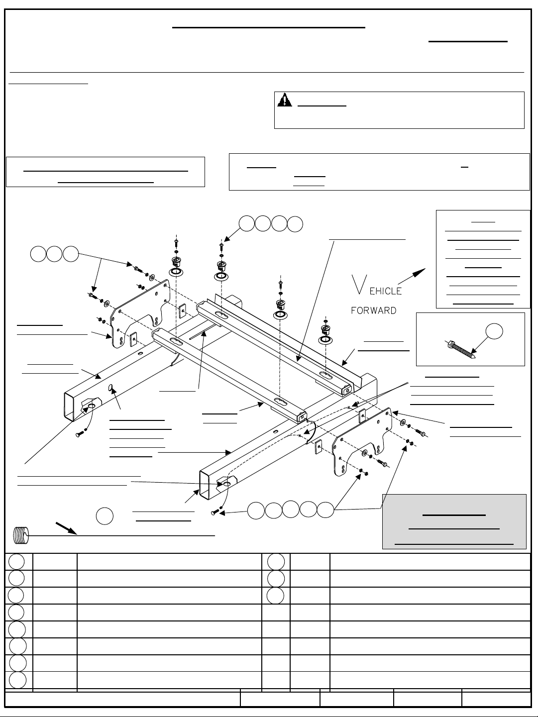
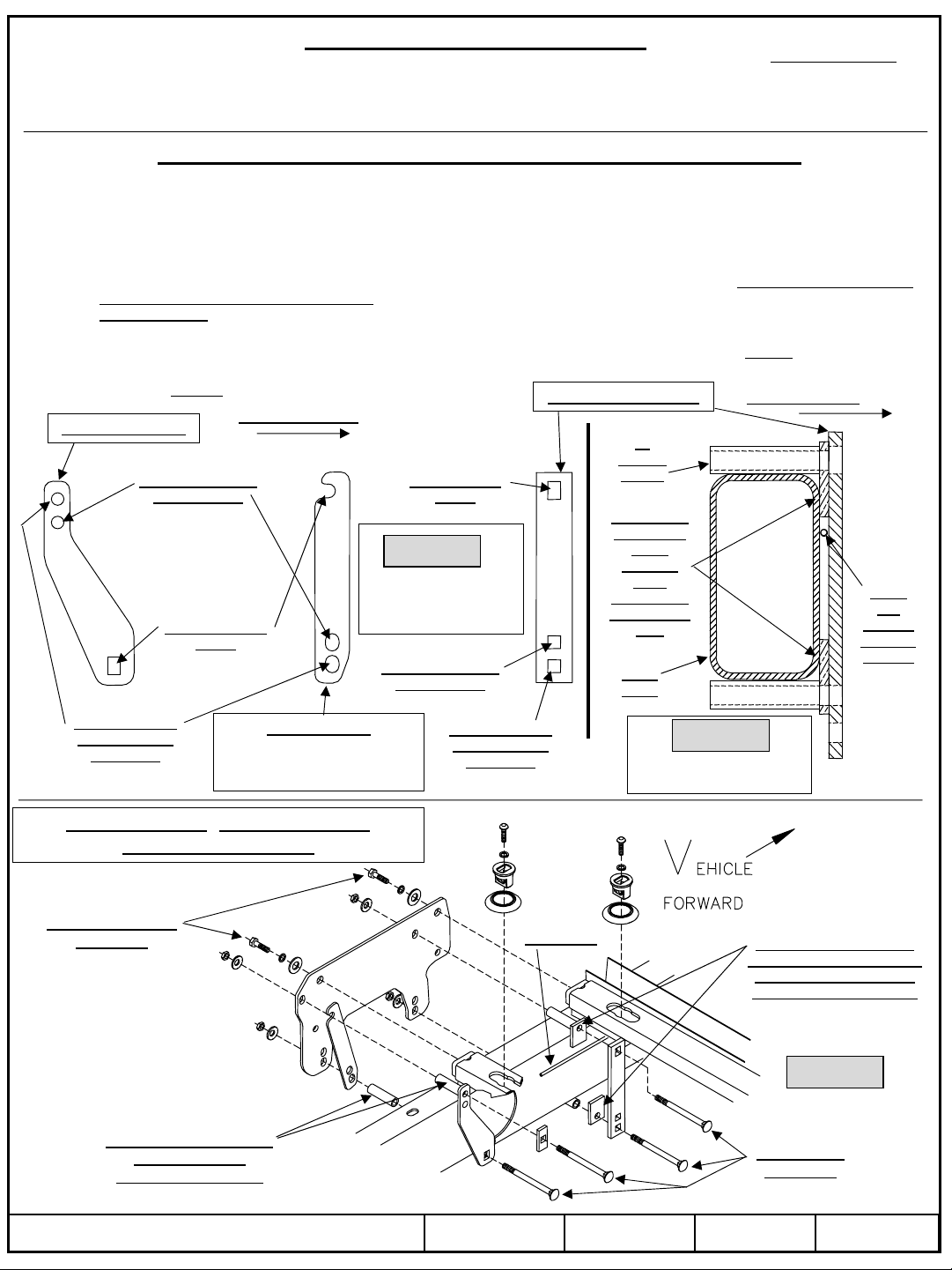
1. The following instructions should be used to mount the 5th wheel. Care and attention to detail will ensure a quick quality
installation. Check parts against parts list to become familiar with parts in kit, Figures 7 & 8.
2. It may help to raise rear of truck on hoist or jack stands high enough to allow easier installation of hitch. This will provide
maximum room to install the 5th wheel brackets. It is optional to remove or loosen truck bed also.
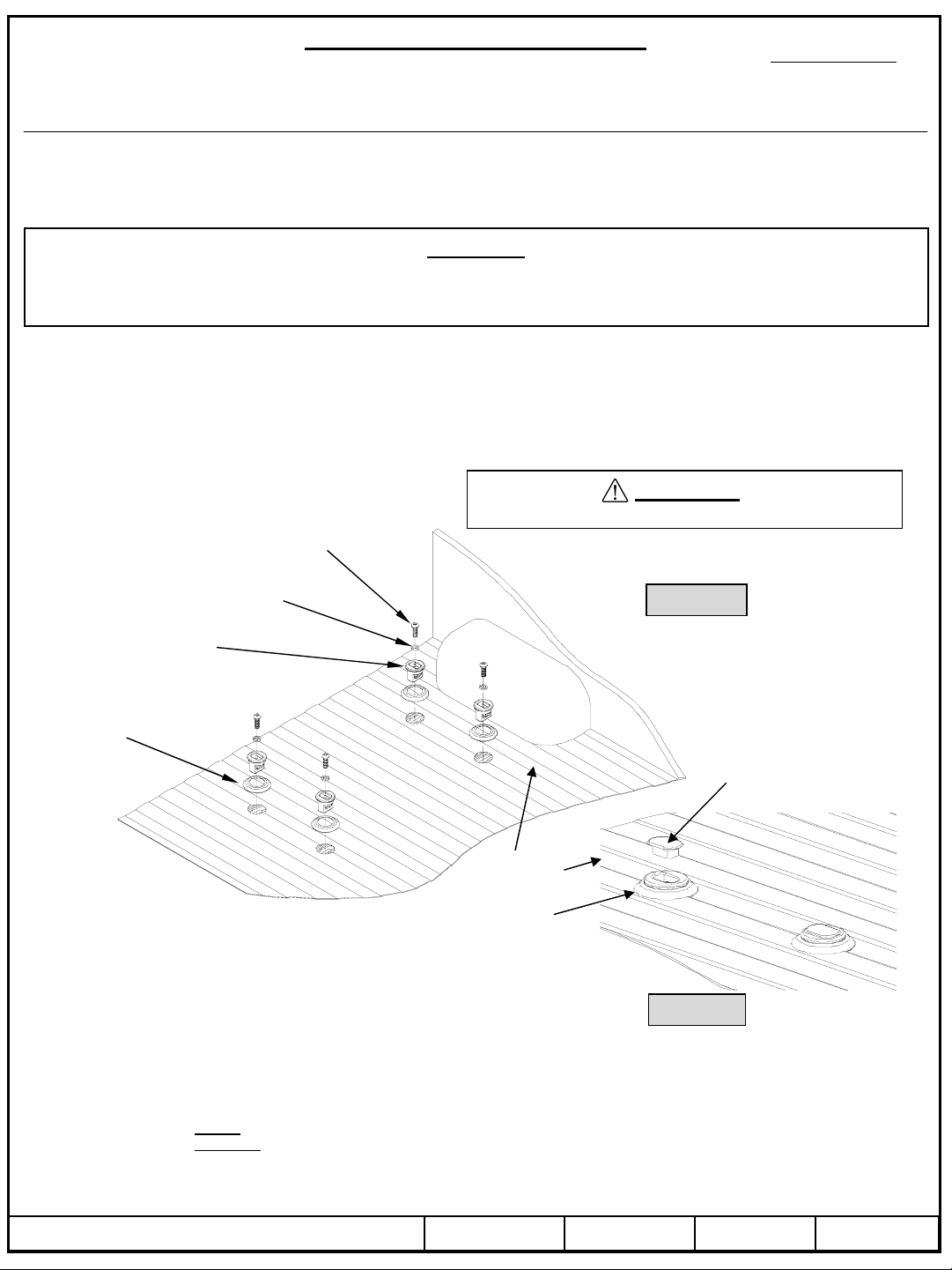
3. Plastic drop-in bed liners must be cut out of the way. Remove plastic bed liner if applicable. Spray-in bed liners and bed
mats less than 1/4” thick will work with normal installation instructions. Note: Consult installer for recommended curing time
on spray-in liner before cutting holes through bed.
4. Use only CEQUENT TOWING PRODUCTS supplied bolts, nuts, and washers to install this kit.
5. These instructions are intended for a specific group of trucks. If these instructions do not apply to your vehicle, contact
Technical Service to get proper instructions. Each frame bracket must be bolted to the vehicle frame with two bolts. Or
clamped with supplied components and hardware as shown in these instructions.
ASSEMBLY INSTRUCTIONS FOR FIFTH WHEEL INSTALLATION
WARNING:
If the truck is raised or truck bed is to be loosened or removed be sure that truck is properly blocked and restrained to prevent
the truck and or bed from falling. Failure to do so may result in the truck and or bed falling, causing death or serious injury.
CAUTION:
Check for obstructions before drilling. Failure to do so could result in damaged fuel or brake lines, structural members,
etc. CEQUENT TOWING PRODUCTS does its best to communicate tow vehicle manufacturer changes; however, it is
ultimately the responsibility of the installer to prevent damage due to installation.
CAUTION:
These instructions are guidelines only. Actual installation is the responsibility of the installer and the owner. Always
measure truck and trailer before installing hitch to be sure that there is clearance at the cab and at the bumper to allow for
turns.
CAUTION!
Read pages 1-3 of these instructions before starting installation. Failure to do so could result in significant vehicle damage!
6. Insert rails as shown in the following steps for Non-Mega-cab trucks, Figures 9 through 14.
For Mega-cab trucks see line 6a. next page.
TOOLS
3/16" Drill 15/16" Socket & Open End Wrench 200 lb-ft / 271 N*M Torque Wrench Center Punch
21/32" Drill 3/4” Socket & Open End Wrench 2-1/2” Hole Saw or Knockout Punch Tape
3/8” Hex socket 7/8” Socket & Open End wrench Measuring Tape Hammer
Truck Forward
Top View
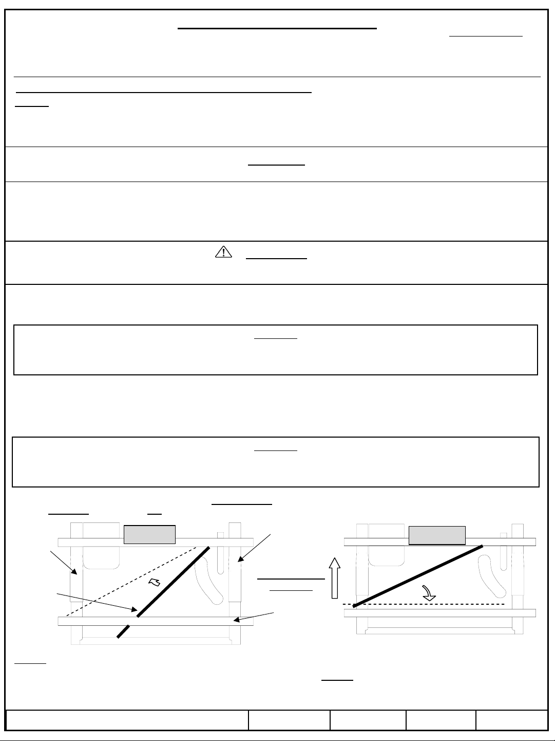
Step 1 : Slide a cross rail in at an angle from driver’s side wheel
well between spring and bottom of frame rear of axle and over
the axle and in front of the exhaust on passenger side. Lift and
rotate it so that it rests on the frame (Driver’s side), Figure 9.
Exhaust
Step 2 : Continue rotating the rail up and over the
exhaust so that it is against the rear truck cross
member , Figure 10.
Driver’s
side
frame
Passenger’s
side frame
Fuel
tank
Rear truck
cross member
Hitch
cross rail
Figure 9. Figure 10.

30074
Rev. F6-27-0730074NSheet 7 of 11
z2006, 2007 Cequent Towing Products
Step 3 : Slide the rail across so that it extends over
the frame on the passenger side and does not rest
on the frame on the Driver’s side.
Step 5 : Rotate the rail up and over the exhaust so
that it is against the rear rail.
Step 6 : Slide the front rail forward with both ends
resting on the frame. Slide the rear rail to the left so
that it rests evenly on both sides of the frame.
Figure 11.
Figure 13.
Figure 14.
Figure 12
Installation Instructions
READ THOROUGHLY BEFORE BEGINNING Part Numbers:
Signature Series Rail Kit
Dodge Ram Trucks-all, including Mega-cabs
Truck
Forward
Top View
Do not use
these steps
for Mega-cab
trucks. See
Step 6a.
Below.
Step 4 : Insert the front rail in the same manner as
the rear rail so that it rests on the frame
(Driver’s side).
NOTE! Mega-cab trucks require that you install
the cross rails in either of the options below.
Hitch
cross rail
6a.
Option A:
Drop exhaust tailpipe system to install hitch cross rails and
follow steps 1-6 above.
Option B:
Loosen or remove truck bed from frame to allow access to slide
hitch cross rails across top of frame from Driver’s side wheel
opening. By loosening all (4) truck bed bolts you may be able to tilt
truck bed up on Driver’s side to slide hitch cross rails across top of
truck frame without removing bed completely.

30074
Installation Instructions
READ THOROUGHLY BEFORE BEGINNING Part Numbers:
Signature Series Rail Kit
Dodge Ram Trucks-all, including Mega-cabs
Rev. F6-27-0730074NSheet 8 of 11
z2006, 2007 Cequent Towing Products
7. After hitch cross rails are in place determine if hitch frame brackets are to be bolted to truck frame or clamped to truck frame.
If Drilling and bolting to frame proceed below.
If clamping to frame go to line 23 and follow directions for a No-Drill clamp-on installation.
8. Loosely attach frame brackets to rails using 5/8” X 1-1/2” long bolts, flat washers & lock washers. See Figure 7 & 22.
9. Slide rail assembly as far rearward as possible then using frame bracket as template, and after checking rails are square with
each other, drill pilot holes in frame. Enlarge pilot holes to 21/32” diameter holes, Figure 7. Optional: Spray under coating
around drilled holes to prevent rusting.
10. Thread 5/8” x 1-1/2” rib-neck bolt onto pull wire, Figure 15. Insert straight end of pull wire into access hole and guide wire
through drilled mounting holes. Pull wire out through mounting hole to position rib neck bolt for connecting rail bracket and
chassis rail, Figure 7. Repeat process for all four rib neck bolt locations.
11. Loosely attach frame brackets to frame using 5/8” x 1-1/2” rib-neck bolts, spacers, lock washers, and nuts; fasten until hand
tight, Figure7.
12. Using pointed bolt, Figure 16, screw pointed bolt in to the nuts that are welded to the rail assembly until a prick mark is
visible in the truck bed. Access to some welded nuts can be obstructed by other truck components; the other prick mark/s
must be measured from the other prick marks, Figure 17. If you have a plastic bed liner cut 19” X 4” slots in plastic drop-in
bed liner measured from prick marks in truck bed. If the Signature Series slider fifth wheel assembly is used, then see fifth
wheel slider assembly instructions for slot cut dimensions.
CAUTION:
Check for obstructions before drilling. Failure to do so could result in damaged fuel or brake lines, structural
members, etc. CEQUENT TOWING PRODUCTS does its best to communicate tow vehicle manufacturer
changes; however, it is ultimately the responsibility of the installer to prevent damage due to installation.
Pull wire
Figure 15.
5/8” Rib-neck bolt
CAUTION:
It is important that 21/32" drill be used for holes in chassis
frame as rib-neck bolts may break if too small a hole is
used and neck may not grip if too large a hole is used.
Figure 16.
Figure 17.
30"
2"
3"
19"
4"
13"
**Measure distance for
cutting plastic bed liner.
Prick
mark/s
Truck bed
Looking from
above Tailgate
(open)
Forward
Prick mark/s. May have to measure
and center punch from above.
Measure diagonally to check
squareness.
Cut bed liner
Cut bed liner

30074
Installation Instructions
READ THOROUGHLY BEFORE BEGINNING Part Numbers:
Signature Series Rail Kit
Dodge Ram Trucks-all, including Mega-cabs
Rev. F6-27-0730074NSheet 9 of 11
z2006, 2007 Cequent Towing Products
CAUTION:
Check for obstructions before drilling. Failure to do so could result in damaged fuel or brake lines, structural
members, etc. CEQUENT TOWING PRODUCTS does its best to communicate tow vehicle manufacturer
changes; however, it is ultimately the responsibility of the installer to prevent damage due to installation.
13. Remove 5/8” x 1 1/2“ bolts attaching frame bracket to mounting rails. Move rails rearward or forward to prevent
interference with hole drilling or punching of the truck bed.
14. Drill pilot holes in truck bed at prick mark locations. With hole saw or knockout punch create 2 1/2” hole centered at pilot
holes. Note: Consult installer for recommended curing time on spray-in liner before cutting holes through bed.
Optional: Spray under coating around 2 1/2” holes to prevent rusting.
15. Loosely reattach rails to frame bracket.
16. From truck bed attach pucks and trim rings to rails, Figure 18, using 5/8” button head screw and lock washer. Tighten to
100ft.lbs. / 136 N*M torque.
17. Insert plugs in pucks whenever they are not in use, Figure 19.
18. Torque hitch assembly bolts per hitch instructions.
19. Torque all 5/8” cross rail hex bolts and frame bracket hex nuts to 170ft.lbs. / 230 N*M.
20. Torque all 1/2” clamping bolts to 75 ft. lbs. / 102 N*M.
21. Replace any brake lines and spare tire that may have been removed or relocated.
22. You are done. Check that all essential truck components (brakes, lights, etc.) are in proper working order before returning
truck to owner. Recheck that all hitch fasteners are torqued to proper amounts. Explain essential Warnings and Cautions
to vehicle owner that are in these instructions. Explain Warranty that covers this hitch. Give these instructions / warranty
to vehicle owner.
WARNING:
DO NOT lubricate threads. It may cause bolt failure.
Figure 18.
5/8” BUTTON HEAD
4 PLACES
PUCK
4 PLACES
TRIM RING
4 PLACES
5/8” LOCK WASHER
4 PLACES
Figure 19.
Truck Bed
Puck Plug
Puck Assembly

Rev. F6-27-0730074NSheet 10 of 11
z2006, 2007 Cequent Towing Products
30074
Installation Instructions
READ THOROUGHLY BEFORE BEGINNING Part Numbers:
Signature Series Rail Kit
Dodge Ram Trucks-all, including Mega-cabs
23. Loosely attach hitch frame brackets to hitch cross rails using 5/8” X 1-1/2” long bolts, flat & lock washers,
See Figure 8 & Figure 22. Forward hitch cross rail will be up close to truck bed cross member.
24. Install all hitch clamps, spacer brackets & tubular spacers and bolts as shown in Figure 8 & 22. On 1500 non Mega-cab
truck frames you will use different holes on the forward, rearward clamps & spacer brackets than on 2500/3500 &
1500/2500/3500 Mega-cab frames. This is because of frame height differences. See Figure 20. for proper hole usage.
On some trucks including newer 1500 non Mega-cab trucks it is required to block out forward hitch clamp on inside of
Driver’s side frame rail to go around brake line that runs along inside of frame, See Figure 21. Make sure to orient blocks
with longer side towards middle of frame. Tape the blocks to the clamp bracket before installing. Make sure to use shorter
YELLOW ZINC tubular spacers on all rearward clamps, See Figure 22.
25. When all brackets are properly positioned and square with each other and the truck frame and watching not to clamp down
on any brake lines, wiring or other vehicle apparatus you can loosely tighten clamping hardware. Do not torque clamping
or cross rail bolts yet.
26. Return to Line 12 previous pages and proceed from there.
THE FOLLOWING STEPS APPLY FOR NO-DRILL, CLAMP-ON ONLY
Rear clamp bracket
Forward clamp bracket
Spacer bracket.
used on outside of frame for
rear attachment when
clamping only.
Use these on 1500
non Mega-cab
Use these on all
trucks
TRUCK FORWARD
Use these on all
2500/3500 & all
Mega-cabs
Use this on all
trucks
Use these on 1500
non Mega-cab
Use these on all
2500/3500 & all
Mega-cabs
Showing correct hole
usage for clamp
brackets.
Looking forward along
Driver’s side frame rail
TRUCK INBOARD
Truck
frame
1/4” Blocks.
Use tape to
orient
correctly
while
assembling.
Driver’s side
only
Brake
line
location
on some
models.
3”
Tubular
spacer
Figure 20.
Figure 21.
Blow-up of Figure 8. Driver’s side shown,
Passenger’s side opposite
Figure 22.
Use shorter yellow zinc
tubular spacers
rearward both sides.
5/8” X 1-1/2” Bolts
Gr.8 Bolts Use offset hole blocks to
space around brake line on
1500 Non Mega-cab only.
And on Driver’s side only.
Brake line
1/2” X 4-1/2”
Gr.8 Bolts

Rev. F6-27-0730074NSheet 11 of 11
z2006, 2007 Cequent Towing Products
30074
Installation Instructions
READ THOROUGHLY BEFORE BEGINNING Part Numbers:
Signature Series Rail Kit
Dodge Ram Trucks-all, including Mega-cabs
NOTES
SEVEN YEAR LIMITED WARRANTY
Hitches - Custom Receivers
Cequent Towing Products warrants the Signature Series 5th Wheel Hitch Mounting Kits from date of purchase
against defects in material and workmanship under normal use and service, ordinary wear and tear excepted,
for 7 years of ownership to the original consumer purchaser when a Cequent Towing Products Signature Series
5th Wheel Hitch is used.
Cequent Towing Products will replace FREE OF CHARGE any part which proves defective in material or
workmanship when presented to any Cequent Towing Products dealer, Cequent Towing Products Warehouse or
returned to factory. TRANSPORTATION CHARGES PREPAID, at the address below. THIS WARRANTY IS LIMITED
TO DEFECTIVE PARTS REPLACEMENT ONLY. LABOR CHARGES AND/OR DAMAGE INCURRED IN
INSTALLATION OR REPLACEMENT AS WELL AS INCIDENTAL AND CONSEQUENTIAL DAMAGES
CONNECTED THEREWITH ARE EXCLUDED.
Some states do not allow the exclusion or limitation of incidental or consequential damages, so the above limitation
or exclusion may not apply to you.
Any damage to the Signature Series 5th Wheel Hitch as a result of misuse, abuse, neglect, accident, improper
installation, or any use violative of instructions furnished by us, WILL VOID THE WARRANTY.
This warranty gives you specific legal rights, and you may also have other rights which vary from state to state. In the
event of a problem with warranty service or performance, you may be able to go to a small claims court, or a federal
district court.
Cequent Towing Products, Inc.
47774 Anchor court West
Plymouth, Michigan 48170
Other manuals for Signature Series
1
This manual suits for next models
1
Table of contents
Other Cequent Towing Products Automobile Accessories manuals