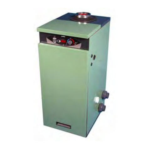
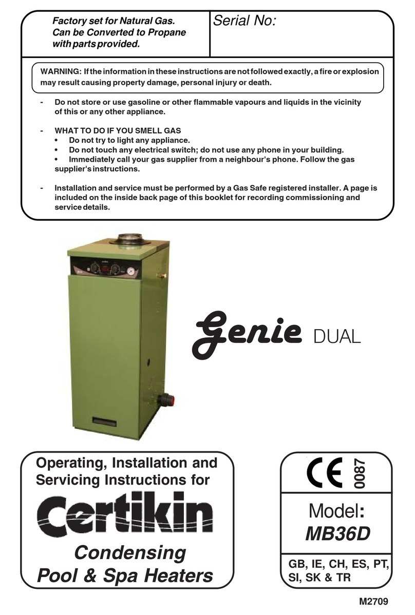
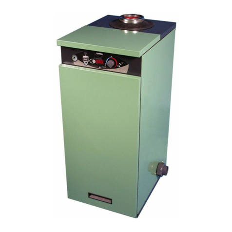
Certikin MB35S User manual

WARNING: If the information in these instructions are not followed exactly, a fire or
explosion may result causing property damage, personal injury or death.
- Do not store or use gasoline or other flammable vapours and liquids in the vicinity
of this or any other appliance.
- WHAT TO DO IF YOU SMELL GAS
• Do not try to light any appliance.
• Do not touch any electrical switch; do not use any phone in your building.
• Immediately call your gas supplier from a neighbour's phone. Follow the gas
supplier's instructions.
- Installation and service must be performed by a Corgi registered installer. A page is
included on the inside back page of this booklet for recording commissioning and
service details.
Operating, Installation and
Servicing Instructions for
Condensing
Pool & Spa Heaters
M2709
!"#$%:
MB35S
MB50S
0087
Genie
Serial No:
Factory set for Natural Gas.
Can be Converted to Propane
with parts provided.
GB, IE, CH, ES, PT,
SI, SK & TR

PERFORMANCE SPECIFICATIONS
&&&GAS CATEGORY, TYPE AND SUPPLY PRESSURE II2H3P G20 @ 20 mbar
G31 @ 37 mbar
&NATURAL GAS PROPANE
MODEL MB35S MB50S MB35S MB50S
Corgi Work Code 1036909 1036910 1036913 1036914
HEAT GROSS kW '()* +,)+ '()* +,)+
INPUT Btu/h ,-./0+* ,1./,** ,-./0+* ,1./,**
NET kW '2)- 20)'. '+)* 21)2(
Btu/h ,,0/1** ,+(/'** ,,./2** ,0-/***
TYPICAL EFFICIENCY % gross .-&3&.2 .-&3&.2 .-&3&.2 .-&3&.2
% net ,*-&3&,*2 ,*-&3&,*2 ,*-&3&,*2 ,*-&3&,*2
HEAT kW '+)1 2()2 '+)1 2()2
OUTPUT Btu/h ,-,/(1* ,0+/,1* ,-,/(1* ,0+/,1*
GAS RATE (NG, Propane) m3/h ')2+ 2)02 ,)2' ,).
MAXIMUM RATE, CO ,-*3,+* (*3,-* ,'*3,0* ,**3,'*
COMBUSTION SETTINGS, NG, CO2.)-3.)2 .)*3.)2 ,*)'3,*)+ ,*)*3,*)'
OFFSET SETTING pA 3')* 3')* 3')* 3')*
ORIFICE mm 4!5&6#7896#" 2)2 +)-
GENERAL SPECIFICATIONS
WATER CONTENT MB35S / MB50S ')*&:956#%&&;*)00&<=$$!>%?&&&&&2)*&:956#%&;*)((&<=$$!>%?
WEIGHT&(net) MB35S / MB50S +'&@<&;,,1&$A%? &&&++@<&;,-,&$A%?
DIMENSIONS, OVERALL '1+&BB&C9"#/&+-*&BB&"##D/&.(*&BB&E9<E
SERVICE CLEARANCE '**BB&:#F5/&G9<E5&=>"&HA!I#)&(**&BB&J>F6!>5
CORE DRILL DIAMETER ,1+&BB
MINIMUM FLOW RATE (*&$KB&;,1)(&<DB?
MAX PRIMARY WATER PRESSURE -L&A=6&;'1&D%9?
INTERNAL PUMP SETTING MD##"&'
MAXIMUM POOL TEMP N!!$&'-OP&;.*OQ?&&&&&&&MD=&2,OP&;,*0OQ?
ELECTRICAL SUPPLY -'*R&&+*ST/&QUMVW&HX&'H/&,'*Y
PROTECTION LEVEL JN22
FLUE SYSTEM (*K,-+&NN/&5!&=&B=Z9B8B&Q$8#&V789I=$#>5&:#><5E&!F&-*B
P!>"#>%9><&N!!$&S#=5#6 &&&&&&&&&&,'K*(K*.
TECHNICAL DATA
[\/&JV/&NX/&PS/&VM/&NX/&MJ/&M]/&XG

TECHNICAL DATA Inside cover
User Instructions 1
INTRODUCTION 3
Heater Location '
Gas Supply 2
Conversion 2
Flueing 2
Air Supply 2
Outdoor Heaters 2
Condensate Drain +
Pool Pump & Pipework +
Winterisation +
Electricity Supply +
INSTALLATION OF HEATER 6
Procedure 0
Outdoor Terminal 0
Flue Systems 0
Wall Terminal 0
Flue Examples .
Roof Terminal ,,
Plumbing ,,
Pressure Switch ,,
Gas Conversion ,-
Gas Connection ,-
Condensate Connection ,'
Electrical Connection ,'
Commissioning ,+
Control Setup ,0
Multiple Heater Kit ,1
Wall Mounting Kit ,.
FAULT FINDING 22
Operation --
Safety Controls & Lockouts --
Engineering Mode --
Test Temperature Disp.Mode --
Display Fault Codes -'K-2
SERVICING 25
Routine Service -+
Changing Components -+
Spares -(
Heater Components -.
COMMISSIONING & SERVICE
HISTORY Inside back cover
List of Figures Page
Fig 1.0 Terminal Positions 2
Fig 2.0 Hydraulic Resistance Graph +
Fig 3.0 Outdoor Terminal Fixing 0
Fig 3.1 Service Access &
Pipe Connections 1
Fig 3.2 Wall Terminal Dimensions 1
Fig 3.3 Outdoor Terminal Dimensions (
Fig 3.4 Roof Terminal Dimensions (
Fig 4.0 Wall Terminal Installation .
Fig 4.1 Extended Wall Terminal
Installation .
Fig 4.2 Extended Vertical Roof
Installation .
Fig 4.3 Outdoor Terminal Installation .
Fig 5.0 Pressure Switch ,,
Fig 6.0 Throttle Adjustment ,-
Fig 6.1 Orifice Position ,-
Fig 6.2 Gas Valve Tappings ,-
Fig 7.0 Condensate Disposal ,2
Fig 7.1 Condensate Syphon ,2
Fig 8.0 Heat Exchanger Air Vent ,+
Fig 8.1 Pump Priming Button ,+
Fig 8.2 Heat Exchanger Sight Glass ,+
Fig 9.0 Controls ,0
Fig 10.0 Multiple Heater Install ,1
Fig 10.1 Multiple Heater Install ,1
Fig 10.2 Multiple Heater Install ,(
Fig 10.3 Wall Mounted Heater ,.
Fig 10.4 Wall Mounting Dimensions ,.
Fig 10.5 Wall Mounting Assembly -*
Fig 11.0Schematic Wiring -,
Fig 12.0 Electrode gap setting -+
Fig 13.0 Electrical Components -(
Fig 14.0 Heater Components -.
Section Page
Contents
P!>"#>%9><&N!!$&S#=5#6 &&&&&&&&&&--K,-K*(

Before Start Up
Keep heater area clear and free from combustibles,
flammable liquids and chemicals.
Pool water must be flowing through the Heater and the
Heater pressure gauge showing between 1.5 to 2.5 bar
for it to operate.
Quick Start
Check that the Electricity and Gas Supplies are on.
Turn on the Pool Pump. Turn on the Heater with the
switch on the Front Panel and set the desired
temperature with the Pool Temperature Knob. In a
few seconds the Heater will fire.
Summary of Controls (Left to Right)
Pressure Gauge - This should be between 1.5 to
2.5 bar, repressurise if too low.
ON/OFF Switch - Turns the Heater On and Off.
Lock/Reset Button - If it is pressed for 2 seconds
it locks the Set Temperature so the Pool Tempera-
ture Knob is inoperative. To unlock, press again for 2
seconds. When locked a short press flashes the Set
temperature.
It also resets Gas Control lockouts, GAS and OH2.
Pool Temperature Display - This normally
shows the Pool Temperature but also show the
Setting Temperature when the Pool Temperature
Control Knob is moved. The Display is also used for
commissioning and diagnostic purposes. (Page 16)
If the display alternates the temperature with ‘SEr’ it
is recommended that the Heater is serviced, it will
continue to function.
P!>"#>%9><&N!!$&S#=5#6 &&&&&1&&&&&&&&&&--K,-K*(
Genie
USER'S OPERATING INSTRUCTIONS
FOR YOUR SAFETY - READ BEFORE OPERATING
WARNING: IF YOU DO NOT FOLLOW THESE INSTRUCTIONS EXACTLY, A FIRE OR EXPLOSION
MAY RESULT, CAUSING PROPERTY DAMAGE, PERSONAL INJURY OR LOSS OF LIFE.
This appliance is equipped with an ignition device
which automatically lights the burner.
BEFORE OPERATING after a prolonged time off,
smell all around the appliance area for gas. Be
sure to smell next to the floor because some gas
is heavier than air and will settle on the floor.
WHAT TO DO IF YOU SMELL GAS
* Do not try to light any appliance
* Do not touch any electric switch
* Do not use any phone in your building.
* Immediately call your gas supplier
from a neighbour's phone. Follow the
gas supplier's instructions.
* If you cannot reach your gas supplier,
call the fire service.
* Isolate the appliance with the Service
Cock inside. If this is not accessible,
isolate at the gas meter.
* Do not use this appliance if any part
has been under water. Immediately
call a qualified service engineer to
inspect the appliance and to replace
any part of the control system and any
gas control which has been damaged.
CAUTION: Propane gas is heavier than air and
will settle on the ground. Since it can accumulate
in confined areas, extra care should be exercised
when lighting Propane heaters.
WARNING: There are no user servicable items in
this appliance. Do not interfer with any sealed
components.
MPORTANT INFORMATION
Incorrect water balance will cause premature
failure of this heater. Such damage is not covered
under warranty. For additional information please
see page 3 of these Instructions.
On/Off Switch Reset/Lock
Button
Temperature
Display
Pool Temperature
Control Knob
Pressure
Gauge

Condensing Pool Heater 230/10/09
Pool Demand LED - Green
Off - There is no Pool Heating demand, pool heating
is off.
On - There is Pool Heating Demand and the Pool is
not up to temperature.
Flashing - The Pool Heating Demand is met, the
pool is up to temperature.
Pool Temperature Control Knob
16°C to 32°C (60°F to 90°F)
(Maximum is changed in Setup Mode, see Page 16)
Rotate clockwise to increase the Pool Temperature.
The Setting Temperature is shown whilst rotating
and for 3 seconds after.
To lock the required Temperature Setting see
Lock/Reset Button Page 1
Pool Pump Pressure
-Yellow LED, Display, Pool Temperature
On - If the pump is running and there is insufficient
pressure, possibly due to a blocked Pool Filter. The
Heater will not run.
Overheat -Flashing Red LED, Display “OH2”
Flashing - This indicates the Heater has overheated
and it has shutdown. Wait for the Heater to cool then
press the Lock/Reset Button to start the Heater
again. If this problem persists this should be investi-
gated by a Service Engineer.
Overheat -Red & Yellow LED, Display “GAS”
On - This indicates the Heater Gas Ignition Control
has locked out. Press the Lock/Reset Button to start
the Heater again. If this problem persists this should
be investigated by a Service Engineer.
Condensate -Display “HI”
This indicates that the Condensate drain is blocked
and the Heater has shutdown. When the blockage is
cleared for the Heater will operate again.
Water Pressure Switch
A water pressure switch is provided in the heater to
shut off the burners in the event that water supply to
the heater is interrupted. The water pressure switch
should be checked and adjusted for proper opera-
tion by a qualified service person at the time of
installation, and thereafter checked at each service.
WARNING: Operation of the heater without water
circulation will cause rapid and severe damage to
the Heater.
Water Temperature Settings
The Heater is designed to provide the maximum
amount of heat to the pool up to one degree below
the set temperature. For that last degree it reduces
the power to maximise control. For certain installa-
tion designs, if the pool is used before it is up to set
temperature, the water entering the pool from the
Heater could be noticeably warmer than the pool.
This is not a fault but part of the design. It will reduce
for the final degree up to set temperature.
CAUTION
Elevated water temperature can be hazardous, and
the U.S. Consumer Product Safety Commission
recommends the following guidelines:
1. Spa or hot tub water temperatures should
never exceed 40°C (104°F). A temperature of
38°C (100°F) is considered safe for a healthy
adult. Special caution is suggested for young
children.
2. Drinking of alcoholic beverages before or during
spa or hot tub use can cause drowsiness which
could lead to unconsciousness and
subsequently result in drowning.
3. Pregnant Women Beware! Soaking in water
over 39°C (102°F) can cause fetal damage
during the first three months of pregnancy
resulting in the birth of a brain-damaged or
deformed child. Pregnant women should stick
to the 38°C (100°F) maximum rule.
4. Before entering the spa or hot tub, users should
check the water temperature with an accurate
thermometer; spa or hot tub thermostats may err
in regulating water temperatures by as much as
2°C (4°F).
5. Persons with a medical history of heart di-
sease, circulatory problems, diabetes, or blood
pressure problems should obtain a doctor’s
advice before using pools or hot tubs.
6. Persons taking medications which induce
drowsiness, such as tranquilizers,
antihistamines, or anticoagulant, should not use
spas or hot tubs.
Chemistry
Please see page 3 for the maximum levels and the
procedural requirements for adding chemicals
Cleaning
It is recommended that periodically the casing is
cleaned and sprayed with WD40 or similar liquid, and
any exposed threads are lightly coated in grease.
Service & Maintenance
It is recommended that the Heater is serviced every
2000 hours of operation, for normal use this is about
12 months. The control will alert when you when it
reaches this period by its display, ‘SEr’ alternating
with the temperature.
It is a mandatory requirement that any gas work
carried out must be by a Registered engineer with
an appropriate accreditation.
Winterisation
As supplied the Heater includes a dose of inhibitor
and anti-freeze, sufficient to protect the primary heat
exchanger down to -10° C. If the Pool and Heater
are not going to be used for the cold winter months it
is recommended that the equipment is winterised.
Contact your pool installer for help with this.
Failure to winterise the Heater during a period of
freezing could cause damage to the Heater which
will not be covered by your warranty.

Health and Safety document No 635, “Electricity at
Work Regulations”.
Detailed recommendations are contained in the
following British Standard Codes of Practice.
Codes of Practice.
BS.6798 Installation of gas fired hot water boilers of
rated input not exceeding 70kW.
BS.5440: Part1 and Part 2. Flues (for gas appli-
ances of rated input not exceeding 60kW).
BS 6891 Specification for installation of low pressure
gas pipework.
BS5482:1 Code of practice for domestic butane &
propane gas burning installations.
Building Regulations Part L1.
IMPORTANT.It is important that no external
control devices are directly connected to this appli-
ance - unless covered by these ‘Installation and
Servicing Instructions’ or otherwise recommended
by the manufacturer. If in doubt, please enquire.
Any direct connection of a control device not
recommended by the manufacturer could infringe
the Gas Safety (Installation & Use) Regulations, the
above regulations and the normal appliance war-
ranty.
Manufacturer’s notes must NOT be taken, in any
way, as overriding statutory obligations.
Location of Heater
The Heater MUST be installed on a flat and level
floor, capable of adequately supporting the weight of
the Heater and any ancillary equipment.
Provision is provided for the heater to be fixed to the
floor.
It is IP 44 Rated and can be installed out of doors in
a suitable position. In all cases the choice of position
should take into account the flue, the plume and the
condensate drainage.
IMPORTANT NOTICE.
If the Heater is to be fitted in a timber framed build-
ing it should be fitted in accordance with the British
Gas publication ‘Guide for Gas Installations in
Timber Frame Housing’, reference DM2. If in doubt,
advice must be sought from the Local Gas Region of
British Gas.
The Heater may be installed in any room or internal
space. Particular attention is drawn to the require-
ments of the current I.E.E Wiring regulations and, in
Scotland, the electrical provisions of the Building
Regulations applicable to Scotland with respect to
the installation of the boiler in a room or internal
space containing a bath or shower.
Where a room sealed appliance is installed in a
room containing a bath or shower then the appliance
and any electrical switch or appliance control,
utilising mains electricity should be so situated that it
Condensing Pool Heater 312/08/09
INTRODUCTION
These Instructions cover a range of indirect, floor
mounted, gas fired, condensing pool heaters which
are room sealed and fan assisted. The flue system
available is concentric, left, right, rear, and vertical,
all up to 20 metres ‘FEL’. There is also an Outdoor
Top terminal for use where the Heater is installed
out of doors. The ignition system is fully automatic.
There are two models with different outputs - see
the Technical Data on Inside Cover for details.
Both can be installed in multiples to obtain a larger,
combined output.
The casing is of green and black polyester powder
coated mild steel. The Heaters use a high perform-
ance stainless steel heat exchanger and are suit-
able for connection to pools using chlorinated and
salt chorinated water provided the following levels of
chemicals are maintained.
pH 7.2 to 7.8
Total Alkalinity 80 to 140 ppm
Calcium Hardness 200 to 400 ppm
Salt maximum 30000 ppm
Free Chlorine 1 to 4 ppm
All chemicals must be introduced and completely
diluted into the pool water before being circulated
through the heater. Do not place chlorine tablets or
bromine sticks in the skimmer, high chemical
concentrations will result when the pump is not
running.
Chlorinators must feed downstream of the heater
and have an anti-siphoning device to prevent
chemical back-up into the heater when the pump is
shut off.
NOTE: High chemical concentrates from feeders
and chlorinators that are out of adjustment will
cause corrosion to the heat exchanger in the
heaters. Such damage is not covered under the
warranty.
Gas Safety (Installation and Use)
Regulations, (as amended).
It is the law that all gas appliances are installed by a
competent person (e.g. a registered operative) in
accordance with the above Regulations. Failure to
install appliances correctly could lead to prosecu-
tion.
It is in your own interest, and that of safety, to
ensure that the law is complied with. The installation
of the Heater MUST also be in accordance with the
current I.E.E.. Wiring Regulations, the Local Build-
ing Regulations, Building Standards (Scotland), the
Bye Laws of the Local Water Undertaking, any
relevant requirements of the Local Authority, and

Terminal Position Minimum
\#$!C&C9>"!C&!6&I#>5 300 mm
!"#$%&'((!)%#)%*+*!, 75 mm
!"#$%!-.!, 200 mm
!"#$%/-"0#12%#)%)##3 200 mm
4)#5%-%$+16#$ 200 mm
4)#5%.!)(+0-"%*+*! 75 mm
4)#5%0#)1!), 300 mm
7/#.!%&)#'168%)##3%#)%/-"0#12 300 mm
4)#5%3-0+1&%,')3-0! 600 mm
4)#5%3-0+1&%(!)5+1-" 1200 mm
4)#5%#*!1+1&%'16!)%-%0-)%*#)( 1200 mm
9!)(+0-""2%3)#5%-%(!)5+1-" 1500 mm
:#)+;#1(-""2%3)#5%-%(!)5+1-" 300 mm
<#16!1,+1&%=##"%:!-(!) %%%%%4%%%%%%%%%%>>?@>?AB
0-11#(%/!%(#'0C!6%/2%-%*!),#1%',+1&%(C!%/-(C%#)
,C#$!)D
EC!)!%+1,(-""-(+#1%$+""%/!%+1%-1%'1','-"%"#0-(+#1%(C!1
,*!0+-"%*)#0!6')!,%5-2%/!%1!0!,,-)2%-16% FDGHIB
&+.!,%6!(-+"!6%&'+6-10!%#1%(C+,%-,*!0(D
7%0#5*-)(5!1(%',!6%(#%!10"#,!%(C!%:!-(!)%JKFL
/!%6!,+&1!6%-16%0#1,()'0(!6%,*!0+-""2%3#)%(C+,
*')*#,!D%71%!M+,(+1&%0'*/#-)68%#)%0#5*-)(5!1(8
5-2%/!%',!6%*)#.+6!6%+(%+,%5#6+3+!6%3#)%(C!%*')*#,!D
N!(-+",%#3%!,,!1(+-"%3!-(')!,%#3%0'*/#-)6%0#5*-)(O
5!1(%6!,+&18%+10"'6+1&%-+)+1&%0'*/#-)6%+1,(-""-(+#1,
-)!%&+.!1%+1% FDGHIBD
P1%,+(+1&%(C!%:!-(!)8%(C!%3#""#$+1&%"+5+(-(+#1,%JKFL
/!%#/,!).!6Q
1. LC!%*#,+(+#1%,!"!0(!6%3#)%+1,(-""-(+#1%JKFL%-""#$
-6!R'-(!%,*-0!%3#)%,!).+0+1&%+1%3)#1(%#3%(C!%/#+"!)
-16%3#)%-+)%0+)0'"-(+#1%-)#'16%(C!%/#+"!)D
2. LC+,%*#,+(+#1%JKFL%-",#%*!)5+(%(C!%*)#.+,+#1%#3%-
,-(+,3-0(#)2%/-"-10!6%3"'!%(!)5+1-(+#1D
3. LC+,%*#,+(+#1%JKFL%-",#%*!)5+(%(C!%*)#.+,+#1%#3%-
,-(+,3-0(#)2%0#11!0(+#1%(#%(C!%0#16!1,-(!%6)-+1D
Gas Supply
71%!M+,(+1&%5!(!)%-16%*+*!$#)S%,C#'"6%/!%0C!0S!68
*)!3!)-/"2%/2%(C!%T-,%F'**"+!)8%(#%!1,')!%(C-(%(C!2
-)!%-6!R'-(!%(#%6!-"%$+(C%(C!%)-(!%#3%&-,%,'**"2
)!R'+)!6D
F'**"2%*+*!,%,C#'"6%/!%,+;!6%(#%,'+(%+1,(-""-(+#1%-16
#/(-+1%-%$#)S+1&%*)!,,')!%#3%>A%5/-)%UVTW8%XH%5/-)
U=)#*-1!W%>I%5/-)%U '(-1!WD%P1,(-""-(+#1%*+*!,
,C#'"6%/!%3+((!6%+1%-00#)6-10!%$+(C% FDGBI@D
7%V-(')-"%T-,%:!-(!)%5',(%/!%0#11!0(!6%(#%-
&#.!)1!6%5!(!)D
Conversion
4#)%0#'1()+!,%*!)5+((!6%(#%',!%6+33!)!1(%&-,,!,%(C!
-**"+-10!%+,%,'**"+!6%,!('*%3#)%(C!%*)+5-)2%&-,D%P(
0-1%/!%0#1.!)(!6%(#%(C!%-"(!)1-(+.!%/2%(C!%-66+(+#1%#3
-1%Y)+3+0!%$C+0C%+,%,'**"+!6%$+(C%(C!%C!-(!)D%F!!
*-&!%(C!%+1,+6!%0#.!)%3#)%(C!%6-(-%-16%=-&!@>%3#)
0#1.!),+#1%+1,()'0(+#1,D
Flueing
Y1"2%3"'!%0#5*#1!1(,%,*!0+3+!6%/2%(C!%J-1'3-0(')!)
,C#'"6%/!%',!6%$+(C%(C!,!%-**"+-10!,D%N!(-+"!6
)!0#55!16-(+#1,%3#)%3"'!+1&%-)!%&+.!1%+1% FDZ[[AQ
LC!%3#""#$+1&%1#(!,%-)!%+1(!16!6%3#)%&!1!)-"%&'+6O
-10!D
1. !%-$-)!%#3%(C!%*"'5!%3)#5%(C!%3"'!%-16%(C!
$!((+1&%!33!0(%+(%0-1%C-.!%(#%-6\-0!1(%*)#*!)(2D
2. LC!%3"'!%0-1%/!%(-S!1%'*$-)6,8%"!3(8%)+&C(%#)%(#
(C!%)!-)%#3%(C!%-**"+-10!8%/'(%never 6#$1$-)6,D
3. LC!%:!-(!)%+,%,'**"+!6%,!*-)-(!%(#%(C!%0C#,!1
3"'!%,!(D%P(%0-1%/!%3+((!6%$+(C%'*%(#%>A%5!()!,
!R'+.-"-1(%"!1&(C%#3%<#10!1()+0%3"'!8%,!!%(C!%4"'!
F!0(+#1%#1%*-&!%B8%I%]%@A%3#)%!M-5*"!,%-16
*-)(,%,!"!0(+#1D
Fig. 1.0
IMPORTANT.
P(%+,%-/,#"'(!"2%^FF^VLP7_%(#%!1,')!%+1%*)-0(+0!8
(C-(%*)#6'0(,%#3%0#5/',(+#1%6+,0C-)&+1&%3)#5%(C!
(!)5+1-"%0-11#(%)!O!1(!)%(C!%/'+"6+1&8%#)%-12%#(C!)
-6\-0!1(%/'+"6+1&8%(C)#'&C%.!1(+"-(#),8%$+16#$,8
6##),8%#(C!)%,#')0!,%#3%1-(')-"%-+)%+13+"()-(+#1%#)
3#)0!6%.!1(+"-(+#1?-+)%0#16+(+#1+1&D
If this should occur, the appliance MUST be turned
OFF IMMEDIATELY and the Local Supplier con-
sulted.
Air Supply
P(%+,%VYL%1!0!,,-)2%(#%C-.!%-%*')*#,! *)#.+6!6%-+)
.!1(%+1%(C!%)##5%#)%+1(!)1-"%,*-0!%+1%$C+0C%(C!%/#+"!)
+,%+1,(-""!6D
EC!)!%(C!%/#+"!)%+,%+1,(-""!6%+1%-%0'*/#-)6%#)
0#5*-)(5!1(%no -+)%.!1(,%-)!%)!R'+)!6D
:#$!.!)%(C!%',!)%5-2%$+,C%(#%!1,')!%(C-(%+(%+,
.!1(+"-(!6%(#%*)#.+6!%-+)%0+)0'"-(+#1D
Outdoor Heaters
LC!,!%:!-(!),%-)!%0!)(+3+!6%3#)%#'(6##)%+1,(-""-(+#18
$C!1%!R'+**!6%$+(C%(C!%-**)#.!6%(!)5+1-"D
WARNING: LC!%C!-(!)%,C-""%1#(%/!%"#0-(!6%+1%-1%-)!-
$C!)!%$-(!)%,*)+1S"!),8%#)%#(C!)%6!.+0!,8%5-2%0-',!
$-(!)%(#%,*)-2%(C)#'&C%(C!%0-/+1!(%#*!1+1&,%-16%+1(#
(C!%C!-(!)D%%LC+,%0#'"6%0-',!%C!-.2%+1(!)1-"%)',(+1&%#)
6-5-&!%,#5!%!"!0()+0-"%0#5*#1!1(,8%-16%(C+,%$#'"6
.#+6%(C!%$-))-1(2D
P(%+,%)!0#55!16!6%(C-(%*!)+#6+0-""2%(C!%0-,+1&%+,
0"!-1!6%-16%,*)-2!6%$+(C%EN[A%#)%,+5+"-)%"+R'+68%-16
-12%!M*#,!6%(C)!-6,%-)!%"+&C("2%0#-(!6%+1%&)!-,!D

Genie Resistance
ADA
AD>
AD[
ADG
ADB
@DA
@D>
@D[
@DG
A ZA @AA @ZA >AA >ZA
l/m
m head
Winterisation
L')1%#33%(C!%J-+1,%!"!0()+0(2%-16%T-,%F'**"2D
7,%,'**"+!6%(C!%:!-(!)%+10"'6!,%#1!%"+()!%#3%F!1(+1!"
`ZAA%P1C+/+(#)?71(+O3)!!;!8%(C+,%+,%,'33+0+!1(%(#%*)#(!0(
(C!%:!-(!)%6#$1%(#%O@Aa<D%P(%+,%)!0#55!16!6%(C-(
(C+,%+,%5-+1(-+1!6%-16%,#%,C#'"6%/!%)!*"!1+,C!6%+3
(C!)!%+,%-%"#,,%#3%*)+5-)2%$-(!)D%See Fig 14.0
N)-+1+1&%(C!%:!-(!)%0-1%/!%-0C+!.!6%/2%3+((+1&%(C!
6)-+1%-,,!5/"2%+1%*"-0!%#3%(C!%6#'/"!%0C!0S%.-".!?
C#,!%0#11!0(#)D%LC!%<#16!1,-(!%F2*C#1%0-1%/!
6)-+1!6%/2%)!5#.-"%#3%+(,%N)-+1%<-*D%See Fig 7.1
Electricity Supply
E+)+1&%!M(!)1-"%(#%(C!%-**"+-10!%JKFL%/!%+1%-00#)6O
-10!%$+(C%(C!%0'))!1(%PD^D^D%E+)+1&%b!&'"-(+#1,%-16
-12%_#0-"%b!&'"-(+#1,%(C-(%-**"2D
LC!%:!-(!)%+,%,'**"+!6%$+(C%-%*"'&%-16%"!-6%3#)
>XA9%c%ZA:;D%F+1&"!%*C-,!D%4',!%)-(+1&%+,%X7D
LC!%5!(C#6%#3%0#11!0(+#1%(#%(C!%5-+1,%!"!0()+0+(2
,'**"2%JKFL%3-0+"+(-(!%0#5*"!(!%!"!0()+0-"%+,#"-(+#1
#3%(C!%:!-(!)8%*)!3!)-/"2%/2%(C!%',!%#3%-%3',!6
6#'/"!%*#"!%,$+(0C%C-.+1&%-%X55%U@?B+1DW%0#1(-0(
,!*-)-(+#1%+1%/#(C%*#"!,%-16%,!).+0+1&%#1"2%(C!
:!-(!)%-16%+(,%0#1()#",D
LC!%*#+1(%#3%0#11!0(+#1%(#%(C!%5-+1,%,C#'"6%/!
)!-6+"2%-00!,,+/"!%-16%-6\-0!1(%(#%(C!%:!-(!)D
Note. EC!)!%-%:!-(!)%+,%+1,(-""!6%+1%-%)##5%0#1O
(-+1+1&%-%*##"%#)%,C#$!)8%(C!%-**"+-10!8%-12%!"!0()+O
0-"%,$+(0C%#)%-**"+-10!%0#1()#"%'(+"+,+1&%5-+1,
!"!0()+0+(2%,C#'"6%/!%,#%,+('-(!6%(C-(%+(%0-11#(%/!
(#'0C!6D
<#16!1,+1&%=##"%:!-(!) %%%%%5%%%%%%%%%%%AZ?AZ?AI
Condensate Drain
See Fig. 7.0, and 7.1
7%HZ55%0#16!1,-(!%()-*%+,%*)#.+6!6%#1%(C!%:!-(!)
-16%+,%,-(+,3-0(#)2%$C!1%0#11!0(!6%(#%F#-S-$-2,8
T'""+!,8%b-+1$-(!)%=+*!$#)S%-16%P1(!)1-"%N)-+1-&!
,2,(!5,D%7""%*+*!$#)S%-16%3+((+1&,%+1%(C!%0#16!1,-(!
6)-+1-&!%,2,(!5%JKFL%/!%5-6!%#3%*"-,(+08%'1"!,,
(C!2%0-))2%#(C!)%"+R'+6%$-,(!D%No other materials
may be used.%LC!%*+*!$#)S%,C#'"6%/!%+1,'"-(!6%+3
)'1%#'(%#3%6##),D
LC!%6)-+1%#'("!(%#1%(C!%/#+"!)%+,%Q
40 mm Hunter waste pipe.
Pool Pump & Pipework
LC!%:!-(!)%+,%-1%+16+)!0(%6!,+&1%-16%',!,%($#%.!)2
C+&C%*!)3#)5-10!%C!-(%!M0C-1&!),D%LC!%*##"%$-(!)
*-,,!,%(C)#'&C%(C!%F!0#16-)28%(C!%$-(!)%+1%(C!
=)+5-)2%+,%0#5*"!(!"2%,!*!)-(!D%LC!%:!-(!),%0#1O
()#",%5#6'"-(!%(C!%+1*'(%$C!1%-**)#-0C+1&%(C!%,!(
(!5*!)-(')!%3#)%&)!-(!)%-00')-02%-16%!0#1#52D%P(%+,
)!0#55!16!6%(C-(%*##"%*'5*%#.!))'1%+,%',!6%(#
5-M+5+,!%(C!%"+3!%#3%(C!%:!-(!)D
P3%-%1!$%*'5*%+,%/!+1&%3+((!6%0#1,'"(%(C!%=)!,,')!
_#,,%&)-*C%UFig 2.0W%(#%6!(!)5+1!%+(,%,+;!D
LC!%:!-(!)%+,%*)#.+6!6%$+(C%/#(C%@de%-16%ZA55
*"-,(+0%*##"%0#11!0(+#1,D%7,%/'+"(%(C!%0#11!0(+#1,
-)!%f4)#5%=##"g%#1%(C!%"!3(8%fL#%=##"g%#1%(C!%)+&C(8
C#$!.!)%(C!,!%0-1%/!%!-,+"2%)!.!),!6D
E+(C%(C!%!M0!*(+#1%#3%-'(#5-(+0%6#,+1&%!R'+*5!1(8
(C!%:!-(!)%,C#'"6%/!%*"'5/!6%-,%(C!%"-,(%*+!0!%#3
!R'+*5!1(%/!3#)!%(C!%*##"D
P(%+,%*!)5+,,-/"!%(#%3+(%-1%+,#"-(+1&%.-".!,%#1%(C!
*+*!$#)S%#1%!+(C!)%,+6!%#3%(C!%:!-(!)D%P1%(C!,!
0+)0'5,(-10!,%+(%+,%)!0#55!16!6%(#%3+(%-%3"#$%,$+(0C
+1%(C!%:!-(!),%J-+1,%,'**"2D
Fig. 2.0

INSTALLATION OF HEATER
Space Required for Installation and Service.
_!3(8%b+&C(%#)%7/#.! %%%%XAA%55 @>%+1D
P1%4)#1( BAA%55 [A%+1D
Suggested procedure:
F+(!%(#%,'+(%(C!%*##"8%(!)5+1-"8%*"'5!%-16%0#16!1,-(!
6)-+1%"+5+(-(+#1,D%LC!%L!)5+1-"%*#,+(+#1%,C#'"6%3#""#$
F%Z[[A%-16%/!%-(%"!-,(%GAA55%-$-2%3)#5%-12
#*!1+1&%#)%#/,(-0"!D
1. For an indoor installation only Q%J-)S%]%N)+""
4"'!%C#"!D%USee Fig. 3.1%-16%3.2%3#)%6+5!1,+#1,W
2. 4+M%(C!%:!-(!)%(#%(C!%3"##)%',+1&%(C!%C#"!,%*)#O
.+6!6%+1%(C!%3)#1(%0C-11!"D
3. LC!%:!-(!)%+,%*)#.+6!6%$+(C%-1%^"!0()+0-"%="'&
-16%"!-6D%LC+,%0-1%/!%0#11!0(!6%(#%-%,'+(-/"!
,'**"2%-,%6!(-+"!6%#1%=-&!%ZD%P3%+(%+,%)!R'+)!6%(#
,!*-)-(!"2%(+5!%(C!%)'11+1&%#3%(C!%:!-(!)%(C+,%0-1
/!%-0C+!.!6%-,%3#""#$,Q
b!5#.!%4)#1(%L#*%=-1!"%-3(!)%)!"!-,+1&%(C!
)!(-+1+1&%JZ%,0)!$%'16!)%(C!%"+*D
b!5#.!%(C!%^"!0()+0-"%<#.!)%(#%-00!,,%(C!
J-+1,%0#11!0(#)D
='""%#'(%(C!%J-+1,%0#11!0(#)%-16%)!*"-0!
(C!%J-+1,%"!-6%-16%"+1S%$+)!%$+(C%-
=!)5-1!1(%-16%F$+(0C!6%"+.!%,'**"2D
See Fig 11.0
4. =+*!%(#%(C!%>>55%&-,%0#11!0(+#1D%7%&-,%+,#"-(+1&
.-".!%+,%*)#.+6!6%#1%(C!%:!-(!)%T-,%9-".!D
5. ="'5/%(#%(C!%=##"%='5*%-16%4+"(!)D
GD 4+""%=)+5-)2%,2,(!5%$+(C%$-(!)%',+1&%(C!%,'**"+!6
C#,!%0#11!0(#)D%LC!%:!-(!)%+,%,'**"+!6%$+(C%#1!
"+()!%#3%F!1(+1!"%`ZAA%P1C+/+(#)?%71(+O4)!!;!%+1%(C!
*+*!$#)SD
HD%%IMPORTANTD%b!5#.!%(C!%-+)%3)#5%(C!%*)+5-)2
(C)#'&C%(C!%7+)%9!1(%#1%(C!%)+&C(C-16%F+6!%=-1!"
-16%(C!%9!1(%#1%(C!%(#*%#3%(C!%=)+5-)2%:!-(
^M0C-1&!)D%(See Fig 8.0)%/2%)'11+1&%(C!%+1(!)1-"
*'5*%+1%,C#)(%#1!%,!0#16%/'),(,8%.!1(+1&8%(C!1
*'5*+1&8%'1(+"%+(%C-,%-""%/!!1%)!5#.!6D%LC!)!%+,
,*!0+-"%/'((#1%(See Fig. 8.1)%3#)%#*!)-(+1&%(C!
*'5*%#1%+(,%#$18%'16!)%(C!%0C-,,+,%#1%(C!
*)!,,')!%&-'&!%,+6!D%L#%#*!)-(!%(C!%J-+1,%5',(
/!%0#11!0(!6%-16%#1D
8. L!,(%3#)%"!-S,D
9D b!*"-0!%(C!%^"!0()+0-"%<#.!)%-16%=-1!",D
Assembly of the Outdoor Terminal
7%,*!0+3+0%Y'(6##)%L#*%L!)5+1-"%5',(%/!%',!6%3#)%-1
#'(6##)%+1,(-""-(+#1D%LC!)!%5',(%/!%-(%"!-,(%GAA55
0"!-)-10!%-)#'16%(C!%(!)5+1-"%-16%0#5*"!(!%0"!-)O
-10!%-/#.!D
LC!%Y'(6##)%L#*%L!)5+1-"%+,%-%*',C%3+(%+1(#%(C!%4"'!
76-*(!)%-16%"#0S!6%+1%*#,+(+#1%$+(C%-%0"-5*+1&%)+1&D
(See Fig. 3.0 & 3.3)
P3%"'/)+0-(+#1%+,%)!R'+)!6%#1"2%<!1()-%<!)+1%#)%,+"+0#1!
%&)!-,!%,C#'"6%/!%',!6D
<#16!1,+1&%=##"%:!-(!) %%%%%6%%%%%%%%%%%>>?@>?AB
All Other Flue Systems
LC!%5-M+5'5%4"'!%^R'+.-"-1(%_!1&(C%U4^_W
*!)5+((!6%+,%>A%5!()!,8%C#)+;#1(-"%#)%.!)(+0-"D%LC!
0#5*#1!1(%*-)(,%C-.!%(C!%3#""#$+1&%4^_,Q
@%5!()!%#3%0#10!1()+0%3"'! @DA
>%5!()!,%#3%0#10!1()+0%3"'! >DA
7%[Z%6!&)!!%0#10!1()+0%/!16 @D@
7%IA%6!&)!!%0#10!1()+0%/!16 @DZ
7%0#10!1()+0%b##3%L!)5+1-" XDX
7%0#10!1()+0%E-""%L!)5+1-" XDI
F'5%(C!%4"'!%^R'+.-"-1(%_!1&(C,%',!6%+1%(C!
6!,+&1%%(C+,%5',(%1#(%!M0!!6%>A%5!()!,D
Assembly
7""%+(!5,%-,,!5/"!%/2%-%*',C%3+(?0"-5*%,2,(!5D%P3%+(
+,%)!R'+)!6%(#%"'/)+0-(!%(C!%,!-",%#1"2%<!1()-%<!)+1
,'**"+!6%/2%(C!%5-1'3-0(')!)%#)%F+"+0#1!%T)!-,!
,C#'"6%/!%',!6D
LC!%*+*!,%,C#'"6%/!%-,,!5/"!6%,#%(C!%,#0S!(%!16
+,%-"$-2,%3')(C!,(%3)#5%(C!%:!-(!)D
4"'!,%,C#'"6%/!%,'**#)(!6%/2%/)-0S!(,%!.!)2
5!()!%#3%)'1D
:#)+;#1(-"%3"'!,%,C#'"6%+10"+1!%/-0S%(#%(C!%:!-(!)
/2%X%6!&)!!,%UZ55%+1%@AA55W
Wall Terminal
LC!%:#)+;#1(-"%E-""%L!)5+1-"%+,%,'**"+!6%$+(C%($#
)'//!)%$-""*"-(!,8%#1!%3#)%+1,+6!%-16%#1!%3#)%(C!
#'(,+6!D%LC!%0#)!%6)+""%6+-5!(!)%)!R'+)!6%+,%@HZ55
-16%,C#'"6%+10"+1!%'*$-)6,%(#%(C!%#'(,+6!D
!0-',!%#3%(C!%+10"+1!%#3%(C!%3"'!%(C!%C!+&C(%#3%(C!
0!1()!%#3%(C!%3"'!%C#"!%#1%(C!%+1,+6!%$+""%/!%6!(!)O
5+1!6%/2%(C!%6+,(-10!%(C!%C!-(!)%+,%3)#5%(C!%$-""D
(C!%3#""#$+1&%+,%(C!%,'&&!,(!%*)#0!6')!D
Fig. 3.0

Heater Dimensions
Pipe Connections
& Locations
<#16!1,+1&%=##"%:!-(!) %%%%%7%%%%%%%%%%>>?@>?AB
Fig. 3.1
Dimensions
J#6!" A B C
Genie 35 @XB55 >>I55 XG@55
%Genie 50 @HA55 >G@55 [>Z55 D
E
Connections
DJ'"(+%:!-(!)%<#11!0(+#1
E^"!0()+0%]%^M(!)1-"%<#1()#"%U<<=A@W
FT-,%F'**"2%O%>>55%<#**!)
GF-3!(2%9-".!%Y'("!(%O%@Z55%<#**!)
H<#16!1,-(!%N)-+1%O%@he%#)%[A55%:'1(!)%="-,(+0
I4)#5%=##"%O%@de%?%ZA%55%="-,(+0%N!5#'1(-/"!%4+((+1&,
Fig. 3.2
Service Access
Left, Right or Above XAA55
In Front BAA55
b!-)%4"'! _!3(?b+&C(%4"'!
Horizontal Wall Terminal
Dimensions
Horizontal Wall Terminal
(MBHT)
F
G
H
I
FE EL
EL @XG @BB
IXa
IXa
@AGZ
@AGZ
Z>55
@AAA55
Xa
I[A
IBA
XH[
HB IA
HHX
@X[
>GZ
X[@
X[>
I[
7
XAH
%<
ZXX
For Serial Nos below 099201

Heater Dimensions
Pipe Connections
& Locations
<#16!1,+1&%=##"%:!-(!) %%%%%7%%%%%%%%%%AG?AX?AI
Fig. 3.1
Dimensions
J#6!" A B C
Genie 35 @XB55 >>G55 XG@55
%Genie 50 @HA55 >ZB55 [>Z55 D
E
Connections
DJ'"(+%:!-(!)%<#11!0(+#1
E^"!0()+0%]%^M(!)1-"%<#1()#"%U<<=A@W
FT-,%F'**"2%O%>>55%<#**!)
GF-3!(2%9-".!%Y'("!(%O%@Z55%<#**!)
H<#16!1,-(!%N)-+1%O%@he%#)%[A55%:'1(!)%="-,(+0
I4)#5%=##"%O%@de%?%ZA%55%="-,(+0%N!5#'1(-/"!%4+((+1&,
Fig. 3.2
Service Access
Left, Right or Above XAA55
In Front BAA55
b!-)%4"'! _!3(?b+&C(%4"'!
Horizontal Wall Terminal
Dimensions
Horizontal Wall Terminal
(MBHT)
F
G
H
I
FE EL
EL @XG @BB
IXa
IXa
@AGZ
@AGZ
Z>55
@AAA55
Xa
I[A
IBA
XH[
HB IA
HHX
@X[
>ZX%U_:W
X[@
X[>
I[
7
XAH
%<
ZXX
>GZ%Ub:W
For Serial Nos 099201 onward

Outdoor Terminal
Dimensions
<#16!1,+1&%=##"%:!-(!) %%%%%8%%%%%%%%%%>>?@>?AB
Fig. 3.3
Outdoor Flue Terminal
(MBOT)
Fig. 3.4
Clamp Assembly Screw
=+(0C!6%b##3
P1,(-""-(+#1
Vertical Roof Terminal
Dimensions 4"-(%b##3
P1,(-""-(+#1
Use Seldeck Flashing
System for all Roof
Installations
Vertical Roof Terminal
(MBVT)
1 metre Horizontal/
Vertical Extension Pipe
(MBHVE)
45 degree bends
(MB45DB)
ZZA
ZAA
ZAA

<#16!1,+1&%=##"%:!-(!) %%%%%9%%%%%%%%%%>>?@>?AB
Flue Examples
Flue Kit Part Codes
Type of Flue System
Kit Code Description Outdoor Kit Horizontal Terminal Vertical Terminal
MBHT :#)+;#1(-"%E-""%L!)5+1-" 1?- i!, 1?-
MBHVE @%5!()!%:#)+;#1(-"?9!)(+0-"%^M(!1,+#1%=+*! 1?- Y*(+#1 Y*(+#1
MBVT 9!)(+0-"%b##3%L!)5+1-" 1?- 1?- i!,
MBOT Y'(6##)%L!)5+1-" i!, 1?- 1?-
MB45DB [Z%6!&)!!%/!16 1?- Y*(+#1 Y*(+#1
MB90DB IA%6!&)!!%/!16 1?- Y*(+#1 1?-
Outdoor Terminal
Extended Horizontal
Wall Terminal
Extended Vertical
Roof Terminal
Horizontal Wall Terminal
J YL
J IAN
J :9^
J :L
U1#(%,C#$1W
LY%Y44F^L
KF^%J [ZN
J IAN
J :L
U1#(%,C#$1W
J 9L
J :9^
LY%Y44F^L
KF^%J [ZN
Fig.4.3
Fig.4.0
Fig.4.1
Fig.4.2
N!(!)5+1!%(C!%(2*!%#3%4"'!%,2,(!5%2#'%)!R'+)!%-16
0C##,!%3)#5%(C!%"+,(%#3%S+(,%-.-+"-/"!%/!"#$Q

<#16!1,+1&%=##"%:!-(!) %%%%%10 %%%%%%%%%%>>?@>?AB
Flue Kit Part Codes (cont.)
Kit Code Description FEL Photo of Kit
MBHT :#)+;#1(-"%E-""%L!)5+1-" XDI5
MBHVE @%5!()!%:#)+;D?9!)(+0-"%^M(!1,+#1%=+*! @DA5
MBVT 9!)(+0-"%b##3%L!)5+1-" XDX5
MBOT Y'(6##)%L!)5+1-" 1?-
MB45DB [Z%6!&)!!%/!16,%U*-+)W @D@5
MB90DB IA%6!&)!!%/!16 @DZ5
4"'!
^R'+.-"!1(
_!1&(C%U5W
LC!%J-M+5'5%4"'!%^R'+.-"!1(%_!1&(C%U4^_W%*!)5+((!6%+,%>A%5!()!,8%C#)+;#1(-"%#)%.!)(+0-"D%LC!%4"'!%j+(,%-.-+"O
-/"!%/!"#$%"+,(%(C!%4^_%3#)%!-0C%0#5*#1!1(D%766%'*%-""%(C!%4^_g,%',!6%+1%2#')%6!,+&1%-16%0C!0S%(C-(%(C+,%6#!,
1#(%!M0!!6%>A%5!()!,D%(see page 6)
U*!)%/!16W

<#16!1,+1&%=##"%:!-(!) %%%%%11 %%%%%%%%%%>>?@>?AB
@D ^1,')!%(C!%)!R'+)!6%,!).+0!%0"!-)-10!%+,
-.-+"-/"!D
>D 4+(%(C!%IA%6!&)!!%!"/#$%(#%(C!%C!-(!)%-16
5!-,')!%3)#5%+(,%#'("!(%3-0!%(#%(C!%$-""D
XD 766%Z%55%3#)%!.!)2%@AA%55%6+,(-10!%(#
@AGZ 55D
^M-5*"!Q
N+,(-10!%5!-,')!6%k%[BA%55
UZ%M%[BAW%?%@AA%k%>Z%55
4"'!%0!1()!%@AGZ%l%>Z%k%@AIA55
P3%+(%+,%)!R'+)!6%(#%)!6'0!%(C!%"!1&(C%#3%(C!%L!)5+1-"
(C!%5+1+5'5%#.!)-""%"!1&(C%+,%XAA55D%LC!%4"'!
6'0(%,C#'"6%/!%0'(%@A55%"#1&!)%(C-1%(C!%7+)%6'0(D
Terminal Guard
LC!%3"'!%*)#6'0(,%3)#5%(C+,%-**"+-10!%-)!%.!)2%"#$
(!5*!)-(')!%,#%-%&'-)6%+,%#1"2%)!R'+)!6%+3%(C!
(!)5+1-"%+,%+,%+1%-%*#,+(+#1%$C!)!%+(%5-2%/!%6-5O
-&!6D%7%,'+(-/"!%&'-)6%+,%-.-+"-/"!%3)#5Q
L4<%_(6D A@HX>%XZ@ZZZ8 %%%%%J#6!"%NjG
Roof Terminal
LC!%9!)(+0-"%b##3%L!)5+1-"%,C#'"6%/!%3+((!6%+1%-
5+1+5'5%#3%XAA55%0"!-)%'1#/,()'0(!6%,*-0!D%P(%+,
1#(%*!)5+((!6%(#%-"(!)%(C!%0#1,()'0(+#1%#3%(C!%L!)5+O
1-"8%-/#.!%(C!%)##3%"+1!8%C#$!.!)%(C!%0#10!1()+0
,!0(+#1%/!"#$%(C!%)##3%"+1!%0-1%/!%-"(!)!6%(#%,'+(
(C!%+1,(-""-(+#1D
It is recommended that:
1. LC!%P1,(-""-(+#1%#3%(C!%3"'!,%-)!%0#5*"!(!6
/!3#)!%(C!+)%0#11!0(+#1%(#%(C!%:!-(!)D%LC+,%$+""
!1,')!%(C-(%-12%6!/)+,%(C-(%&!(,%+1(#%(C!%3"'!,
0-1%/!%0"!-)!6D
2. LC-(%/!16,%+1%.!)(+0-"%3"'!,%-)!%[Z%6!&)!!,D
3. 4"'!,%5-2%/!%)!6'0!6%+1%"!1&(C%/2%0'((+1&D%LC!
+11!)%4"'!%*+*!%,C#'"6%/!%0'(%,#%+(%+,%Z%(#%@A55
"#1&!)%(C-1%(C!%#'(!)%7+)%6'0(D%P(%$+""%!-,!
-,,!5/"2%+3%(C!%0'(%!6&!,%-)!%0"!-1!68%0C-5O
3!)!6%-16%&)!-,!6%/!3#)!%-,,!5/"2D
Plumbing
LC!%C!-(!)%)!R'+)!,%$-(!)%3"#$%-16%*)!,,')!%(#%#*!)O
-(!%*)#*!)"2D%P(%5',(%(C!)!3#)!%/!%+1,(-""!6%6#$1O
,()!-5%#3%(C!%3+"(!)%-16%*'5*D%7%(2*+0-"%+1,(-""-(+#1%+,
*"'5/!6%-,%3#""#$,Q
1. LC!%='5*%#'("!(%+,%*"'5/!6%(#%(C!%+1"!(%#3%(C!%4+"(!)D
2. LC!%#'("!(%,+6!%#3%(C!%4+"(!)%+,%(C!1%*"'5/!6%(#%(C!
+1"!(%#3%(C!%:!-(!)D
3.%LC!%#'("!(%#3%(C!%:!-(!)%+,%*"'5/!6%(#%(C!%)!(')1%"+1!
(#%(C!%*##"%#)%,*-D%LC!%='5*8%4+"(!)%-16%:!-(!)%-)!
*"'5/!6%+1%,!)+!,D
P3%+(%+,%1!0!,,-)2%(#%+1,(-""%-%.-".!%#1%(C!%)!(')1%(#%(C!
Fig. 5.0
*##"%(C!1%+(%+,%)!0#55!16!6%(C-(%-%3"#$%,$+(0C%+,
+1,(-""!6%-16%+1(!)"#0S!6%$+(C%(C!%:!-(!)%,'**"2D
LC!%:!-(!)%5',(%/!%"#0-(!6%,#%(C-(%-12%$-(!)%"!-S,
$+""%1#(%6-5-&!%(C!%,()'0(')!%#3%-6\-0!1(%-)!-D%LC!)!
+,%1#%)!R'+)!5!1(%3#)%C!-(%,C'1(%0#11!0(+#1,%(#%(C!
:!-(!)8%*"'5/+1&%0-1%/!%5-6!%+1%,(-16-)6%*"-,(+0
@de%#)%ZA55%*+*!%3)#5%(C!%,'**"+!6%6!5#'1(-/"!,
K,!%(C!%*)!,,')!%"#,,%0C-)(%#1%*-&!%Z%(#%,*!0+32%-
,'+(-/"!%*'5*D
<#11!0(+#1%(#%(C!%:!-(!)%0-1%/!%5-6!%3)#5%!+(C!)
"!3(%(#%)+&C(8%#)%)+&C(%(#%"!3(8%+(%+,%,'**"+!6%$+(C%(C!
f4)#5%=##"g%0#11!0(+#1%#1%(C!%"!3(D%L#%0C-1&!8
'16#%(C!%6!5#'1(%0#11!0(+#1%#1%(C!%right, 0#5O
*"!(!%$+(C%/"-1S+1&%*"-(!,8%-16%,$-*%$+(C%(C!
0#11!0(+#1,%#1%(C! left. ^1,')!%(C-(%(C!%=##"
F!1,#)%+,%0#))!0("2%*#,+(+#1!6%+1%+(,%*#0S!(%-3!()
(C!%0C-1&!D
Flow Rate
LC!%:!-(!),%C-.!%-%.!)2%"#$%)!,+,(-10!%(#%(C!
=##"%E-(!)%3"#$%-16%$+""%(#"!)-(!%-%$+6!%)-1&!%#3
3"#$,D
The minimum recommended flow is:
80 litres/min
Pressure Switch
LC!%:!-(!)%+,%*)#(!0(!6%/2%-1%-6\',(-/"!%$-(!)
*)!,,')!%,$+(0C%(C-(%C-,%(#%0"#,!%/!3#)!%(C!
:!-(!)%$+""%#*!)-(!D
It is very important to verify that it turns off
when the water flow is interrupted.
P(%C-,%-1%-6\',(5!1(%)-1&!%!R'+.-"-1(%(#%m@DZ
5!()!,D%LC!%,$+(0C%+,%3-0(#)2%,!(%3#)%5#,(%0#16+O
(+#1,%/'(%0-1%/!%-"(!)!6%+3%)!R'+)!6Q
1. E+(C%(C!%*'5*%#1%(')1%(C!%S1')"!6%1'(%0"#0SO
$+,!%'1(+"%-%0"+0S%+,%C!-)6D
2. L')1%(C!%1'(%-1(+O0"#0S$+,!%-%R'-)(!)%#3%-%(')1D
3. L')1%(C!%*'5*%#1%-16%#33%(#%0C!0S%(C!%,$+(0C
#*!)-(!,%0#))!0("2D

Conversion to LPG
LC!%:!-(!)%0-1%/!%0#1.!)(!6%#1%,+(!D%VT%(#%=)#O
*-1!8%#)%=)#*-1!%(#% '(-1!D
1. E+(C%(C!%T-,%-16%^"!0()+0-"%,'**"2%#338%'16#
(C!%(C)!!%,0)!$,%(C-(%C#"6%(C!%9!1(')+%(#%(C!
T-,%9-".!D%USee Fig.6.0W
2. 7""#$%(C!%T-,%.-".!%(#%6)#*%-16%&!1("2%C-1&
#1%+(,%0-/"!,D
3. 4+(%(C!%<#1.!),+#1%Y)+3+0!%+1(#%(C!%b'//!)
F!-"%(C-(%,+(,%+1%(C!%T-,%9-".!D%USee Fig.6.1W
4. b!O-,,!5/"!%(C!%T-,%9-".!%-16%9!1(')+D
5. 733+M%(C!%1!$%_=T%F!)+-"%V'5/!)%N-(-
_-/!"%,'**"+!6%#.!)%(C!%!M+,(+1&D
GD L')1%T-,%#1%-16%0C!0S%3#)%"!-S,D
HD 4+)!%:!-(!)%-16%-""#$%(#%)'1%3#)%Z%5+1'(!,
/!3#)!%0C!0S+1&%-16%-6\',(+1&%(C!%<Y>%$+(C
(C!%LC)#(("!D
BD b!*"-0!%(C!%F!-"+1&%<#.!)%#.!)%(C!%LC)#(("!D
USee Fig 6.0 and Datatable inside cover)
LPG to NG Conversion
LC!%5!(C#6%+,%-,%6!(-+"!6%-/#.!%!M0!*(%(C!%Y)+3+0!
+,%)!5#.!6%-16%(C!%9!1(')+%-16%T-,%9-".!%)!-,,!5O
/"!6%$+(C%\',(%(C!%b'//!)%F!-"%/!($!!1%(C!5D%7%1!$
F!)+-"%V'5/!)%N-(-%_-/!"%,C#'"6%/!%#/(-+1!6%3)#5
(C!%5-1'3-0(')!)%-16%-33+M!6%#.!)%(C!%!M+,(+1&D
Gas Connection
LC!%>>55%0#**!)%&-,%0#11!0(+#1%*)#.+6!6%0-1%/!
*#,+(+#1!6%(#%!M+(%(C!%:!-(!)%3)#5%!+(C!)%(C!%"!3(%#)
(C!%)+&C(D%7%5+1+5'5%#3%>A5/D%UVTW8%XH5/%U*)#*-1!W
>B%5/-)%U/'(-1!W%5',(%/!%-.-+"-/"!%-(%(C!%:!-(!)
+1"!(8%$+(C%(C!%:!-(!)%-16%#(C!)%0#11!0(!6%-**"+O
-10!,%3+)+1&D%NB: If the gas valve test point is used
there is a 2-2.5 mbar drop for the Genie 50 at full
rate.
<C!0S%3#)%&-,%(+&C(1!,,%U DFD%GBI@Q%@IBBW%+1
*+*!$#)S%(#%/#+"!)%',+1&%-%5-1#5!(!)DUSee Fig. 6.2W
T-,%-16%0#5/',(+#1%,#'161!,,%$+(C+1%(C!%:!-(!)
,C#'"6%/!%0C!0S!6%',+1&%,!1,!%#3%,5!""%-16%"!-S
6!(!0(+#1%3"'+6D%<C!0S%(C!%5-M+5'5%)-(!%-16%0#5O
/',(+#1%-)!%(#%,*!0+3+0-(+#1D
See Table 6.0 and Datatable Inside Cover.
<#16!1,+1&%=##"%:!-(!) %%%%%12 %%%%%%%%%%@B?AB?AI
Rating Table (1040 Btu/ft³) (38.8 MJ/m³)
kW gross Btu/h sec/ft³m³/2 mins
7.5 >ZZIA @[Z ADA>X
12.5 [>GZA BH ADAXI
20 GB>[A ZZ ADAG>
34.6 @ABAZZ X@DZ AD@AH
52 @HH[>A >@ AD@G@
Table 6.0
P1"!(%*)!,,')!
(-**+1&
Y33,!(
0#11!0(+#1
Fig. 6.0
Fig. 6.2
LC)#(("!
76\',(5!1(
Fig. 6.1
Y)+3+0!%+1%*#,+(+#1

<#16!1,+1&%=##"%:!-(!) %%%%%13 %%%%%%%%%%AG?AH?AI
Condensate Connection
LC!%6+)!0(+#1%#3%(C!%*"-,(+0%0#16!1,-(!%6)-+1%*+*!
0#11!0(+#1%0-1%/!%-"(!)!6%3)#5%(C!%3-0(#)2%*#,+(+#1
#1%(C!%"!3(8%(#%(C!%)+&C(D
b!5#.!%(C!%/"-1S+1&%*"-(!%3)#5%(C!%)+&C(%C-16
,+6!%USee Fig. 3.1W
_##,!1%(C!%($#%,0)!$,%C#"6+1&%(C!%L)-*
/)-0S!(%-16%,$+.!"%(C!%()-*%(C)#'&C%IA%6!&)!!,D
F!0')!%(C!%/)-0S!(%-16%3+(%(C!%,'**"+!6%[A%55
*+*!D
^M-5*"!%+1,(-""-(+#1,%-)!%,C#$1%+1%Fig 7.0D
4+(%/"-1S+1&%*"-(!%(#%(C!%"!3(%C-16%,+6!D
(See Fig 7.1)
EC!)!%*#,,+/"!%-1%+1(!)1-"%(!)5+1-(+#1%#3%(C!%0#1O
6!1,-(!%6+,0C-)&!%*+*!$#)S%,C#'"6%/!%',!6D
P3%(C+,%+,%1#(%*#,,+/"!%!M(!)1-"%*+*!,%,C#'"6%/!%S!*(
-,%,C#)(%-,%*#,,+/"!%-16%+1,'"-(!6D
EC!)!%3+((!6%+1%*+*!$#)S%(C-(%+10"'6!,%-1#(C!)%()-*
#)%-%*'5*8%3#)%!M-5*"!%(C!%3+"(!)%/-0S$-,C%*+*!$#)S
(#%6)-+18%-1%7+)% )!-S%,C#'"6%/!%3+((!6%/!($!!1%(C!
:!-(!)%-16%(C-(%*+*!$#)SD
7.#+6%0#11!0(+1&%(#%-%S+(0C!1%,+1S%()-*%-,%(C!%,#"+6,
-16%3-(,%+1%(C!%6)-+1%$+""%0-',!%-%/"#0S-&!D
P(%+,%*!)5+,,+/"!%(#%0#11!0(%(#%-1%!M(!)1-"%&'""2%#)
)-+1%$-(!)%C#**!)%*)#.+6!6%(C!2%0#11!0(%(#%-%0#5O
/+1!6%,2,(!5D
LC!%0#16!1,-(!%,C#'"6%1#(%/!%)'1%+1(#%-%f&)!2%$-(!)g
)!020"!%,2,(!5D
P3%(C!%0#16!1,-(!%*+*!%+,%0#11!0(!6%(#%-%,(-0S%+(
,C#'"6%\#+1%1#(%"!,,%(C-1%[ZA%55%-/#.!%(C!%3##(%#3
(C!%,(-0SD%P1%-66+(+#1%+(%,C#'"6%/!%*#,+(+#1!6%,#%(C!)!
1#%0C-10!%#3%0)#,,O3"#$%(#%-1#(C!)%0#11!0(+#1D
P1,(-""-(+#1%*+*!$#)S%5',(%/!%+1%[A%55%:'1(!)
*"-,(+0%*+*!%(#%-%,'+(-/"!%6)-+1%"#0-(+#1%$+(C%-%&)-6+O
!1(%#3%>DZa%U[Z55?%5!()!%)'1W%5+1+5'5D%P3%0#1O
1!0(!6%(#%-1#(C!)%6)-+1-&!%()-*8%-1%-+)%/)!-S%+,
)!R'+)!6%/!($!!1%(C!%:!-(!)%6)-+1%-16%(C-(%()-*D
USee Fig.7.0 & 7.1WD%^M(!)1-"%)'1,8%,C#'"68%+3%*#,,+O
/"!8%/!%%+1,'"-(!6%(#%6!3!)%*)#/"!5,%3)#5%3)!!;+1&D
<C!0S%6')+1&%0#55+,,+#1+1&%(C-(%(C!)!%+,%-%"!-S%3)!!
$#)S+1&%0#11!0(+#1%3)#5%(C!%:!-(!)%(#%(C!%6)-+1D
LC!%,+5*"!,(%$-2%(#%6#%(C+,%+,%(#%0-)!3'""2%*#')%,#5!
$-(!)%+1(#%(C!%/#+"!)%3"'!%-16%0C!0S%+(%!5!)&!,%-(%(C!
6)-+1D%LC+,%$+""%-",#%3+""%(C!%()-*%)!-62%3#)%#*!)-(+#1D
LC!%nT'+6!%(#%(C!%<#16!1,+1&% #+"!)%7,,!,5!1(
=)#0!6')!%3#)%N$!""+1&,e%0-1%/!%)!3!)!6%(#8%,!!
C((*Q??$$$D*"-11+1&*#)(-"D&#.D'S?!1&"-16?*)#3!,O
,+#1-",?!1?@@@ZX@[>ZZB[>DC(5"
Electrical Connections
WARNING: The appliance MUST be earthed.
7""%$+)+1&%3#)%(C!%:!-(!)%-16%,2,(!5%0#1()#",%JKFL
0#13#)5%(#%PD^D^D%E+)+1&%b!&'"-(+#1,8%-16%$#)S
,C#'"6%/!%(!,(!6%',+1&%-%,'+(-/"!%5!(!)8%3#)%^-)(C
<#1(+1'+(28%=#"-)+(28%FC#)(%<+)0'+(%-16%b!,+,(-10!%(#
^-)(CD
LC!%:!-(!)%,'**"2%5',(%/!%(C)#'&C%-%0#55#1
+,#"-(#)8%-%6#'/"!%*#"!%X7%3',!6%+,#"-(+1&%,$+(0C%$+(C
-%0#1(-0(%,!*-)-(+#1%#3%X55%5+1+5'5%#1%/#(C
*#"!,D
LC!%0-/"!%',!6%,C#'"6%/!%1#%"!,,%(C-1%ADHZ55>%(#
FDGZAA%=9<8%X%0#)!8%-16%3+M!6%!1,')+1&%(C!%!-)(C
0#11!0(+#1%+,%"#1&!)%(C-1%(C!%_+.!%-16%V!'()-"D
700!,,%(#%(C!%:!-(!)%0#11!0(+#1,%+,%5-6!%/2%(C!
)!5#.-"%#3%(C!%4)#1(%L#*%=-1!"%-16%(C!%^"!0()+0-"
<C-,,+,%0#.!)8%($#%,0)!$,D
LC!%,+5*"!,(%-16%5#,(%3"!M+/"!%0#1()#"%,0C!5!%+,%(#
',!%-%<!)(+S+1%<<=A@%<#1()#"%K1+(D%LC+,%*)#.+6!,
-1%!"!0()+0-"%,-3!(2%()+*%-16%(+5!)%$+(C%#'(*'(,%3#)
(C!%:!-(!)8%"+&C(,%-16%-1%-'M+"-)2%.#"(-&!%3)!!
#'(*'(D%P(%+,%*)!O$+)!6%-16%(!,(!6%-16%*)#.+6!6%+1%-
,(-16-)6%P=ZZ%*"-,(+0%0#1()#"%/#MD
LC!%:!-(!)g,%+1(!)1-"%$+)+1&%+,%,C#$1%+1%Fig.11.0.
Connections are as follows :-
4 Way Terminal Supply Connection
^-)(C
V J-+1,%V!'()-"
F_ F$+(0C!6%_+.!
_ =!)5-1!1(%_+.!
7%3-0(#)2%+1,(-""!6%"+1S%C-,%/!!1%3+((!6%/!($!!1%F_
-16%_%$C+0C%,C#'"6%/!%)!5#.!6%+3%(C!%:!-(!)%+,%(#
C-.!%+(,%#$1%,$+(0C!6%,'**"2D
4#)%,2,(!5,%',+1&%-1%!M(!)1-"%*)#&)-55!)8%(C!
!"!0()+0-"%$+)+1&%,C#'"6%3#""#$%(C!%)!"!.-1(%0#1()#"
5-1'3-0(')!)g,%)!0#55!16-(+#1,8%$+(C%(C!
,$+(0C!6%"+.!%3)#5%(C!%0#1()#",%)!(')1+1&%(#%F_%+1%(C!
[%$-2%*',CO3+(%0#11!0(#)D
P(%+,%*#,,+/"!%(#%0#11!0(%,!.!)-"%:!-(!),%(#&!(C!)
',+1&%(C!%J'"(+*"!%:!-(!)%j+(D%N!(-+",%3#)%(C!%*-)(,
-16%+1,(-""-(+#1%#3%(C+,%S+(%-)!%&+.!1%#1%=-&!%@HD

Example Condensate Disposal Methods
Condensate
Drain from
Heater
Condensate Pressure
Switch Pipe
Connection
Connect To
Waste
(Option to
exit Heater
left or right)
Drain Cap, (behind
vessel) can be
removed for
Winterisation
Condensate Syphon (75 mm)
<#16!1,+1&%=##"%:!-(!) %%%%%14 %%%%%%%%%>>?@>?AB
Fig.7.1
Removable Plate
(Use to close off
unused Waste exit
on panels)
1:20 Fall ( 2.5 Degrees )
Strap-On
Boss
200mm Land Drain
Filled with Lime
chippings 400mm
deep
Insulate against
freezing
Note: Do not reduce the pipe size below the 40mm provided.
Fig.7.0
Soakaway
Stack Attachment
Soil Pipe or
Drain

<#16!1,+1&%=##"%:!-(!) %%%%%15 %%%%%%%%%%>>?@>?AB
Fig. 8.2
Commissioning
General
IMPORTANT The heater primary contains Sentinel
X500 inhibitor/anti-freeze. The minimum water
should be released during filling to maintain its
concentration.
LC!%!"+5+1-(+#1%#3%-+)%3)#5%(C!%C!-(%!M0C-1&!)%+,%!,,!1O
(+-"%(#%5-M+5+,!%(C!%"+3!%#3%(C!%:!-(!)D
P(%+,%,()#1&"2%)!0#55!16!6%(C-(%(C!%:!-(!)%+,%3+),(%)'1
$+(C%(C!%GAS OFF%'1(+"%(C!%-+)%C-,%/!!1%*')&!6D
P3%-+)%C-,%1#(%/!!1%)!"!-,!6%(C!1%(C!)!%+,%-%*#,,+/"+(2%#3
(C!%:!-(!)%#.!)C!-(+1&%-16%()+&&!)+1&%#1!%#3%+(,%,-3!(2
(C!)5#,(-(,D%71%7+)%9!1(%+,%*)#.+6!6%#1%(C!%(#*%#3%(C!
:!-(%^M0C-1&!)%(See Fig 8.0)%(#%-,,+,(%+(,%)!5#.-"D P(%+,
#*!1!6%-16%0"#,!6%/2%)#(-(+1&%(C!%3)#1(%0#11!0(#)D
7%,!0#16%+,%-%,(-16-)6%)-6+-(#)%.!1(%+1%(C!%)+&C(C-16
F+6!%=-1!"D
7%/'((#1%C-,%/!!1%*)#.+6!6%(#%\',(%)'1%(C!%+1(!)1-"%*'5*
(See Fig 8.1) (#%-+6%6!O-!)-(+1&.P(%)!R'+)!,%(C-(%(C!
J-+1,%+1%0#11!0(!6%-16%#18%(C!%=##"%='5*%1!!6%1#(%/!D
F!!%=-&!%G%3#)%5#)!%6!(-+",D
Commissioning Procedure
LC!%:!-(!)%<#1()#"%+,%3-0(#)2%,!(%(#%6+,*"-2%+1%4-C)!1C!+(
-16%$#)S%(#%-%5-M+5'5%(!5*!)-(')!%#3%IAa4%UX>a<WD%P3%-
<!1(+&)-6!%6+,*"-2%#)%C+&C!)%(!5*!)-(')!%@AGa4%U[@a<W
5-M+5'5%+,%)!R'+)!68%!1(!)%K,!)%F!('*%J#6!D (See
Page 16)
LC!%/#+"!)%+,%3-0(#)2%,!(%3#)%V-(')-"%T-,%-16%3+((!6%$+(C
-'(#5-(+0%+&1+(+#1%-16%$+""%,(-)(%$C!1%(C!%&-,%0#0S%+,
#*!18%5-+1,%+,%0#11!0(!6%-16%(C!%=)!,,')!%F$+(0C%+,
-0(+.-(!6%/2%(C!%*##"%='5*D%U3#)%&)!-(!)%6!(-+"%-/#'(%(C!
+1(!)1-"%0#1()#",%,!!%(C!%J-+1(!1-10!%,!0(+#18%4-'"(
N+-&1#,+,W
Fig. 8.0
_=T%5#6!",%)!R'+)!%(#%/!%5#6+3+!6%-,%6!,0)+/!6%#1
*-&!%@>D
P(%+,%)!0#55!16!6%(C-(%(C!%0#16!1,-(!%()-*%+,%3'""%#3
$-(!)%/!3#)!%3+)+1&D
P3%(C!%:!-(!)%3-+",%(#%"+&C(%(C!%&-,%+(%$+""%,C'(6#$1
-16%()2%-&-+1D%P(%$+""%)!*!-(%(C+,%-%(#(-"%#3%Z%(+5!,%-16
(C!1%"#0S,%#'(D%LC+,%$+""%,C#$%-,%(C!%Red _^N%"+(
-16%‘GAS’ #1%(C!%6+,*"-2D%=)!,,%(C!%_#0S?b!,!(
/'((#1%(#%,(-)(%-1#(C!)%Z%-((!5*(,D
P(%+,%*#,,+/"!%$+(C%(C!%3)#1(%6##)%#33%(#%,!!%$C!1%(C!
/')1!)%+,%"+(%(C)#'&C%(C!%,+&C(%&"-,,D (See Fig. 8.2)
73(!)%(C!%/')1!)%C-,%/!!1%"+(%3#)%-%3!$%5+1'(!,%(C!
&-,%)-(!%-16%0#5/',(+#1%,C#'"6%/!%0C!0S!68%,!!
(C!%Technical Data on Inside Cover%3#)%6!(-+",D
LC!%:!-(!)%+,%3-0(#)2%,!(%-16%,C#'"6%1#(%)!R'+)!
-6\',(5!1(D%EC!1%(C!%:!-(!)%C-,%/!!1%)'11+1&%3#)
-(%"!-,(%@A%5+1'(!,%0C!0S%-""%\#+1(,8%&-,%-16%$-(!)8
3#)%"!-S,8%-16%0#))!0(%$C!)!%1!0!,,-)2D
EC!1%)'11+1&%,-(+,3-0(#)+"28%0#5*"!(!%(C!%0#55+,O
,+#1+1&%6!(-+",%#1%(C!%+1,+6!%/-0S%*-&!%#3%(C!,!
+1,()'0(+#1,D
Note: LC!%/#+"!)%+,%3+((!6%$+(C%-%,2*C#1%()-*%(C-(%+1O
0"'6!,%-%/"#0S!6%6)-+1%6!(!0(+#1%6!.+0!D%LC+,%+,%(#%,-3!O
&'-)6%(C!%/#+"!)%3)#5%-%/"#0S-&!%#)%(C!%*#,,+/"!%3)!!;O
+1&%#3%(C!%0#16!1,-(!%*+*!$#)S%+1%!M()!5!%$!-(C!)D
FC#'"6%(C+,%C-**!1%(C!%0#1()#"%$+""%"#0S#'(%-16%(C!
6+,*"-2%$+""%,C#$%fHIg8%-,%+1%n0#16!1,-(!%"!.!"%+,%C+&CeD
F!!%(C!%4-'"(%4+16+1&%,!0(+#1%3#)%5#)!%6!(-+",D
LC+,%$+""%C-.!%(#%/!%0#))!0(!6%/!3#)!%(C!%:!-(!)%$+""
)'1D
LC!%',!)%,C#'"6%/!%5-6!%-$-)!%#3%(C+,%3!-(')!%-168
(C-(%+1%(C!%!.!1(%#3%/"#0S!6%#)%3)#;!1%0#16!1,-(!
*+*!$#)S8%%(C!%/#+"!)%$+""%-'(#5-(+0-""2%,(#*%3'10(+#1O
+1&D
P(%$+""%,(-)(%-&-+1%-,%,##1%-,%(C!%/"#0S-&!%C-,%0"!-)!6D
4+1-""28%+1,()'0(%(C!%',!)%#1%:!-(!),%#*!)-(+#1%-16%0#1O
()#",D
Fig. 8.1
Button

<#16!1,+1&%=##"%:!-(!) %%%%%16 %%%%%%%%%%>>?@>?AB
User Setup Mode
F$+(0C%#1%$+(C%(C!%*-1!"%,$+(0C%$C+",(%*)!,,+1&%(C!%_#0S?b!,!(%/'((#1D%%%%%%(C!1%)!"!-,!D%LC!%0#1()#"%+,%1#$%+1
F!('*%J#6!D
LC!%0#1()#"%0-1%1#$%/!%-"(!)!6%/2%)#(-(+1&%(C!%=##"%L!5*!)-(')!%<#1()#"%j1#/%(#%-%0!)(-+1%*#,+(+#1%-16%(C!1
*)!,,+1&%(C!%_#0S?b!,!(%/'((#18%%%%%%(C!1%,$+(0C+1&%#33D%USee Fig. 9.0W
^M-5*"!Q
L#%0C-1&!%3)#5%4-C)!1C!+(%(#%<!1(+&)-6!Q
L')1%=-1!"%F$+(0C%Y44%(C!1%/-0S%YV%$C+",(%*)!,,+1&%(C!%_#0S?b!,!(%%%%%%%/'((#1D
L')1%(C!%=##"%L!5*!)-(')!%<#1()#"%j1#/%'1(+"%(C!%6+,*"-2%,C#$,%‘F’.
=)!,,%(C!%_#0S?b!,!(%/'((#1%%%%%%%#10!%-16%(C!%6+,*"-2%$+""%,C#$ ‘C’.
F$+(0C%(C!%=-1!"%F$+(0C%Y44%(C!1%/-0S%YV%-&-+1D
LC!%<#1()#"%$+""%1#$%6+,*"-2%+1%<!1(+&)-6!D
_#0S?b!,!(
'((#1
Y1%?%Y33
F$+(0C
L!5*!)-(')!
N+,*"-2
=##"%L!5*!)-(')!
<#1()#"%j1#/
Fig. 9.0
User Setup Mode Setting Factory Setting Alternative Display Indicator
1 Display units ° F = Fahrenheit ° C = Centigrade ° F or ° C
2 Maximum temperature 32 °C (90 °F) 41 °C ( 106 °F) PL or SPA
3 Software Version e.g 011
=)!,,')!
T-'&!
This manual suits for next models
1
Table of contents
Other Certikin Swimming Pool Heater manuals

Certikin
Certikin MBC100N Manual

Certikin
Certikin MB35C User manual

Certikin
Certikin COH110 User guide

Certikin
Certikin Genie DUAL MB35D User guide

Certikin
Certikin MB20S User guide

Certikin
Certikin MB055 User manual

Certikin
Certikin MB055PEH User guide

Certikin
Certikin Genie C Installation guide

Certikin
Certikin MB50S User guide