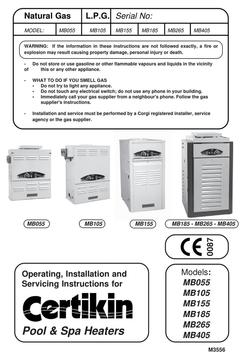
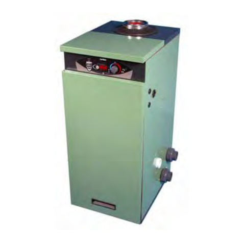
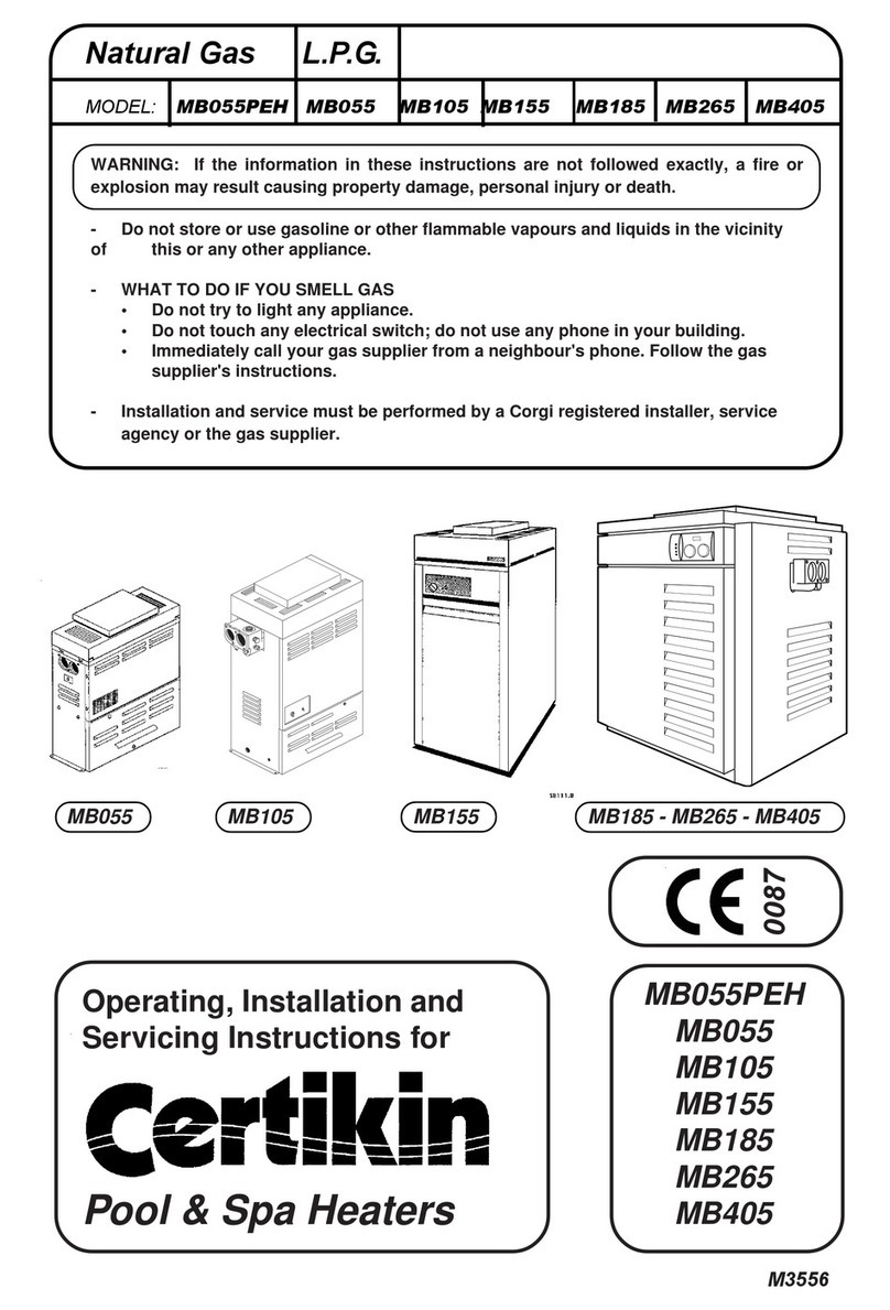
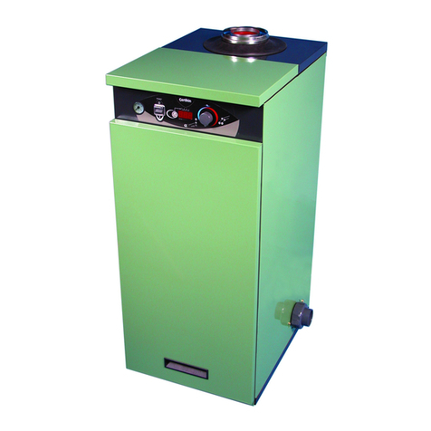
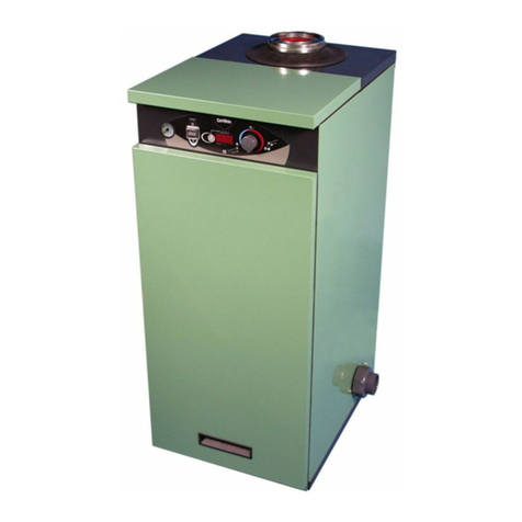
Certikin Genie DUAL MB35D User guide

WARNING: If the information in these instructions are not followed exactly, a fire or explosion
may result causing property damage, personal injury or death.
- Do not store or use gasoline or other flammable vapours and liquids in the vicinity
of this or any other appliance.
- WHAT TO DO IF YOU SMELL GAS
• Do not try to light any appliance.
• Do not touch any electrical switch; do not use any phone in your building.
• Immediately call your gas supplier from a neighbour's phone. Follow the gas
supplier's instructions.
- Installation and service must be performed by a Gas Safe registered installer. A page is
included on the inside back page of this booklet for recording commissioning and
service details.
Operating, Installation and
Servicing Instructions for
Condensing
Pool & Spa Heaters
M2709
Model:
MB36D
Genie DUAL
Serial No:
Factory set for Natural Gas.
Can be Converted to Propane
withpartsprovided.
GB, IE, CH, ES, PT,
SI, SK & TR
0087

PERFORMANCE SPECIFICATIONS
GASCATEGORY,TYPEANDSUPPLYPRESSURE II2H3P G20 @ 20 mbar
G31 @ 37 mbar
NATURAL GAS PROPANE
MODEL MB35D MB35D
Corgi Work Code 1036909 1036913
HEAT GROSS kW 38.0 38.0
INPUT Btu/h 129,650 129,650
NET kW 34.2 35.0
Btu/h 116,700 119,400
TYPICALEFFICIENCY %gross 92 - 94 92 - 94
%net 102-104 102-104
POOL kW 35.7 35.7
OUTPUT Btu/h 121,870 121,870
HEATING kW 6 - 15.6 6 - 15.6
OUTPUTRANGE Btu/h 20,500 - 53,250 20,500 - 53,250
GASRATE (NG, Propane) m3/h 3.45 1.43
MAXIMUMRATE, CO 120-150 130-160
COMBUSTIONSETTINGS,NG, CO29.2-9.4 10.3-10.5
OFFSETSETTING pA -3.0 -3.0
ORIFICE mm Notrequired 4.4
GENERAL SPECIFICATIONS
WATERCONTENT 4.0 Litres 0.88gallons
WEIGHT (net) 54 kg 119lbs
DIMENSIONS,OVERALL 375 mm wide, 520 mm deep, 1040 mm high
SERVICECLEARANCE 300mmLeft,RightandAbove.800 mmInfront
COREDRILLDIAMETER 175 mm
MINIMUMFLOWRATE 80 l/m (17.8 gpm)
MAXPRIMARYWATERPRESSURE 2½bar (37 psi)
INTERNALPUMPSETTING Speed 3
MAXIMUMPOOL TEMP Pool 41°C(106°F)
ELECTRICALSUPPLY 230V 50Hz, FUSED AT 3A, 130W
PROTECTIONLEVEL IP44
FLUESYSTEM 80/125 PP, to a maximum Flue Equivalent Length of 20m
Condensing Pool Heater 01/07/09
TECHNICAL DATA
GB,IE,PT,CH,ES,PT,SI,SK,TR

TECHNICAL DATA Inside cover
User Instructions 1
INTRODUCTION 3
Heater Location 3
Gas Supply 4
Conversion 4
Flueing 4
Air Supply 4
Outdoor Heaters 4
Condensate Drain 5
Pool Pump & Pipework 5
Winterisation 6
Hydraulic Designs 6
Electricity Supply 6
INSTALLATION OF HEATER 7
Procedure 7
Outdoor Terminal 7
Flue Systems 7
Wall Terminal 7
Flue Examples 10
Roof Terminal 12
Pool Plumbing 12
Pressure Switch 12
Gas Conversion 13
Gas Connection 13
Condensate Connection 14
Electrical Connection 14
Commissioning 16
Control Setup 17
Multiple Heater Kit 18
Wall Mounting Kit 20
FAULT FINDING 23
Operation 23
Safety Controls & Lockouts 23
Engineering Mode 23
Test Temperature Disp.Mode 23
Display Fault Codes 24/25
SERVICING 26
Routine Service 26
Changing Components 26
Spares 29
Heater Components 30
COMMISSIONING & SERVICE
HISTORY Inside back cover
List of Figures Page
Fig 1.0 Terminal Positions 4
Fig 2.0 Hydraulic Resistance Graph 5
Fig 2.1 Hydraulic Schematic 6
Fig 2.2 Heating Design Examples 6
Fig 3.0 Outdoor Terminal Fixing 7
Fig 3.1 Service Access &
Pipe Connections 8
Fig 3.2 Wall Terminal Dimensions 8
Fig 3.3 Outdoor Terminal Dimensions 9
Fig 3.4 Roof Terminal Dimensions 9
Fig 4.0 Wall Terminal Installation 10
Fig 4.1 Extended Wall Terminal
Installation 10
Fig 4.2 Extended Vertical Roof
Installation 10
Fig 4.3 Outdoor Terminal Installation 10
Fig 5.0 Pressure Switch 12
Fig 6.0 Throttle Adjustment 13
Fig 6.1 Orifice Position 13
Fig 6.2 Gas Valve Tappings 13
Fig 7.0 Condensate Disposal 15
Fig 7.1 Condensate Syphon 15
Fig 8.0 Heat Exchanger Air Vent 16
Fig 8.1 Pump Priming 16
Fig 8.2 Heat Exchanger Sight Glass 17
Fig 8.2 Heating Output setting 17
Fig 9.0 Controls 17
Fig 10.0 Multiple Heater Install 18
Fig 10.1 Multiple Heater Install 18
Fig 10.2 Multiple Heater Install 20
Fig 10.3 Wall Mounted Heater 20
Fig 10.4 Wall Mounting Dimensions 20
Fig 10.5 Wall Mounting Assembly 21
Fig 11.0 Schematic Wiring 22
Fig 12.0 Electrode gap setting 26
Fig 13.0 Electrical Components 29
Fig 14.0 Heater Components 30
Section Page
Contents
Condensing Pool Heater 01/07/09

Before Start Up
Keep heater area clear and free from combustibles,
flammable liquids and chemicals.
PoolwatermustbeflowingthroughtheHeaterand the
Heaterpressuregaugeshowingbetween1.5to2.5bar
for it to operate.
Quick Start
Check that the Electricity and Gas Supplies are on.
Turn on the Pool Pump. Turn on the Heater with the
Pool or Heating Temperature Knob and set the
desired temperature. In a few seconds the Heater
will fire.
Summary of Controls (Left to Right)
Lock/Reset Button - If it is pressed for 2 seconds
it locks the Set Temperature so the Pool Tempera-
ture Knob is inoperative. To unlock, press again for 2
seconds. When locked a short press or turning the
Temperature Knob flashes the set temperature.
It also resets Gas Control lockouts, GAS and OH2.
Pool Temperature Control Knob
16°C to 32°C (60°F to 90°F)
(Maximum is changed in Setup Mode, see Page 16)
Rotate clockwise to increase the Pool Temperature.
The Setting Temperature is shown whilst rotating
and for 3 seconds after.
To lock the required Temperature Setting see
Lock/Reset Button.
Pool Demand LED - Green
Off - There is no Pool Heating demand, pool heating
is off.
On - There is Pool Heating Demand and the Pool is
not up to temperature.
Flashing - The Pool Heating Demand is met, the
pool is up to temperature.
Temperature Display -
In Pool Heating Mode.
This normally shows the Pool Temperature but also
shows the Setting Temperature when the Pool
Temperature Control Knob is moved.
Condensing Pool Heater 101/07/09
Genie
Dual
USER'S OPERATING INSTRUCTIONS
FOR YOUR SAFETY - READ BEFORE OPERATING
WARNING: IF YOU DO NOT FOLLOW THESE INSTRUCTIONS EXACTLY, A FIRE OR EXPLOSION
MAY RESULT, CAUSING PROPERTY DAMAGE, PERSONAL INJURY OR LOSS OF LIFE.
This appliance is equipped with an ignition device
which automatically lights the burner.
BEFORE OPERATING after a prolonged time off,
smell all around the appliance area for gas. Be
sure to smell next to the floor because some gas
is heavier than air and will settle on the floor.
WHAT TO DO IF YOU SMELL GAS
* Do not try to light any appliance
* Do not touch any electric switch
* Do not use any phone in your building.
* Immediately call your gas supplier
from a neighbour's phone. Follow the
gas supplier's instructions.
* If you cannot reach your gas supplier,
call the fire service.
* Isolate the appliance with the Service
Cock inside. If this is not accessible,
isolate at the gas meter.
* Do not use this appliance if any part has been
under water. Immediately call a qualified
service engineer to inspect the appliance and
to replace any part of the control system and
any gas control which has been damaged.
CAUTION: Propane gas is heavier than air and
will settle on the ground. Since it can accumulate
in confined areas, extra care should be exercised
when lighting Propane heaters.
WARNING: There are no user servicable items in
thisappliance.Donotinterferewithany sealed
components.
MPORTANT INFORMATION
Incorrect water balance will cause premature
failure of this heater. Such damage is not covered
under warranty. For additional information please
see page 3 of these Instructions.
Reset/Lock
Button Temperature
Display
Pool Temperature
Control Knob Pressure
Gauge
Heating Temperature
Control Knob

Condensing Pool Heater 201/07/09
In Heating Mode.
It normally shows the boiler temperature but also
shows the Setting Temperature when the Heating
Temperature Knob is adjusted.
If the display alternates a temperature with ‘SEr’ it is
recommended that the Heater is serviced, it will
continue to function.
The Display is also used for commissioning and
diagnosticpurposes. (Page 16)
Heating Demand LED - GREEN
(Only in use when heating system connected)
Off - There is no Heating Demand , heating is
switched off.
On - There is a Heating Demand , heating is on but
not yet up to temperature.
Flashing - The Heating Demand is met , heating is
up to temperature.
Heating Temperature Control Knob
(Onlyusedwhenheating system connected)
Off - There is no Heating Demand, heating is
switched off.
Normal - Normal setting for heating, it can be
adjusted lower if required.
(NOTE: The Heater is supplied set for Pool Priority.
It will satisfy the Pool Temperature before providing
Heating. To change the priority, see Page 16,
Commissioning Section, of these Instructions)
Pool Pump Pressure LED - YELLOW
On - If the pump is running there is insufficient
pressure, possibly due to a blocked Pool Filter. The
Heater will not run.
Lockout - Left Red LED, Display “GAS”
On - This indicates the Heater Gas Ignition Control
has locked out. Press the Lock/Reset Button to start
the Heater again. If this problem persists this should
be investigated by a Service Engineer.
Condensate - Right Red LED, Display “HI”
This indicates that the Condensate drain is blocked
and the Heater has shutdown. When the blockage is
cleared for the Heater will operate again.
Overheat - Flashing Red LED, Display “OH2”
Flashing - This indicates the Heater has overheated
and it has shutdown. Wait for the Heater to cool then
press the Lock/Reset Button to start the Heater
again. If this problem persists this should be investi-
gated by a Service Engineer.
Pressure Gauge - This should be between 1.5 to
2.5 bar, repressurise if too low.
General Information
Water Pressure Switch
A pool water pressure switch is provided in the
heater to shut off the burners in the event that water
supply to the heater is interrupted. The water
pressure switch should be checked and adjusted for
proper operation by a qualified service person at the
time of installation, and thereafter checked at each
service.
WARNING: Operation of the heater without water
circulation will cause rapid and severe damage to
the Heater.
Water Temperature Settings
The Heater is designed to provide the maximum
amount of heat to the pool up to one degree below
the set temperature. For that last degree it reduces
the power to maximise control. For certain installa-
tion designs, if the pool is used before it is up to set
temperature, the water entering the pool from the
Heater could be warmer than the pool. This is not a
fault but part of the design. It will reduce for the final
degree up to set temperature.
Chemistry
Please see page 3 for the maximum levels and the
proceduralrequirementsforaddingchemicals
Cleaning
It is recommended that periodically the casing is
cleaned and sprayed with WD40 or similar liquid, and
any exposed threads are lightly coated in grease.
Service & Maintenance
It is recommended that the Heater is serviced every
2000 hours of operation, for normal use this is about
12 months. The control will alert when you when it
reaches this period by its display, ‘SEr’ alternating
with the temperature.
It is a mandatory requirement that any gas work
carried out must be by a registered engineer with an
appropriate accreditation.
Winterisation
Provided the Mains Electricity and Gas are con-
nected and on, the Heater will fire to prevent it
freezing, it will use the space heating circuit for this.
If the Pool and Heater are not going to be used for
the cold winter months it is recommended that the
equipment is winterised. Contact your pool installer
for help with this.
Failure to run or winterise the Heater during a period
of freezing could cause damage to the Heater which
will not be covered by your warranty.

Water Undertaking, any relevant requirements of the
Local Authority, and Health and Safety document No
635, “Electricity at at Work Regulations”. Detailed
recommendations are contained in the following
British Standard Codes of Practice.
Codes of Practice.
BS.6798 Installation of gas fired hot water boilers of
rated input not exceeding 70kW.
BS.5440: Part1 and Part 2. Flues (for gas appli-
ances of rated input not exceeding 60kW).
BS 6891 Specification for installation of low pressure
gas pipework.
BS5482:1 Code of practice for domestic butane &
propane gas burning installations.
Building Regulations Part L1.
IMPORTANT.It is important that no external
control devices are directly connected to this appli-
ance - unless covered by these ‘Installation and
Servicing Instructions’ or otherwise recommended
by the manufacturer. If in doubt, please enquire.
Any direct connection of a control device not
recommended by the manufacturer could infringe
the Gas Safety (Installation & Use) Regulations, the
above regulations and the normal appliance war-
ranty.
Manufacturer’s notes must NOT be taken, in any
way, as overriding statutory obligations.
Location of Heater
The Heater MUST be installed on a flat and level
floor or wall, capable of adequately supporting the
weight of the Heater and any ancillary equipment.
Provisionis provided fortheheater to befixed to the
floorand a kitis available forwallmounting.
It is IP 44 Rated and can be installed outdoors in a
suitable position. In all cases the choice of position
should take into account the flue, the plume and
condensate drainage.
IMPORTANT NOTICE.
If the Heater is to be fitted in a timber framed build-
ing it should be fitted in accordance with the British
Gas publication ‘Guide for Gas Installations in
Timber Frame Housing’, reference DM2. If in doubt,
advice must be sought from the Local Gas Region of
British Gas.
The Heater may be installed in any room or internal
space. Particular attention is drawn to the require-
ments of the current I.E.E Wiring regulations and, in
Scotland, the electrical provisions of the Building
Regulations applicable to Scotland with respect to
the installation of the boiler in a room or internal
space containing a bath or shower.
Condensing Pool Heater 301/07/09
TheseInstructionscover an indirect, floormounted,
gas fired, condensing pool and space heater which
is room sealed and fan assisted. The flue system
available is concentric, left, right, rear, and vertical,
all up to 20 metres ‘FEL’. There is also an Outdoor
Top terminal for use where the Heater is installed
out of doors. The ignition system is fully automatic.
The Heater is designed to also provide a heating
output suitable for a number of radiators or an
indirect Hot Water cylinder.
There is one model - see the Technical Data on
Inside Cover for details. The Heater can be in-
stalled in multiples to obtain a larger, combined
output.
The casing is of green and black polyester powder
coated mild steel. The Heater uses a high perform-
ance stainless steel heat exchanger and is suitable
for connection to pools using chlorinated and salt
chorinated water provided the following levels of
chemicals are maintained.
pH 7.2 to 7.8
Total Alkalinity 80 to 140 ppm
Calcium Hardness 200 to 400 ppm
Salt maximum 30000 ppm
Free Chlorine 1 to 4 ppm
All chemicals must be introduced and completely
dilutedintothepoolwaterbeforebeingcirculated
throughafiring heater. Do notplacechlorinetablets
or bromine sticks in the skimmer, high chemical
concentrations will result when the pump is not
running.TurntheHeateroffwhenshockdosing
Chlorinators must feed downstream of the heater
and have an anti-siphoning device to prevent
chemical back-up into the heater when the pump is
shut off.
NOTE: High chemical concentrates from feeders
and chlorinators that are out of adjustment will
cause corrosion to the heat exchanger in the
heater. Such damage is not covered under the
warranty.
Gas Safety (Installation and Use)
Regulations, (as amended).
It is the law that all gas appliances are installed by a
competent person (e.g. a Gas Safe registered
operative) in accordance with the above Regula-
tions. Failure to install appliances correctly could
lead to prosecution. It is in your own interest, and
that of safety, to ensure that the law is complied
with.
The installation of the Heater MUST also be in
accordance with the current I.E.E. Wiring Regula-
tions, the Local Building Regulations, Building
Standards (Scotland), the Bye Laws of the Local
INTRODUCTION
Condensing Pool Heater 401/07/09
Where a room sealed appliance is installed in a
room containing a bath or shower then the appliance
and any electrical switch or appliance control,
utilising mains electricity should be so situated that it
cannot be touched by a person using the bath or
shower.
Where the installation will be in an unusual location
then special procedures may be necessary and
BS6798 gives detailed guidance on this aspect.
A compartment used to enclose the Heater MUST
be designed and constructed specially for this
purpose. An existing cupboard, or compartment,
may be used provided if it is modified for the pur-
pose. Details of essential features of cupboard
compartment design, including airing cupboard
installations are given in BS 6798.
In siting the Heater, the following limitations MUST
be observed:
1. The position selected for installation MUST allow
adequate space for servicing in front of the boiler
and for air circulation around the boiler.
2. This position MUST also permit the provision of a
satisfactory balanced flue termination.
3. This position MUST also permit the provision of a
satisfactory connection to the condensate drain.
Gas Supply
An existing meter and pipework should be checked,
preferably by the Gas Supplier, to ensure that they
are adequate to deal with the rate of gas supply
required.
Supply pipes should be sized to suit the installation
and obtain a working pressure of 20 mbar (NG), 37
mbar (Propane) 29 mbar (Butane). Installation pipes
should be fitted in accordance with BS 6891.
A Natural Gas Heater must be connected to a
governed meter.
Conversion
For countries permitted to use different gasses the
appliance is supplied setup for the primary gas. It
can be converted to an alternative by the addition of
an Orifice which is supplied with the heater. See the
insidecoverpageforthe data and Page13forconver-
sion instructions.
Flueing
Only flue components specified by the Manufacturer
should be used with these appliances. Detailed
recommendations for flueing are given in BS 5440:
The following notes are intended for general guid-
ance.
1. Be aware of the plume from the flue and the
wetting effect it can have to adjacent property.
2. The flue can be taken upwards, left, right or to
the rear of the appliance, but never downwards.
Fig. 1.0
3. The Heater is supplied separate to the chosen
flue set. It can be fitted with up to 20 metres
equivalentlengthof Concentric flue,seethe Flue
Section on page 9, 10 & 11 for examples and
parts selection.
IMPORTANT.
It is absolutely ESSENTIAL to ensure in practice,
that products of combustion discharging from the
terminal cannot re-enter the building, or any other
adjacent building, through ventilators, windows,
doors, other sources of natural air infiltration or
forced ventilation/air conditioning.
If this should occur, the appliance MUST be turned
OFF IMMEDIATELY and the Local Supplier con-
sulted.
Air Supply
It is NOT necessary to have a purpose provided air
vent in the room or internal space in which the boiler
is installed.
Where the boiler is installed in a cupboard or
compartment no air vents are required.
However the user may wish to ensure that it is
ventilated to provide air circulation.
Outdoor Heaters
These Heaters are certified for outdoor installation,
when equipped with the approved terminal.
WARNING:Theheatershallnotbelocatedinanarea
where water sprinklers, or other devices, may cause
water to spray through the cabinet openings and into
the heater. This could cause heavy internal rusting or
damage some electrical components, and this would
void the warranty.
It is recommended that periodically the casing is
cleaned and sprayed with WD40 or similar liquid, and
any exposed threads are lightly coated in grease.
Terminal Position Minimum
Below window or vent 300 mm
Below gutter or pipes 75 mm
Below eaves 200 mm
Below balcony or roof 200 mm
From a window 200 mm
From vertical pipe 75 mm
From corners 300 mm
Above ground, roof or balcony 300 mm
From facing surface 600 mm
From facing terminal 1200 mm
From opening under a car port 1200 mm
Vertically from a terminal 1500 mm
Horizontally from a terminal 300 mm

Genie Resistance
0.0
0.2
0.4
0.6
0.8
1.0
1.2
1.4
1.6
0 50 100 150 200 250
l/m
m head
Space Heating
It is essential that an additional expansion vessel
is sized and fitted to the enlarged system. The
one provided is 4 litres.
This appliance is designed to provide a heating
output and this can be plumbed into the flow and
return connections on the left hand side of the
Heater.
The pump in the Heater is able to provide the circula-
tion required for all types of ‘heating’ circuit, radia-
tors, cylinders and fan coil units. The Heater also
includes an electric 3 port valve which determines
the flow of the heated water. (See Fig 2.1)
The Heater’s control enables a priority to be selected
(See Commissioning page 17), Pool satisfied
before Heating or vice versa. The Heating tempera-
ture control on the front panel enables the maximum
flow temperature to be set.
The heating system should be installed in accord-
ance with current good practice, three example
designs are given in Fig 2.2
The control will automatically reduce the output for
Heating to about 15% (~6kW). If this is insufficient it
can be increased in Service Mode
(See Fig 8.3 and Commissioning page 16 and
Fault Finding on page 23)
Condensing Pool Heater 501/07/09
Condensate Drain
See Fig. 7.0, and 7.1
A 75mm condensate trap is provided in the Heater
and is satisfactory when connected to Soakaways,
Gullies, Rainwater Pipework and Internal Drainage
systems. All pipework and fittings in the condensate
drainage system MUST be made of plastic, unless
they carry other liquid waste. No other materials
may be used. The pipework should be insulated if
run out of doors.
The drain outlet on the boiler is :
40 mm Hunter waste pipe.
Pool Pump & Pipework
The Heater is an indirect design and uses two very
high performance heat exchangers. The pool water
passes through the Secondary, the water in the
Primaryis completely separate.The Heater controls
modulate the input when approaching the set tem-
perature for greater accuracy and economy. It is
recommended that pool pump overrun is used to
maximise the life of the Heater.
If a new pump is being fitted consult the Pressure
Loss graph (Fig 2.0) to determine its size.
The Heater is provided with both 1½” and 50mm
plastic pool connections. As built the connections are
‘From Pool’ on the left, ‘To Pool’ on the right, how-
ever these can be easily reversed.
With the exception of automatic dosing equipment,
the Heater should be plumbed as the last piece of
equipment before the pool.
It is permissable to fit an isolating valves on the
pipework on either side of the Heater but in these
circumstances it is recommended to fit a flow switch
in the Heaters Mains supply.
Fig. 2.0

Primary
TH flow
TH exch
Flow Stat ~ 80C
Hi Limit Stat ~ 100C Manual Reset
Expansion Vessel
Flue High Limit ~ 100C Manual
P
Tf
Tf
T lim T lim
Exp V Exp V
2 x NRV
D
Drain
D
Water 2 Water
Th pool
TH exch
TH flow
TH pool Pool Sensor
Heat Exchanger Sensor
Flow Sensor
230609
PPressure Switch
Rear connection
PRV
PRV
G
GPressure Relief Valve
Pressure Gauge
External circuit
3P
3P 3 Port Valve
Tf lim
Tf lim
Hydraulic Schematic
Condensing Pool Heater 612/08/09
Fig. 2.2
Heater
Secondwater2water
heatexchanger
withAquastatorsimilar
Pool Plus Heating and Hot Water Pool Plus Heating
PoolPlusSpa
3 Way Valve
Expansion vessel
Heater Expansion
Vessel
4 litres
Heater
Expansion vessel
Heater Expansion
Vessel
4 litres
Heater
Heater Expansion
Vessel
4 litres
Winterisation
Leave the Mains Electricty and Gas Supply on and
the Heater will run its own Frost protection pro-
gramme using the Space Heating circuit. This can not
be used if the heating circuit has not been completed.
If the pool is not being heated disconnect heater from
mains elecricity.
Alternativelythe Heater andHeatingcircuit canbe
drained by fitting the drain assembly in place of the
double check valve/hose connector. The Condensate
Syphon can be drained by removal of its Drain Cap.
See Fig 7.1
Electricity Supply
Wiring external to the appliance MUST be in accord-
ance with the current I.E.E. Wiring Regulations and
any Local Regulations that apply.
Fig. 2.3
TheHeater operate with230V~ 50Hz.Singlephase.
Fuse rating is 3A.
The method of connection to the mains electricity
supply MUST facilitate complete electrical isolation
of the Heater, preferably by the use of a fused
double pole switch having a 3mm (1/8in.) contact
separation in both poles and servicing only the
Heater and its controls.
The point of connection to the mains should be
readily accessible and adjacent to the Heater.
Note. Where a Heater is installed in a room con-
taining a pool or shower, the appliance, any electri-
cal switch or appliance control utilising mains elec-
tricity should be so situated that it cannot be
touched.
Example Heating Designs

Suggested procedure:
Site to suit the pool, terminal, plume and condensate
drain limitations. The Terminal position should follow
BS 5440 and be at least 600mm away from any
opening or obstacle.
1. For an indoor installation only : Mark & Drill
Flue hole. (See Fig. 3.1 and 3.2 for dimensions)
2. Fix the Heater to the floor using the holes pro-
vided in the front channel. See page 20 for the
wall mounting details.
3. The Heater should be connected to a suitable
supply as detailed on Page 6. It is required to
providebothpermanentandSwitchedlive supplies
to the Heater, this can be achieved as follows:
Remove Front Top Panel after releasing the
retaining M5 screw under the lip.
Remove the Electrical Cover to access the
Mains connector.
Pull out the Mains connector and replace
the link wire with a Permanent and Switched
live supply. (See Fig 11.0)
4. Pipe to the 22mm gas connection. A gas isolating
valve is provided on the Heater Gas Valve.
5. Plumb to the Pool Pump and Filter.
6. Fill Primary system with water using the supplied
hose connector. The Heater is supplied with one
litre of Sentinel X100 Inhibitor in the pipework.
IMPORTANT. Remove the air from the primary
through the Air Vent on the righthand Side Panel
and the Vent on the top of the Primary Heat
Exchanger. (See Fig 8.0) by running the internal
pump in short one second bursts, venting, then
pumping, until it has all been removed. The pump
can be run by rotating the Pool Thermostat to
show ‘P’ on the display, this also energises the 3
Port Valve to include the Heating circuit. The
Mains must be connected and on.
7. Test for leaks.
8. Replace the Electrical Cover and Panels.
Assembly of the Outdoor Terminal
A specific Outdoor Top Terminal must be used for an
outdoor installation. There must be at least 600mm
clearance around the terminal and complete clear-
ance above. The Outdoor Top Terminal is a push fit
into the Flue Adapter and locked in position with a
clamping ring. (See Fig. 3.0 & 3.3)
If lubrication is required only Centra Cerin or silicone
grease should be used.
All Other Flue Systems
ThemaximumFlueEquivalent Length (FEL) permitted
is20 metres, horizontalor vertical. Thecomponent
partshavethe following FELs:
Condensing Pool Heater 701/07/09
1 metre of concentric flue 1.0
2 metres of concentric flue 2.0
A 45 degree concentric bend 1.1
A 90 degree concentric bend 1.5
A concentric Roof Terminal 3.3
A concentric Wall Terminal 3.9
Sumthe FlueEquivalent Lengths usedin thedesign
this must not exceed 20 metres.
All items assemble by a push fit/clamp system. If it is
required to lubricate the seals only Centra Cerin
supplied by the manufacturer or Silicone Grease
should be used. The pipes should be assembled so
the socket end is always furthest from the Heater.
Flues should be supported by brackets every metre
of run. Horizontal flues should incline back to the
Heater by 3 degrees (5mm in 100mm)
Wall Terminal
The Horizontal Wall Terminal is supplied with two
rubber wallplates, one for inside and one for the
outside. The core drill diameter required is 175mm
and should incline upwards to the outside.
Because of the incline the height of the centre of the
flue hole on the wall is determined by the distance of
the heater is from it, calculate as follows.
1. Ensure service clearance is available.
2. Fit the 90 degree elbow to the heater and
measure from its outlet face to the wall.
3. Add 5 mm for every 100 mm distance.
Example: Distance measured = 480 mm
(5 x 480) / 100 = 25 mm
Flue centre 1065 + 25 = 1090mm
If it is required to reduce the length of the Terminal
the minimum overall length is 300mm. The Flue duct
should be cut 10mm longer than the Air duct.
Terminal Guard
The flue products from this appliance are very low
temperature so a guard is only required if the termi-
nal is is in a position where it may be damaged. A
suitable guard is available from:
TFC Ltd. 01732 351555, Model DK6
Fig. 3.0
INSTALLATION OF HEATER
Space Required for Installation and Service.
Left, Right or Above 300 mm 12 in.
In Front 800 mm 40 in.

Heater Dimensions
Pipe Connections
& Locations
Condensing Pool Heater 830/03/10
B
D
Connections
AMultiHeaterConnection
BElectric& External Control(CCP01)
CCHFlow-22mm Copper
DGasSupply - 22mmCopper
ESafetyValveOutlet-15mm Copper
FCHReturn-22mmCopper
GCondensateDrain - 1¼”or40mm Hunter Plastic
HFrom Pool - 1½” / 50 mm Plastic Demountable Fittings
Service Access
Left, Right or Above 300mm
In Front 800mm
Rear Flue Left/Right Flue
Horizontal Wall Terminal
Dimensions
Horizontal Wall Terminal
(MBHT)
E
G
H
F
Fig. 3.1
Fig. 3.2
A
C
1133
1133
52mm
1000mm
3°
SW WT
WT 136 188
93°
93°
78 90
841
1008
1048
374
134
533
361
307
233
200
138
409
491
293403
253 (LH)
265 (RH)

Outdoor Terminal
Dimensions
Condensing Pool Heater 901/70/09
Fig. 3.3
Outdoor Flue Terminal
(MBOT)
Fig. 3.4
Clamp Assembly Screw
Pitched Roof
Installation
Vertical Roof Terminal
Dimensions Flat Roof
Installation
Use Seldeck Flashing
System for all Roof
Installations
Vertical Roof Terminal
(MBVT)
1 metre Horizontal/
Vertical Extension Pipe
(MBHVE)
45 degree bends
(MB45DB)
550
500
500

Condensing Pool Heater 10 01/07/09
Flue Examples
Flue Kit Part Codes
Type of Flue System
Kit Code Description Outdoor Kit Horizontal Terminal Vertical Terminal
MBHT Horizontal Wall Terminal n/a Yes n/a
MBHVE 1 metre Horizontal/Vertical Extension Pipe n/a Option Option
MBVT Vertical Roof Terminal n/a n/a Yes
MBOT Outdoor Terminal Yes n/a n/a
MB45DB 45 degree bend n/a Option Option
MB90DB 90 degree bend n/a Option n/a
Outdoor Terminal
Extended Horizontal
Wall Terminal Extended Vertical
Roof Terminal
Horizontal Wall Terminal
MBOT
MB90DB
MBHVE
MBHT
(not shown)
TO OFFSET
USE MB45DB
MB90DB
MBHT
(not shown)
MBVT
MBHVE
TO OFFSET
USE MB45DB
Fig.4.3
Fig.4.0
Fig.4.1
Fig.4.2
Determine the type of Flue system you require and
choose from the list of kits available below:

Condensing Pool Heater 11 01/07/09
Flue Kit Part Codes (cont.)
Kit Code Description FEL Photo of Kit
MBHT Horizontal Wall Terminal 3.9m
MBHVE 1 metre Horiz./Vertical Extension Pipe 1.0m
MBVT Vertical Roof Terminal 3.3m
MBOT Outdoor Terminal n/a
MB45DB 45degreebends(pair) 1.1m
MB90DB 90degreebend 1.5m
Flue
Equivalent
Length (m)
The Maximum Flue Equivalent Length (FEL) permitted is 20 metres, horizontal or vertical. The Flue Kits avail-
able below list the FEL for each component. Add up all the FEL’s used in your design and check that this does
not exceed 20 metres. (See page 7)
(per bend)

Condensing Pool Heater 12 01/07/09
Roof Terminal
The Vertical Roof Terminal should be fitted in a
minimum of 300mm clear unobstructed space. It is
not permitted to alter the construction of the Termi-
nal, above the roof line, however the concentric
section below the roof line can be altered to suit the
installation.
It is recommended that:
1. The Installation of the flues are completed before
their connection to the Heater. This will ensure
that any debris that gets into the flues can be
cleared.
2. That bends in vertical flues are 45 degrees.
3. Flues may be reduced in length by cutting. The
inner Flue pipe should be cut so it is 5 to 10mm
longer than the outer Air duct. It will ease assem-
bly if the cut edges are cleaned, chamfered and
greased before assembly.
Pool Plumbing
Theheaterrequireswaterflowandpressuretooperate
properly. It must therefore be installed downstream of
the filter and pump. A typical installation is plumbed as
follows:
1. The Pump outlet is plumbed to the inlet of the Filter.
2. The outlet side of the Filter is then plumbed to the
inlet of the Heater.
3.The outlet of the Heater is plumbed to the return line
to the pool or spa. The Pump, Filter and Heater are
plumbed in series.
If it is necessary to install a valve on the return to the
pool then it is recommended that a flow switch is
installed and interlocked with the Heater supply.
TheHeatermustbelocatedsothatanywaterleakswill
not damage the structure of the adjacent area.
There is no requirement for heat shunt connections to
the Heater, plumbing can be made in standard plastic
1½” or 50mm pipe from the supplied demountables
Use the pressure loss chart on page 5 to select a
suitable pump.
Connection to the Heater can be made from either
left to right, or right to left, it is supplied with the
‘From Pool’ connection on the left. To change, undo
the demount connection on the right, complete with
blanking plates, and swap with the connections on
the left. Ensure that the Pool Sensor is correctly
positioned in its pocket and the Pressure Switch is
connected after the change.
Fig. 5.0
Flow Rate
The Heaters have a very low resistance to the Pool
Water flow and will tolerate a wide range of flows.
The minimum recommended flow is:
80 litres/min
Pressure Switch
The Heater is protected by an adjustable water
pressure switch that has to close before the Heater
will operate.
It is very important to verify that it turns off when
the water flow is interrupted.
It has an adjustment range equivale nt to ±1.5 metres
and is factory set for most conditions but can be
altered if required:
1. With the pump on turn the knurled nut clockwise
until a click is heard.
2. Turn the nut anti-clockwise a quarter of a turn.
3. Turn the pump on and off to check the switch
operates correctly.

Conversion to LPG
The Heater can be converted on site. NG to Pro-
pane, or Propane to Butane.
1. With the Gas and Electrical supply off, undo
the three screws that hold the Venturi to the
Gas Valve. (See Fig.6.0)
2. Allow the Gas valve to drop and gently hang
on its cables.
3. Fit the Conversion Orifice into the Rubber
Seal that sits in the Gas Valve. (See Fig.6.1)
4. Re-assemble the Gas Valve and Venturi.
5. Affix the new Serial Number Data
Label supplied over the existing.
6. Turn Gas on and check for leaks.
7. Fire Heater and allow to run for 5 minutes
before checking and adjusting the CO2 with
the Throttle.(See Fig 6.0 and Datatable
inside cover)
8. Replace the Sealing Cover over the Throttle.
LPG to NG Conversion
The method is as detailed above except the Orifice
is removed and the Venturi and Gas Valve reassem-
bled with just the Rubber Seal between them. A new
Serial Number Data Label should be obtained from
the manufacturer and affixed over the existing.
Gas Connection
The 22mm copper gas connection provided can be
positioned to exit the Heater from either the left or
the right. A minimum of 20mb. (NG), 37mb (propane)
28 mbar (butane) must be available at the Heater
inlet, with the Heater and other connected appli-
ances firing. Check for gas tightness (B.S. 6891:
1988) in pipework to boiler using a manometer.(See
Fig. 6.2) Gas and combustion soundness within the
Heater should be checked using sense of smell and
leak detection fluid. Check the maximum rate and
combustion are to specification.
See Table 6.0 and Datatable Inside Cover.
Condensing Pool Heater 13 01/07/09
Rating Table (1040 Btu/ft³) (38.8 MJ/m³)
kW gross Btu/h sec/ft³m³/2 mins
7.5 25590 145 0.023
12.5 42650 87 0.039
20 68240 55 0.062
34.6 108055 31.5 0.107
52 177420 21 0.161
Table 6.0
Inlet pressure
tapping Offset
connection
Fig. 6.0
Fig. 6.2
Throttle
Adjustment
Fig. 6.1
Orifice in position

Condensing Pool Heater 14 01/07/09
Condensate Connection
The direction of the plastic condensate drain pipe
connection can be altered from the factory position
on the left, to the right.
Remove the blanking plate from the right hand
side (See Fig. 3.1)
Loosen the two screws holding the Trap
bracket and swivel the trap through 90 degrees.
Secure the bracket and fit the supplied 40 mm
pipe.
Example installations are shown in Fig 7.0.
Fit blanking plate to the left hand side.
(See Fig 7.1)
Where possible an internal termination of the con-
densate discharge pipework should be used.
If this is not possible external pipes should be kept
as short as possible and insulated.
Where fitted in pipework that includes another trap or
a pump, for example the filter backwash pipework to
drain, an Air Break should be fitted between the
Heater and that pipework.
Avoid connecting to a kitchen sink trap as the solids
and fats in the drain will cause a blockage.
It is permissible to connect to an external gully or
rain water hopper provided they connect to a com-
bined system.
The condensate should not be run into a ‘grey water’
recycle system.
If the condensate pipe is connected to a stack it
should join not less than 450 mm above the foot of
the stack. In addition it should be positioned so there
no chance of cross-flow to another connection.
Installation pipework must be in 40 mm Hunter
plastic pipe to a suitable drain location with a gradi-
ent of 2.5° (45mm/ metre run) minimum. If connected
to another drainage trap, an air break is required
between the Heater drain and that trap. (See Fig.7.0
& 7.1). External runs, should, if possible, be insu-
lated to defer problems from freezing.
Check during commissioning that there is a leak free
working connection from the Heater to the drain. The
simplest way to do this is to carefully pour some
water into the boiler flue and check it emerges at the
drain. This will also fill the trap ready for operation.
The “Guide to the Condensing Boiler Assesment
Procedure for Dwellings” can be refered to, see
http://www.planningportal.gov.uk/england/profession-
als/en/1115314255842.html
Electrical Connections
WARNING: The appliance MUST be earthed.
All wiring for the Heater and system controls MUST
conform to I.E.E. Wiring Regulations, and work
should be tested using a suitable meter, for Earth
Continuity, Polarity, Short Circuit and Resistance to
Earth.
The Heater supply must be through a common
isolator, a double pole 3A fused isolating switch with
a contact separation of 3mm minimum on both
poles.
The cable used should be no less than 0.75mm2to
BS.6500 PVC, 3 core, and fixed ensuring the Earth
connection is longer than the Live and Neutral.
Access to the Heater connections is made by the
removal of the Front Top Panel and the Electrical
Chassis cover, two screws.
The simplest and most flexible control scheme is to
use a Certikin CCP01 Control Unit. This provides an
electrical safety trip and timer with outputs for the
Heater, lights and an auxilary voltage free output. It
is pre-wired and tested and provided in a standard
IP55 plastic control box.
The Heater’s internal wiring is shown in Fig.11.0.
Connections are as follows :-
4 Way Terminal Supply Connection
Earth
N Mains Neutral
Ls Pool Demand
L Permanent Live
3 Way Terminal
L Heating Demand
It is recommended that this product is supplied with
a permanent live as both the combustion fan and
internal pump require to run after the switched live is
removed.
For systems using an external programmer, the
electrical wiring should follow the relevant control
manufacturer’s recommendations, with the switched
lives from the controls returning to Ls in the 4 and L
in the 3 way push-fit connector.
It is possible to connect several Heaters together
using the Multiple Heater Kit. Details for the parts
and installation of this kit are given on Page 18.

Example Condensate Disposal Methods
Condensate
Drain from
Heater
Condensate Pressure
Switch Pipe
Connection
Connect To
Waste
(Option to
exit Heater
left or right)
Drain Cap, (behind
vessel) can be
removed for
Winterisation
Condensate Syphon (75 mm)
Condensing Pool Heater 15 01/07/09
Fig.7.1
Removable Plate
(Use to close off
unused Waste exit
on panels)
1:20 Fall ( 2.5 Degrees )
Strap-On
Boss
200mm Land Drain
Filled with Lime
chippings 400mm
deep
Insulate against
freezing
Note: Do not reduce the pipe size below the 40mm provided.
Fig.7.0
Soakaway
Stack Attachment
Soil Pipe or
Drain

Condensing Pool Heater 16 12/08/09
Commissioning
General
IMPORTANT The heater primary contains Senti-
nel X100 inhibitor. The minimum water should be
released during filling to maintain its concentra-
tion.
The elimination of air from the heat exchanger is
essential to maximise the life of the Heater.
It is strongly recommended that the Heater is first run
with the GAS OFF until the air has been purged.
If air has not been released then there is a possiblity
of the Heater overheating and triggering one of its
safety thermostats. An Air Vent is provided on the
top of the Heat Exchanger (See Fig 8.0) to assist its
removal. It is opened and closed by rotating the front
connector. A second is a standard radiator vent in
the righthand Side Panel.
The internal pump can be run by using the Pool
Thermostat in the ‘P’ position. (See Fig 8.1) to aid
de-aerating, this also opens the 3 Port Valve to
utilise the heating system. If this is not yet plumbed
andthe connections havebeen sealed, temporarily
remove the brown wire to the 3 Port Valve at its 6 way
terminal strip on the Electrical Chassis. Reconnect
whenre-commissioning withthe heatingcircuit.
It requires that the Mains in connected and that there
is a live on Pool demand, the Pool Pump need not be.
Commissioning - Pool
The Heater Control is factory set to display in Fahren-
heitand workto a maximumtemperature of 90°F
(32°C). If a Centigrade display or higher temperature
106°F(41°C) maximumis required, thiscan be
changedin the UserSetup Mode. (See Page 17)
The boiler is factory set for Natural Gas, fitted with
automatic ignition and will start when the gas cock is
open, mains is connected and the Pressure Switch is
activatedby the poolpump.(for greater detailabout
the internal controls see the Maintenance section,
Fault Diagnosis)
LPG models require to be modified as described on
page 13.
It is recommended that the condensate trap is full of
water before firing.
If the Heater fails to light the gas it will shutdown
and try again. It will repeat this a total of 5 times and
then lock out. This will show as the Red LED lit and
‘GAS’ on the display. Press the Lock/Reset button
to start another 5 attempts.
It is possible with the front door off to see when the
burner is lit through the sight glass. (See Fig. 8.2)
After the burner has been lit for a few minutes the
gas rate and combustion should be checked, see
the Technical Data on Inside Cover for details.
The Heater is factory set and should not require
adjustment. When the Heater has been running for
at least 10 minutes check all joints, gas and water,
for leaks, and correct where necessary.
When running satisfactorily, complete the commis-
sioning details on the inside back page of these
instructions.
Note: The boiler is fitted with a syphon trap that in-
cludesablockeddraindetectiondevice.Thisistosafe-
guardthe boiler fromablockage or thepossible freez-
ing of the condensate pipework in extreme weather.
Should this happen the control will lockout and the
display will show ‘HI’, as in “condensate level is high”.
See the Fault Finding section for more details.
Thiswillhavetobecorrected before the Heater will run.
The user should be made aware of this feature and,
that in the event of blocked or frozen condensate
pipework,theboiler will automatically stopfunctioning.
Itwill start againas soon asthe blockage hascleared.
Finally,instructtheuseronHeatersoperationandcon-
trols.
Commissioning - Heating
First commission the Heater for Pool use.
As supplied the Heater is set to provide its minimum
output to heating, about 6 kW. This can be increased
butnot decreased.
To increase access the controls Service Mode (See
Page 23) and alter the Heating Input Maximum
from its starting point of 0% to the required level.
(See Fig 8.3). It is not recommended that this is
increased above 50% as the Heater operates as
either as a Pool Heater or a Heating boilers, but not
both at the same time.
The priority of Pool or Heating, which is satisfied
first, can be set in Service Mode (See Page 23).
A four minute anti-short cycling delay operates on
the Heating thermostat, it can be reset to zero by
altering the Heating Temperature Control Knob.
Fig. 8.0
Fig. 8.1

Condensing Pool Heater 17 01/07/09
Switch on with the panel switch whilst pressing the Lock/Reset button then release. The control is now in
Setup Mode.
The control can now be altered by rotating the Pool Temperature Control Knob to a certain position and then
pressing the Lock/Reset button, then switching off. (See Fig. 9.0)
Example:
To change from Fahrenheit to Centigrade:
Turn Panel Switch OFF then back ON whilst pressing the Lock/Reset button.
Turn the Pool Temperature Control Knob until the display shows ‘F’.
Press the Lock/Reset button once and the display will show ‘C’.
Switch the Panel Switch OFF then back ON again.
The Control will now display in Centigrade.
Lock/Reset
Button Temperature
Display
Pool Temperature
Control Knob
Fig. 9.0
User Setup Mode Setting Factory Setting Alternative Display Indicator
1 Display units ° F = Fahrenheit ° C = Centigrade ° F or ° C
2 Maximum temperature 32 °C (90 °F) 41 °C ( 106 °F) PL or SPA
3 Priority Pool first Heating first P or H
4 Software Version e.g 017
Pressure
Gauge
Heating Temperature
Control Knob
Fig. 8.3
Fig. 8.2
User Setup Mode
Heating Output
0
10
20
30
40
50
60
5 7 9 1113151719
Output kW
%
Table of contents
Other Certikin Swimming Pool Heater manuals

Certikin
Certikin COH110 User guide

Certikin
Certikin Genie C Installation guide

Certikin
Certikin MB35S User manual

Certikin
Certikin MB055 User manual

Certikin
Certikin MB20S User guide

Certikin
Certikin MBC100N Manual

Certikin
Certikin MB50S User guide

Certikin
Certikin MB35C User manual

Certikin
Certikin MB055PEH User guide
Popular Swimming Pool Heater manuals by other brands

Raypak
Raypak 185A Replacement instructions

Hayward Pool Products
Hayward Pool Products HeatPro HP20654BT Operations & parts manual

Daewoo
Daewoo Sirius DHS-3002F instruction manual

Coates
Coates 12406ST Installation, operation and maintanance

Waterco
Waterco POOL HEAT PUMP User and care guide manual

Blue Wave
Blue Wave FlowXtreme instructions