CH GWH30LB-D3DNA5E User manual

VICTORIA
HIGH-WALL DUCTLESS
AIR CONDITIONING &
HEATING SYSTEM
INSTALLATION MANUAL
Models:
GWH30LB-D3DNA5E(230V)
GWH36LB-D3DNA5E(230V)

GWH30LB-D3DNA5E(230V)
System Includes: GWH30LB-D3DNA5E/I, GWH30LB-D3DNA3E/O
GWH36LB-D3DNA5E(230V)
System Includes: GWH36LB-D3DNA5E/I, GWH36LB-D3DNA3E/O

Indicates a hazardous situation that, if not avoided, will
result in death or serious injury.
Indicates a hazardous situation that, if not avoided, could
result in death or serious injury.
Indicates a hazardous situation that, if not avoided, may
result in minor or moderate injury.
Indicates important but not hazard-related information,
used to indicate risk of property damage.
Indicates a hazard that would be assigned a signal word
WARNING or CAUTION.

CONTENTS
This symbol stands for the items
should be forbidden This symbol stands for the items
should be followed
The figures in this manual may be different with the material objects, please refer
to the material objects for reference.
The physical product may differ from the drawing in this manual for different display.
If there are some differences between them, please refer to the physical product as
the standard.
This appliance is not intended for use by persons (including children) with reduced
physical, sensory ormental capabilities orlack ofexperience and knowledge,
unless they have been given supervisionorinstructionconcerning use ofthe appliance
by a person responsible for their safety.
Children should be supervised to ensure they are away from the appliance.
■
■
Installation service
Notices for installation. .........................................................................1
Installation dimension diagram. .........................................................3
Install indoor unit. ...............................................................................4
Install outdoor unit. .............................................................................6
Check after installation and test operation. .........................................8
Installation and Maintenance of Healthy Filter. ...................................9
■
■
■
■

●
●
●
●
●
●
Installation service- Notices for installation
Important Notices
1. The unit installation work must be done by qualified personnel according to the local rules
and this manual.
Basic Requirements For Installation Position
Install in the following place may cause malfunction. If it is unavoidable contact with
service center please:
Place where strong heat sources, vapors, flammable gas or volatile object are emitted.
Place where high-frequency waves are generated by radio equipment, welders and
medical equipment.
Place where a lot of salinities such as coast exists.
Place where the oil (machine oil) is contained in the air.
Place where a sulfured gas such as the hot spring zones is generated.
Other place with special circumstance.
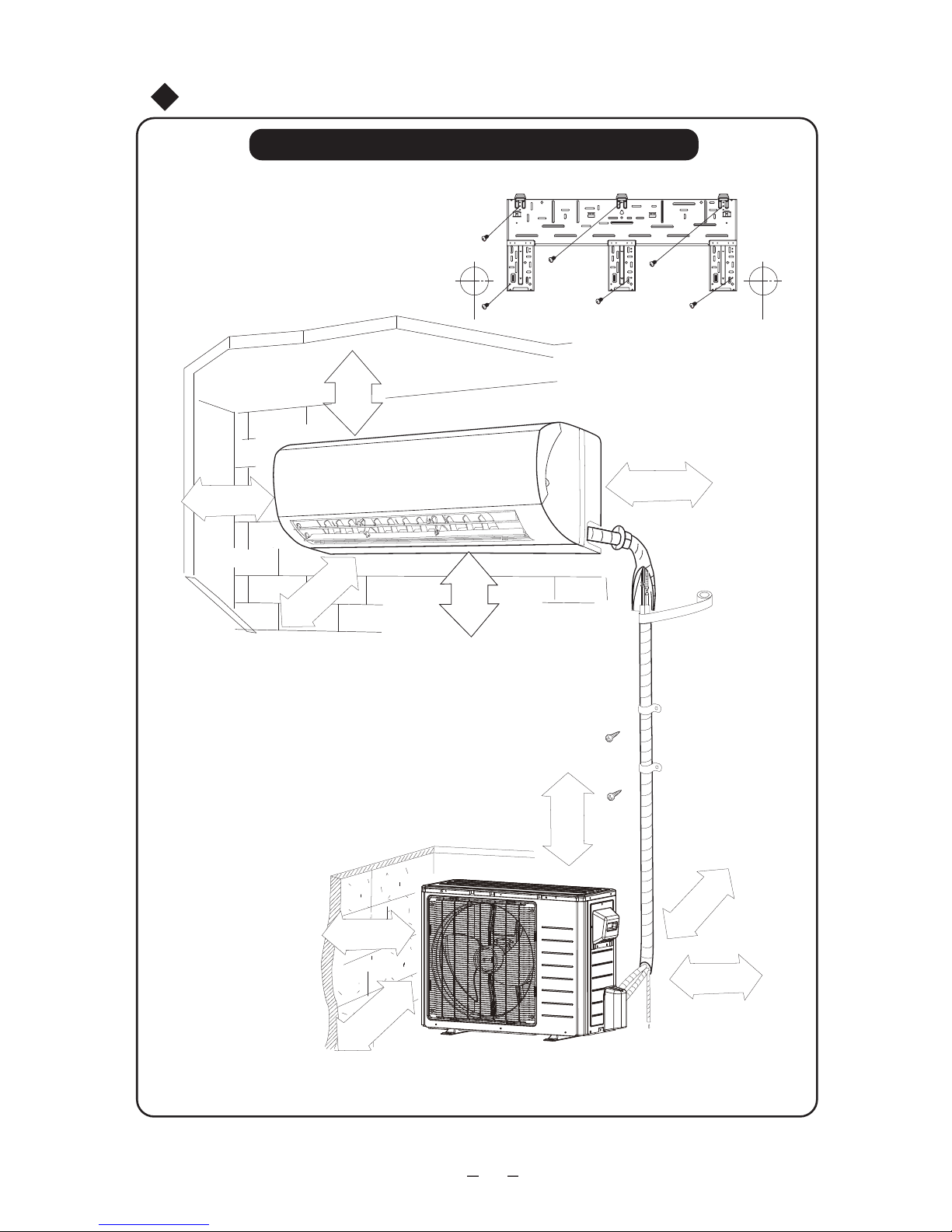
Indoor Unit Installation Position Selection
1. The air inlet and outlet vent should be far from the obstruction, make sure that the air can
be blown through the whole room.
2. Select a position where the condensing water can be easily drained out, and the place is
easily connected for outdoor unit.
3. Select a location where the children can not reach.
4. Can select the place where is strong enough to withstand the full weight and vibration of
the unit. And will not increase the noise.
5. Be sure to leave enough space to allow access for routine maintenance. The height of the
installed location should be 8ft (230cm) or more from the floor.
6. Select a place about 3.28ft (1m) or more away from TVset or any other electric
appliances.
7. Select a place where the filter can be easily taken out.
8. Make sure that the indoor unit installation should accord with installation dimension
diagram requirements.
Outdoor Unit Installation Position Selection
1. Select a location from which noise and outflow air emitted by unit will not inconvenience
neighbors, animals, plants.
2. Select a location where there should be sufficient ventilation.
3. Select a location where there should be no obstructions cover the inlet and outlet vent.
4. The location should be able to withstand the full weight and vibration of the outdoor unit
and permit safe installation.
5. Select a dry place, but do not expose under the direct sunlight or strong wind.
6. Make sure that the outdoor unit installation dimension should accord with installation
dimension diagram, convenient for maintenance, repair.
7. The height difference of connecting the tubing within 16ft (5m), the length of
connecting the tubing within 32ft (10m).
8. Select a place where it is out of reach for the children.
9. Select a place where will not block the passage and do not influence the city appearance.
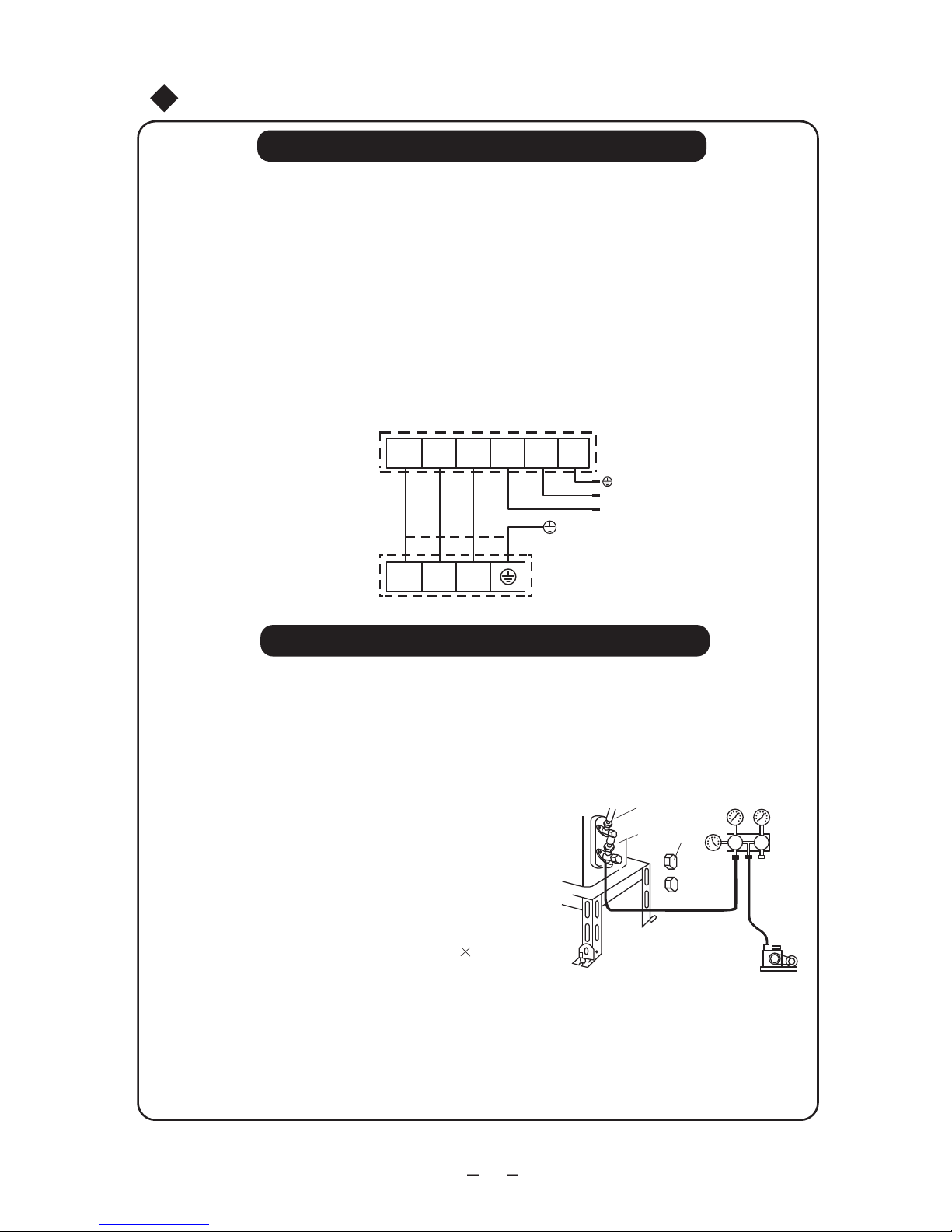
2. If the air conditioner has not plug, directly connect it into the fixed circuit, a breaker should be
installed in the fixed circuit. all pole of this breaker should be switching off and the distance
of the contact should be at least 1/8” (3mm).
1

① ② .
③ ④
3
4.
1.
2.
2
Notices for installation
Earthing requirements
Others
Safety Requirements For Electric Appliances
The connection method of unit and power cable as well as the interconnect method
of each isolated component should refer to the circuit diagram stick on the unit.
The model of the blown fuse and rated value should refer to the silk-screen on the
controller or fuse sleeve.
1. Air conditioner is type I electric appliance, thus please do conduct reliable earthing
measure.
2. The yellow-green two-color wire in air conditioner is earthing wire and cannot be used
for other propose. It cannot be cut off and be fix it by screw, otherwise it would cause
electric shock.
3. The earth resistance should accord to the National Criterion.
4. The user power must offer the reliable earthing terminal. Please don't connect the
earthing wire with the following place:
Tap water pipe.Gas pipe.
Contamination pipe.
Other places that professional personnel consider them unreliable.
Note:
Make sure that the Live wire or Zero line as well as the earth wire in the family power
socket can not be wrong connected, there should be reliable and no short circuit in the
diagram.
wrong connection may cause fire.
The min. distance from the unit and combustive surface is 59in (1.5m).
It should be reliably earthed, and it should be connected to the special earth device,
the installation work should be operated by the professional.
The air switch must have the functions of magnetic tripping and heat tripping, in order
to protect the short circuit and overloading.
1. The power supply should be used the rated voltage and AC exclusive circuit, the power
cable diameter should be satisfied.
Don't drag the power cable emphatically.
●
●
3. The appliance shall be installed in accordance with national wiring regulations.
4. This appliance is not intended for use by persons (including children) with reduced
physical, sensory or mental capabilities, or lack of experience and knowledge, unless
they have been given supervision or instruction concerning use of the appliance by a
person responsible for their safety.
5. Children should be supervised to ensure that they do not play with the appliance.
6. If the supply cord is damaged, it must be replaced by the manufacturer, its service agent
or similarly qualified persons in order to avoid a hazard.
2

Installation dimension diagram
20in(50cm)
Installation dimension diagram
Space to the ceiling
Above
Above
Above
Space to the wall
Space to the wall
Space to the wall
Above
Above
20in(50cm)
0
2 0
6in(15cm)
9.8ft
(3m) 2
6in
(15cm)
Space to the floor
Air outlet side
Space to the obstruction
Air outlet side
Air inlet side
Above
7ft(2m)
12in(30cm)
Above
8.2ft
(2.5m)
Installation dimension diagram
The dimensions of the space necessary for correct
installation of the appliance including the minimum
permissible distances to adjacent structures
●
6in(15cm)
Above
Above
12in(30cm)
Above
3

Install indoor unit
Install the rear panel
1.Always mount the rear panel horizontally. As the water drainage pipe at the left, when adjusting the rear
panel, this side should not be too high; the right side should be slightly high.
2. Fix the rear panel on the selected location
3. Be sure that the rear panel has been
fixed firmly enough to withstand the weight
of an adult of 60kg, furthermore, the weight
should be evenly shared by each screw.
Install the piping hole
1. Make the piping hole in the wall at a slight downward slant to the outdoor
side.
2. Insert the piping-hole sleeve into the hole to prevent the connection
piping and wiring from being damaged when passing through the hole.
Install the water drainage pipe
1. For well draining, the drain hose should be placed at a
downward slant.
2. Do not wrench or bend the drain hose or flood its end
by water.
3. When the long drainage hose passing through indoor,
should wrap the insulation materials.
Wrenched Bent
Flooded
Indoor Outdoor
Wall pipe
Seal pad
Fig.1
(Rear piping hole) (Rear piping hole)
Left Right
Mark on the middle of it Gradienter
Space
to the
wall
6”
(
150mm
)
above
Space
to the
wall
6”
(
150mm
)
above
Wall Wall
Connect indoor and outdoor electric wires
1. Open the front panel upwardly.
2.Screw off the fixing screw of cover plate and screw off cover plate.
3. Put the power connection cable through the back of indoor unit wire hole and take it out.
4. All the wiring should be connected according to the circuit diagram on the unit.
5. Put the power connection cable the section, which with sheath into wire groove, and
cover the cover plate, screw on the fixing screw, tighten the connection wire.
6. Cover the front panel cover.
4

●
●
●
●
●
1.
2.
(N·m)
Ф6
Ф9.52
Ф12
15~20
31~35
50~55
Ф16 60~65
Ф19 70~75
2.
3.
●
1.
Install indoor unit
NOTE:
When connecting the electric wire if the wire length is not enough, please contact with
the authorized service shop to buy a exclusive electric wire that is long enough and the
joint on the wire are not allowed.
The electric wiring must be correctly connected, wrong connection may cause spare parts
malfunction.
Tighten the terminal screw in order to prevent loose.
After tighten the screw, slightly pull the wire and confirm whether is it firm or not.
If the earth wire is wrong connection, that may cause electric shock.
The cover plate must be fixed, and tighten the connection wire, if it is poor installed, that
the dust, moisture may enter in or the connection terminal will be affected by outside force,
and will cause fire or elelctric shock.
Install the indoor unit
The piping can be lead out from right, right rear,
left, left rear.
When routing the piping and wiring from the left
or right side of indoor unit, cut off the tailings
from the chassis in necessary. (show in Fig.2)
(1)Cut off the tailings 1 when routing the wiring only.
(2)Cut off the tailings 1 and tailings 2 when routing
both the wiring and piping.(or 1,2,3)
Take out the piping from body case, wrap the piping
electric wire, water pipe with tape and put them th-
rough the piping hole.(As show in Fig. 3)
Hang the mounting slots of the indoor unit on the
upper tabs of the rear panel and check if it is firm
enough. (As show in Fig.4)
Install the connection pipe
Align the center of the piping flare with the
relevant valve.
Screw in the flare nut by hand and then tighten the nut
with spanner and torque wrench refer to the following.
Tightening torque table:
Hex nut diameter Tightening torque
NOTE: Firstly connect the connection pipe to indoor unit, then to outdoor unit; pay attention
to the piping bending, do not damage the connection pipe; the joint nut couldn't tighten too
much, otherwise it may cause leakage.
Spanner Torque wrench
Indoor unit piping Taper nut Piping
Fig.4
Fixing hook
Mounting
board
Mounting
board
Right Left rear
Left
Right rear
Fig.3
Fig.2
Tailing 3
Tailing 2
Tailing1
Gas side piping
External connection
electric wire
Liquid side
piping
Liquid side
piping
insulation
Finally wrap itWater drainage pipe
with tape
Gas side piping
insulation
●Leakage circuit-breaker and air switch of correct capacity must be installed.
5

6
●
●
Install outdoor unit
Air purging and leakage test
Electric Wiring
1. Disassemble handle of right side plate or front side plate of outdoor unit.
3. Ensure if wire has been xed well.
4. Install handle or front side plate.
NOTE:
Wrong wiring may cause spare parts malfunction.
After the cable xed, make sure there should be a free space between the connection and
xing place on the lead wire.
2. Take o wire clamp, connect and x power connect cord and power cord to terminal of line
bank.Wiring should t that of indoor unit.
●
5
-1.0 10 pa
(-76cmHg).
5
Air purging and leakage test
Liquid pipe
Gas pipe
Valve
cap
Vacuum
gauge
Vacuum pump
Fig.
1. Connect charging hose of manifold valve to charge end of low
pressure valve (both high/low pressure valves must be tightly
shut).
2. Connect joint of charging hose to vacuum pump.
3. Fully open handle of Lo manifold valve.
4. Open the vacuum pump to evacuate. At the beginning, slightly
loosen joint nut of low pressure valve to check if there
is air coming inside. (If noise of vacuum pump has
been changed, the reading of multimeter is 0) Then
tighten the nut.
5. Keep evacuating for more than 15mins and make
sure the reading of multi-meter is
6. Fully open high/low pressure valves.
7. Remove charging hose from charging end of low
pressure valve.
8. Tighten bonnet of low-pressure valve. (As shown in Fig.5)
POWER SUPPLY
Indoor unit connection
2 3 L1
L1
L2
L2N(1)
2 3N(1)
G
Outdoor unit connection

Ø
●
Outdoor condensation drainage (Heat pump type only)
When the unit is heating, the condensing water
and defrosting water can be drained out reliably
through the drain hose.
Installation: Install the outdoor drain elbow in
25 hole on the base plate, and joint the
drain hose to the elbow, so that the wastewater
formed in the outdoor unit can be drained out
to a proper place.
Chasis
Outdoor drain
elbow
Install outdoor unit
Fig.6
Use soap water or leak hunting meter to check whether
the joints is leak.
Indoor unit check point
Outdoor unit check point
Leak hunting
7

Check after installation and test operation
Items to be checked Possible malfunction
Has it been fixed firmly? The unit may drop, shake or emit noise.
Have you done the refrigerant leakage test? It may cause insufficient cooling(heating)
capacity.
Is heat insulation sufficient? It may cause condensation and dripping.
Is water drainage well? It may cause condensation and dripping.
Is the voltage in accordance with the rated
voltage marked on the nameplate? It may cause electric malfunction
or damage the part...
Is the electric wiring and piping
connection installed correctly and securely? It may cause electric malfunction
or damage the part.
Has the unit been connected to a secure
earth connection? It may cause electrical leakage.
Is the power cord specified? It may cause electric malfunction
or damage the part
Is the inlet and outlet been covered? It may cause insufficient cooling(heating)
capacity.
Has the length of connection pipes
and refrigerant capacity been recorded? The refrigerant capacity is not accurate.
Test Operation
1. Before test operation
(1) Do not switch on power before installation isfinished completely.
(2) Electric wiring must be connected correctly and securely.
(3) Cut-off valves of the connection pipes should be opened.
(4) All the impurities such as scraps and thrums must be cleared from the unit.
2. Test operation method
(1) Switch on power, press "ON/OFF" button on the wireless remote control to start the
operation.
(2) Press MODE button, to select the COOL, HEAT, FAN to check whether the operation
is normal or not.
Check after installation
8

Fig. a
1. Forcibly pull the panel for a specific angle
from the two ends of the front panel according
to the arrow direction. Then pull the air filter
2. Mount the healthy filter onto the air filter,(as
shown in Fig.b). If the air filter cannot be in-
stalled, please mount the healthy filter on
3. Mount the air filter properly along the arrow
direction in Fig.d, and then close the panel cover.
ion filter can't be cleaned with water, while active carbon, photocatalyst,
low temperature conversion (LTC) catalyst, formaldehyde eliminator, ca-
The healthy filter commonly has its usage lifetime for one year under
normal condition. As for silver ion filter, it is invalid when its surface becomes
according to the installation instruction. Pay special attention to that silver
Take out the healthy filter before cleaning and reinstall it after cleaning
Installation and Maintenance of Healthy Filter
●
Healthy filter
Air filter
Healthy filter
downwards to remove it. (See Fig.a)
the front case. (as shown in Fig.c).
Fig. b
Fig. c
Fig. d
techin or mite killing filter can, but can't with brush or hard things. Dry it in
the shade or sun after cleaning, but not by wiping.
black (green).
goods, the latter one shall prevail. The quantity of healthy filters shall be
based on the actual delivery.
This supplementary instruction is provided for reference to the unit with
healthy filter. If the graphics provided herein is different from the physical
Installation Instructions
Cleaning and Maintenance
Service Life
9

OWNER'S MANUAL
Split Air Conditioner
GREE AIR CONDITIONERS
Thank you for choosing GREE air conditioner for correct operation, please
it carefully for consultation.
read this owner's manual carefully before operating the unit and keeps
Cooper and Hunter © 2015
For your convenience, please record the model and serial numbers of your new equipment in
the spaces provided. This information, along with the installation data and dealer contact
information, will be helpful should your system require maintenance or service.
www.cooperandhunter.us
PRODUCT &INSTALLATION RECORD
UNIT INFORMATION
Model No.
Serial No.
INSTALLATION INFORMATION
Date Installed:
DEALERSHIP/INSTALLER INFORMATION
Company Name:
Address:
Phone Number:
Technician Name:

66160000086
Add: West Jinji Rd, Qianshan, Zhuhai, Guangdong, China, 519070
MANUFACTURER: GREE ELECTRIC APPLIANCES, INC. OF ZHUHAI
www.cooperandhunter.us
This manual suits for next models
1
Table of contents
Other CH Air Conditioner manuals
Popular Air Conditioner manuals by other brands

Frigidaire
Frigidaire FFRE103WA1 use & care

Honeywell
Honeywell HL10 Series user manual

Frigidaire
Frigidaire FAZ12ES2A installation instructions

Mitsubishi Electric
Mitsubishi Electric PLA-M100EA installation manual

Friedrich
Friedrich WallMaster WS10 Installation and operation manual

Panasonic
Panasonic CS-C18GKV Service manual

EcoNet
EcoNet A2024AJVCA installation instructions

North American
North American INVENTER SPLIT-TYPE ROOM AIR CONDITIONER installation manual

Friedrich
Friedrich CCW06B10B operating instructions

Daikin
Daikin J Series Service manual

Technibel
Technibel MCAV77C5VAB Technical data & service manual

DeLonghi
DeLonghi EX Series Instructions for use