Supplied By www.heating spares.co Tel. 0161 620 6677
2.
INSTALLATION REQUIREMENTS
I I IMinimumspacing
TerminalPosition Farmed I
2.1
Related Documents
The installation of the heater must be in accordance with
the relevant requirements of the GasSafety Regulations
1972, Building Regulations, IEEWiring Regulations and-the
Byelaws of the local water undertaking. It should also be
in accordance with any relevant requirements in British
Standard Codes of Practice. Detailed recommendations
are contained in the following British Standard Codes of
Practice :
BSCP331 : Pt. 3 : 1974., BS5546 : 1979, BS5440 : Pt. 1 :
1978 and BS5440 : Pt. 2 : 1976.
2.2
Location
The location chosen for the heater must permit the pro-
vision of a satisfactory flue termination. The location
must also permit adequate spacefor servicing and air cir-
culation around the heater.
The heater may be installed in any room or internal space
although particular attention is drawn to the require-
ments of the IEEWiring Regulations and, in Scotland, the
electrical provisions of the Building Regulations applicable
in Scotland, with respect to the installation of a heater in
a room or internal spacecontaining a bath or shower.
Where the installation of the heater will be in an unusual
location special procedures may be necessary and BS
5546 gives detailed guidance on this aspect.
A compartment used to enclose the heater must be de-
signed and constructed specifically for this purpose. An
existing cupboard or compartment may be used provided
that it is modified for the purpose.
Details of essential features of cupboard/compartment
design are given in BS5546.
2.3
Gas Supply
An adequate gas meter must be connected to the service
2.5
pipe. Where necessary the local GasRegion of British Gas
will arrange for the existing meter to be ckecked or for a
suitable meter to be installed. On no account must any
work be cerried out on the gas meter other than by the
local Gas Region or their specifically authorised contrac-
tor.
Installation pipes should be fitted in accordance with CP
331 : 3. Pipework from the meter must be of adequate
size. Pipes of a smaller size than the gas connection
should not be used.
The complete installation must be tested for gas sound-
2.6
ness.
2.4
Siting the Flue Terminal
The standard flue set is suitable for walls having a thickn- I
ess of 75 mm (3 ins.)to 355 mm (14 ins.).Other flue op-
tions are available to a maximum of 3 m (13 ft. 2 ins.)to 2-7
specialorder.
Detailed recommandations for flueing are given in BS
5440 : Pt. 1. The following notes are intended to give ge-
neral guidance.
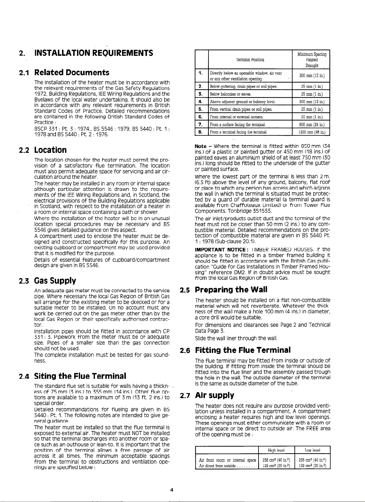
The heater must be installed so that the flue terminal is
exposed to external air. The heater must NOTbe installed
so that the terminal discharges into another room or spa-
ce such as an outhouse or lean-to. It isimportant that the
position of the terminal allows a free passage of air
across it all times. The minimum acceptable spacings
from the terminal to obstructions and ventilation ope-
nings are specified below :
1.
Directlybelowanopenablewindow,airvent
oranyotherventilationopening. 300mm(12in.)
Aboveadjacentgroundorbalconylevel.
Fromverticaldrainuir.xsorsoilDioes.
6. Frominternalorexternalcomers.
7. Fromasurfacefacingtheterminal
8. Fromaterminalfacinatheterminal
25mm(1in)
600mm(24in)
1200mm148in.)
Note
- Where the terminal is fitted within 850 mm (34
ins.)of a plastic or painted gutter or 450 mm (18 ins.)of
painted eaves an aluminium shield of at least 750 mm (30
ins.)long should be fitted to the underside of the gutter
or painted surface.
Where the lowest part of the terminal is less than 2 m.
(6.5ft) above the level of any ground, balcony, flat roof
or placeto which any person hasaccessand which adjoins
the wall in which the terminal is situated must be protec-
ted by a guard of durable material (a terminal guard is
available from Chaffoteaux Limited) or from Tower Flue
Components. Tonbridge 351555.
The air inlet/products outlet duct and the terminal of the
heat must not be closer than 50 mm (2 ins.)to any com-
bustible material. Detailed recommendations on the pro-
tection of combustible material are given in BS 5440 Pt.
1 : 1978 (Sub-clause20.1).
IMPORTANT NOTICE:
TIMBER FRAMEDHOUSES.If the
appliance is to be fitted in a timber framed building it
should be fitted in accordance with the British Gaspubli-
cation “Guide for GasInstallations in Timber Framed Hou-
sing” reference DM2. If in doubt advice must be sought
from the localGasRegionof British Gas.
Preparing the Wall
The heater should be installed on a flat non-combustible
material which will not reverberate. Whatever the thick-
ness of the wall make a hole 100 mm (4 ins.)in diameter,
a core drill would be suitable.
For dimensions and clearances see Page2 and Technical
Data Page3.
Slidethe wall liner through the wall.
Fitting the Flue Terminal
The flue terminal may be fitted from inside or outside of
the building. If fitting from inside the terminal should be
fitted into the flue liner and the assembly passedtrough
the hole in the wall. The outside diameter of the terminal
isthe same asoutside diameter of the tube.
Air supply
The heater does not require any purpose provided venti-
lation unless installed in a compartment. A compartment
enclosing a heater requires high and low level openings.
These openings must either communicate with a room or
internal space or be direct to outside air. The FREEarea
of the opening must be :
Highlevel Lowlevel
Air fromroomor internalspace 258cm2(40in.2) 258cm2(40in2)
Airdirectfromoutside 129cm2(20in.? 129cm*(20in.21
4


