2.
2.1
2.2
‘2.3
2.4 Siting the Flue Terminal
INSTALLATION REQUIREMENTS
General
The installation of the boiler must be in accordance with
the GasSafety (Installation and Use) Regulations 1984,
Building Regulations, current I.E.E.Wiring Regulations
and the Byelaws of the local Water Undertaking. It
should be in accordance also with the BSCodesof Prac-
tice and the British GasSpecifications for Domestic Wet
Central Heating Systems and any relevant requirements
of the localGasRegionand LocalAuthority.
Detailed recommendations are stated in the following
British Standard Codes of Practice : CP 331.3 1974, BS
5376:2 1970, BS5440 1979, BS544O:l 1978 and 2 1976,
BS5449:l 1977.
Note : GasSafety Installation and UseRegs1984 It isthe
law that all gas appliances are installed by competant
persons in accordance with the above regulations. Failu-
re to install appliances correctly could lead to prosecu-
tion. It is in your own interest and that of safety to ensu-
re compliance with the law.
Location
The position chosen for the boiler must permit the provi-
sion of a satisfactory flue termination. The location must
also permit adequate space for servicing and air circula-
tion around the boiler.
The boiler may be installed in any room or internal space
although particular attention is drawn to the require-
ments of the IEEWiring Regulations and, in Scotland,the
electrical provisions of the Building Regulations applica-
ble in Scotland, with respect to the installation of a hea-
ter in a room or internal space containing a bath or sho-
wer.
Where the installation of the boiler will be in an unusual
location special procedures may be necessary and BS
5376~2give detailed guidance on this aspect.
A compartment used to enclose the heater must be des-
igned and constructed specifically for this purpose. An
existing cupboard or compartment may be used provi-
ded that it is modified for the purpose.
Details of essential features of cupboard/compartment
design are given in BS5376:2.
Water Circulation Systems
Openor sealedtype central heating systems should be in
accordance with the relevent recommendations given in
BS 5376~2,BS 5449:l (for smallbore or microbore sys-
tems) and the British GasSpecifications for Central Hea-
ting Systems.
Hot water systems should be in accordance with the re-
levant recommendations given in BS5546 and the above
mentioned British Gaspublication.
The flue installation must be in accordance with BS5440
Pt 1 1978.
The standard flue set is suitable for walls having a thick-
ness of 76 mm - 612 mm for rear outlet and 76 mm -
500 mm for side outlets - See 1.5.Other flue options are
available to a maximum of 3 m (9 ft 10 in)to specialor-
der. (See1.5).
The boiler must be installed so that the flue terminal is
exposed to external air. The boiler must NOTbe installed
so that the terminal discharges into another room or
spacesuch asan outhouse or leanto. It isimportant that
the position of the terminal allows a free passageof air
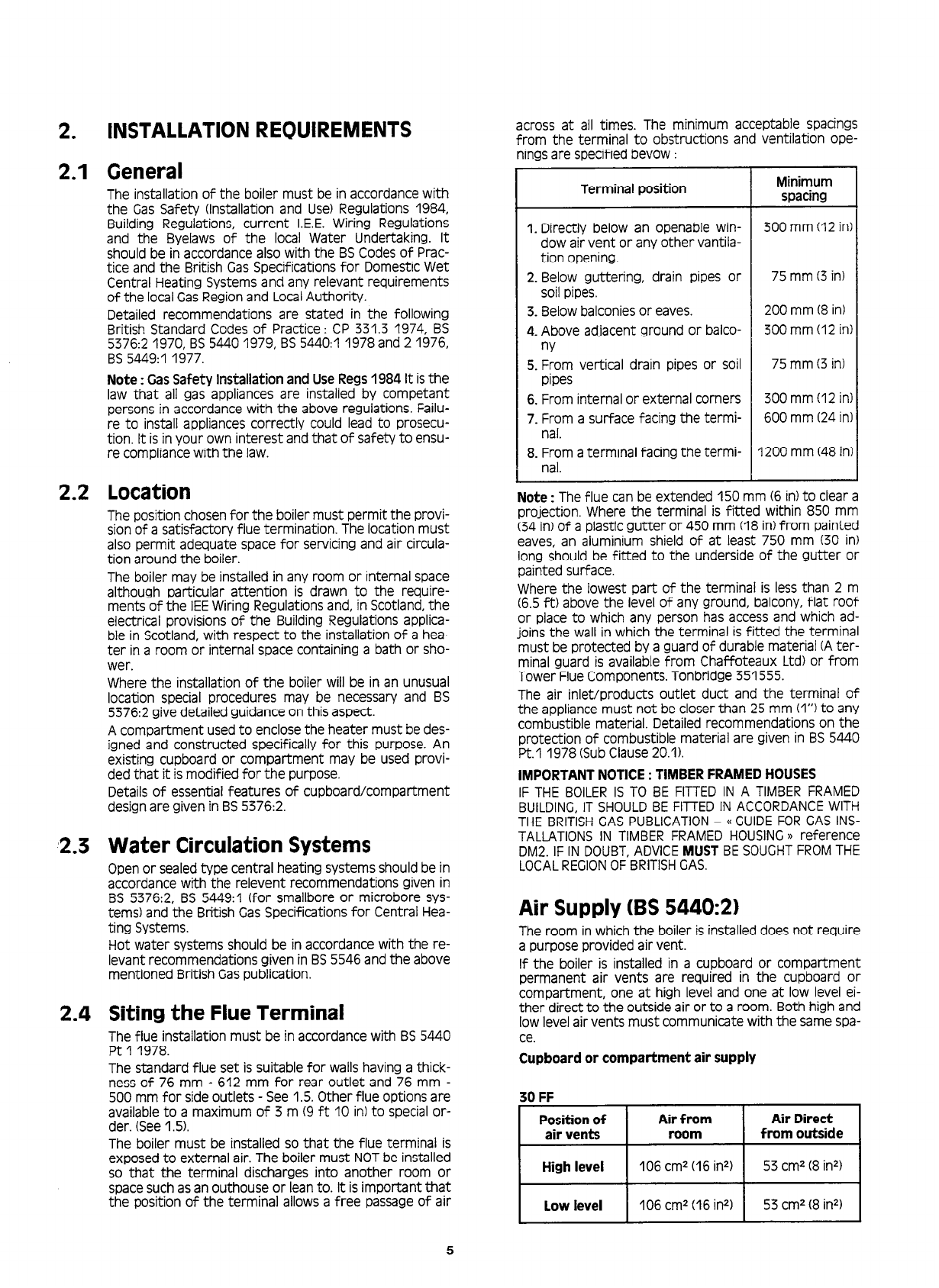
across at all times. The minimum acceptable spacings
from the terminal to obstructions and ventilation ope-
ningsare specified bevow :
Terminal position Minimum
spacing
1. Directly below an openable win- 300 mm (12 in
dow air vent or any other vantila-
tion opening.
2. Below guttering, drain pipes or 75 mm (3in)
soil pipes.
3. Below balconiesor eaves. 200 mm (8 in)
4. Above adjacent ground or balco- 300 mm (12 in
w
5. From vertical drain pipes or soil 75 mm (3 in)
pipes
6. From internal or external corners 300 mm (12 in
7. From a surface facing the termi- 600 mm (24 in
nal.
8. From aterminal facing the termi- 1200 mm (48 in
nal.
Note : The flue can be extended 150 mm (6 in)to clear a
projection. Where the terminal is fitted within 850 mm
(34 in)of a plastic gutter or 450 mm (18 in)from painted
eaves, an aluminium shield of at least 750 mm (30 in)
long should be fitted to the underside of the gutter or
painted surface.
Where the lowest part of the terminal is less than 2 m
(6.5 ft) above the level of any ground, balcony, flat roof
or place to which any person has access and which ad-
joins the wall in which the terminal is fitted the terminal
must be protected by a guard of durable material (Ater-
minal guard is available from Chaffoteaux Ltd) or from
Tower FlueComponents. Tonbridge 351555.
The air inlet/products outlet duct and the terminal of
the appliance must not be closer than 25 mm (I”) to any
combustible material. Detailed recommendations on the
protection of combustible material are given in BS5440
Pt.1 1978 (SubClause20.1).
IMPORTANTNOTICE: TIMBERFRAMEDHOUSES
IF THE BOILERISTO BE FITTEDIN A TIMBERFRAMED
BUILDING,IT SHOULDBE FITrED IN ACCORDANCEWITH
THE BRITISHGASPUBLICATION- ((GUIDEFORGASINS-
TALLATIONSIN TIMBER FRAMEDHOUSING)) reference
DM2. IF IN DOUBT,ADVICEMUST BESOUGHTFROMTHE
LOCALREGIONOFBRITISHGAS.
Air Supply (BS 5440:2)
The room in which the boiler is installed does not require
a purpose provided air vent.
If the boiler is installed in a cupboard or compartment
permanent air vents are required in the cupboard or
compartment, one at high level and one at low level ei-
ther direct to the outside air or to a room. Both high and
low level air vents must communicate with the same spa-
ce.
Cupboard or compartment air supply
30 FF
II
low level 106 cm2(16 in21 53 cm2(8 inn)
5


