3
110503
MAINTENANCE
WARNING:Before doing any maintenance be sure
power is off. At the time you remove a pad frame be sure
to unplug motor and pump. This is for your safety.
SPRING START-UP
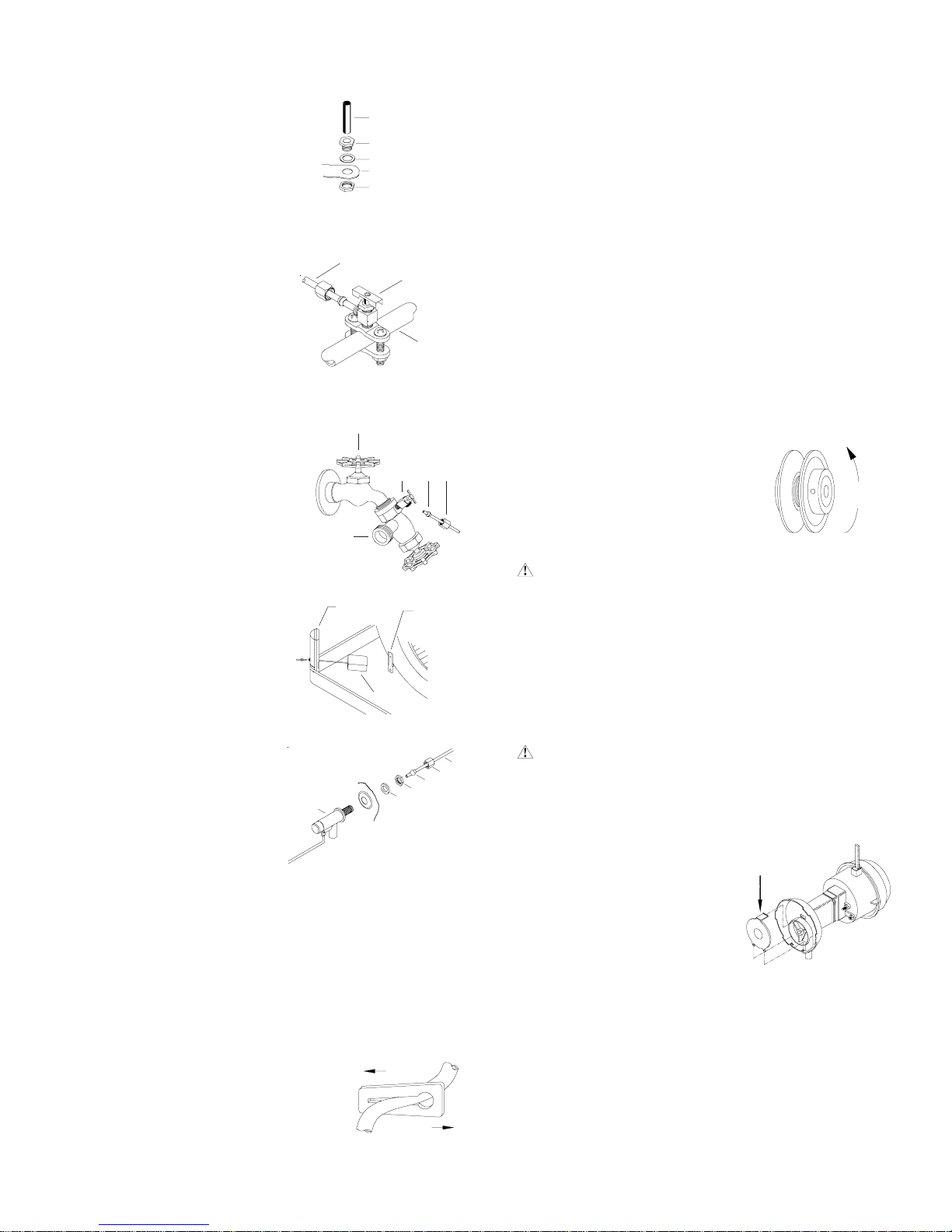
•Clean pump. Cleaning the
pump is necessary once a
year at start-up. For your
safety, turn unit off and unplug
motorandpump. Removethe
pumpfrom the mountslot. Re-
movethe base of the pump as
shown in Fig. 12. Clean the
pump and turn the impeller to
ensure free operation. Re-
move the pump spout and check for any blockage. After
cleaning,reinstallthe base onto the pump. Reattach the pump
to the mount in the cooler using the plastic retainer to ensure
that the pump will not overturn. Do not forget to replace the
spoutand water delivery tube onto the pump outlet. The pump
has an automatic reset thermal protection.
INCREASE
DECREASE
FIG.10
DEPRESSHERE
TO REMOVE
FIG.12
FAUCET
WATER
SUPPLY VALVE
SILLCOCK
FERRULE
NUT
FIG.7
DECREASE
AMPERAGE
FIG.11
FLOAT
CORNER
POST BRACKET
FIG.8
WATER CONNECTION
•Install overflow assembly. Re-
movenutandplace nipple through
the hole in the pan, with the rub-
ber washer between the pan and
the head of the drain nipple (Fig.
5). Screwon nut and draw uptight
againstbottomof pan. Insert over-
flow pipe in nipple to retain water.
Overflow pipe may be removed to
drain pan when necessary. Agar-
denhose may bescrewedon the
drain nipple to drain water away
from your unit.
•Connect water supply line.
Find the closest supply of water.
Use a saddle valve (Fig. 6) to
connect 1/4” tubing to the cold
water supply or use a Sillcock
andwatervalveconnectedto an
outsidefaucet (Fig. 7). Place the
nutandferruleonthetubing and
tighten the nut until water tight.
IMPORTANT: Donotconnectthe
water supply to any soft water
applications. Soft water will
cause corrosion and decrease
the life of the cooler.
•Install float and attach water
line to float. The float may be
installed in either the corner
post or bracket (see Fig. 8).
Refertofigure9for installation
instructions. Insertthefloat (1)
thruthe hole in the corner post
or bracket. Install the washer
(2) and nut (3). Tighten to
keep the float from turning.
Placethe nut (5)andferrule(4)
on the water supply line. Con-
nect to float fitting and tighten
until water tight.
•Fill pan. Allow water to fill to
within 1” of top of pan and ad-
justfloattomaintain this water
level. This can be accom-
plished by bending the float
rod.
•Level water troughs. Operate pump until pads are satu-
rated. Checkeach trough to see if water is evenly dispersed in
the trough. If they are not, loosen adjustment bolts and level
trough. Retighten bolts. Check to see that all pads are satu-
rated with water and that there are no dry spots or openings in
the pads.
•Adjust water amount. Your cooler is equipped with a unique
water metering valve (Fig. 10). The amount of water delivered
to the pads may be decreased by press-
ing the plastic valve as the arrows
indicate. If water is splashing out of wa-
ter troughs, you may need to decrease
the amount of water delivery. Check to
see that all pads are saturated with wa-
ter and that there are no dry spots or
openings in the pads.
AMPERAGE DRAWAND BELT TENSION
This unit is equipped with an adjustable motor drive sheave for
adjustingthe blower wheel speed to the proper loading on differ-
ent duct systems. It is important that the motor drive pulley is
adjusted to correct size to assure maximum air delivery without
damage to the motor. Be sure to follow these instructions care-
fully.
•Adjust drive pulley. After the unit is completely installed, ad-
justthedrive pulley totheleast diameter andadjustbelttension.
See the maintenance section for adjusting belt tension.
•Start cooler. Install all pad frames, start pump, and allow to
operate until pads are wet.
•Check amperage. With pads wet and unit started, check am-
perage draw with an amperage meter.
•Adjust pulley if necessary. If amperage draw is less than
motor rating, turn off electrical power and remove pad frame.
Unplug motor inside cooler, this will protect you from someone
turning on unit while you are working inside. This should be
done for your safety. Adjust pulley to a larger diameter and
readjustbelttension, plug motor in,in-
stall pad frame, and retest amperage
draw. Repeat this process until cor-
rect amperage draw is attained.
Increasing motor pulley diameter in-
creasesamperagedraw. Decreasing
motorpulley diameter decreases am-
perage draw (see Fig. 11).
CAUTION: Do not operate cooler with larger amper-
age draw than specified on motor plate.
NOTE: Noattemptshouldbemadetocompletelyinstallthisunit
without the aid of an electrician or someone familiar with testing
amperage draw. Failure to comply with these instructions may
void your warranty.
COLD
WATER
PIPE
SADDLE
VALVE
1/4” TUBING
FIG. 6
RUBBERWASHER
OVERFLOW PIPE
NIPPLE
BOTTOM PAN
NUT
FIG. 5
FIG.9
123
56
4