9
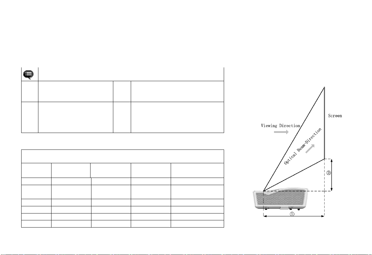
This section takes the installation method of desktop front
projection as an example to explain the picture adjustment for
users' reference.
a. Connect the power supply and start the main unit;
b. According to the picture display, adjust the size and position of
the picture by moving the main unit forward, backward, left
and right or rotating the height adjustment kickstand.
3.2.3 Image Correction
E5F36:
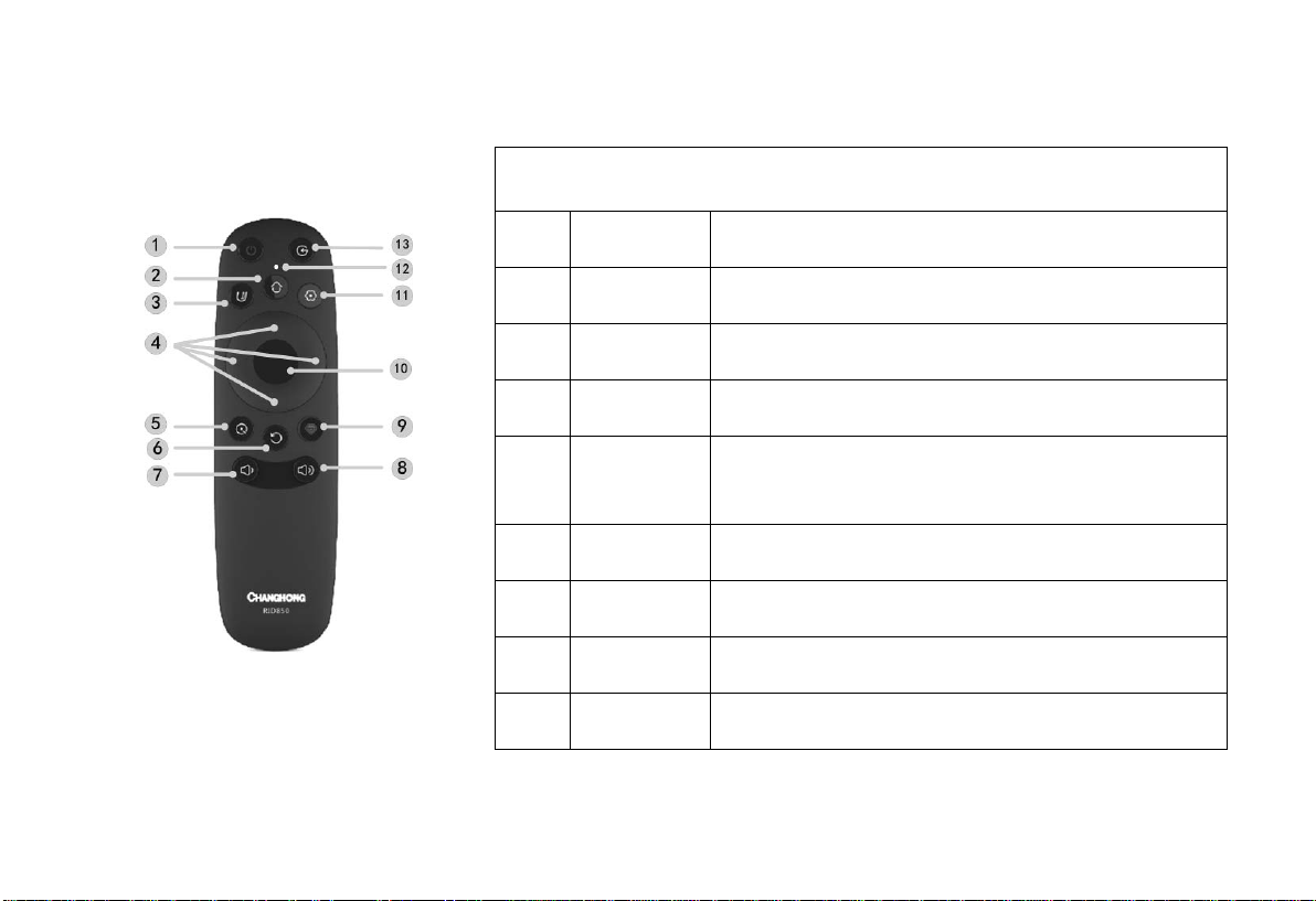
a. Long press the "Menu" key of the remote controller →select
Display Settings →select Image Correction to enter the Image
Correction menu;
b. Select the position to be corrected through the
"Up/Down/Left/Right" key of the remote controller and press
the "OK" key;
c. Adjust vertically through the "Up/Down" key of the remote
controller and horizontally through the "Left/Right" key;
d. After completing the correction of one position, press the
"Return" key, and then repeat the operations of b and c until the
correction of the whole picture is completed.
E5X36 and E5W36
a. Long press the "Menu" key of the remote controller →select
Display Settings →select Image Correction to enter the Image
Correction menu;
b. When the picture is narrow at the top and wide at the bottom,
press the "Left" key to correct, and when the picture is narrow
at the bottom and wide at the top, press the "Right" key to
correct;
c. According to the distortion of the picture, use the "Left/Right"
key to make geometric correction until the picture becomes
square.
3.2.2 Focus Adjustment
a. Call out the electric focusing screen through the user menu: long
press the "Menu" key of the remote controller →select Display
Setting →select the Electric Focusing;
b. Adjust the focal length by pressing the "Left/Right" key of the
remote controller until the picture becomes clear from blur.
3.2 Picture Adjustment
3.2.1 Adjust Image Position