Charles 7305-14 4W-4W User manual
Section 730–514–202
Equipment Issue 2
Second Printing, December 1999Telecommunications Group
1999Charles Industries Ltd.
CLEI is a trademark of Bell Communications Research, Inc.
All rights reserved. Printed in United States of America.
The availability of features and technical specifications herein subject to change without notice. Page 1 of 22
7305–14 4W–4W/2W Prescription Line Amplifier SF to E&M
Module and 7305–19 4W–4W/2W Prescription Line
Amplifier SF to E& M W/Loopback Module
CONTENTS PAGE
Part 1. GENERAL 2. . . . . . . . . . . . . . . . . . . . . . . . . . . . . . . . . . . . . . . . . . . . . . . . . . . . . . . . . . . . . . . . . . . . . . . . . . . . .
Part 2. INSPECTION 3. . . . . . . . . . . . . . . . . . . . . . . . . . . . . . . . . . . . . . . . . . . . . . . . . . . . . . . . . . . . . . . . . . . . . . . . . . .
Part 3. APPLICATION GUIDELINES 3. . . . . . . . . . . . . . . . . . . . . . . . . . . . . . . . . . . . . . . . . . . . . . . . . . . . . . . . . . . . .
Part 4. CIRCUIT DESCRIPTION 3. . . . . . . . . . . . . . . . . . . . . . . . . . . . . . . . . . . . . . . . . . . . . . . . . . . . . . . . . . . . . . . . .
Part 5. MOUNTING 10. . . . . . . . . . . . . . . . . . . . . . . . . . . . . . . . . . . . . . . . . . . . . . . . . . . . . . . . . . . . . . . . . . . . . . . . . . .
Part 6. INSTALLER CONNECTIONS 10. . . . . . . . . . . . . . . . . . . . . . . . . . . . . . . . . . . . . . . . . . . . . . . . . . . . . . . . . . . .
Part 7. OPTIONS 11. . . . . . . . . . . . . . . . . . . . . . . . . . . . . . . . . . . . . . . . . . . . . . . . . . . . . . . . . . . . . . . . . . . . . . . . . . . . .
Part 8. ALIGNMENT 15. . . . . . . . . . . . . . . . . . . . . . . . . . . . . . . . . . . . . . . . . . . . . . . . . . . . . . . . . . . . . . . . . . . . . . . . . .
Part 9. TESTING 17. . . . . . . . . . . . . . . . . . . . . . . . . . . . . . . . . . . . . . . . . . . . . . . . . . . . . . . . . . . . . . . . . . . . . . . . . . . . .
Part 10. TECHNICAL ASSISTANCE 18. . . . . . . . . . . . . . . . . . . . . . . . . . . . . . . . . . . . . . . . . . . . . . . . . . . . . . . . . . . . .
Part 11. WARRANTY & CUSTOMER SERVICE 18. . . . . . . . . . . . . . . . . . . . . . . . . . . . . . . . . . . . . . . . . . . . . . . . . . .
Part 12. SPECIFICATIONS 20. . . . . . . . . . . . . . . . . . . . . . . . . . . . . . . . . . . . . . . . . . . . . . . . . . . . . . . . . . . . . . . . . . . . .
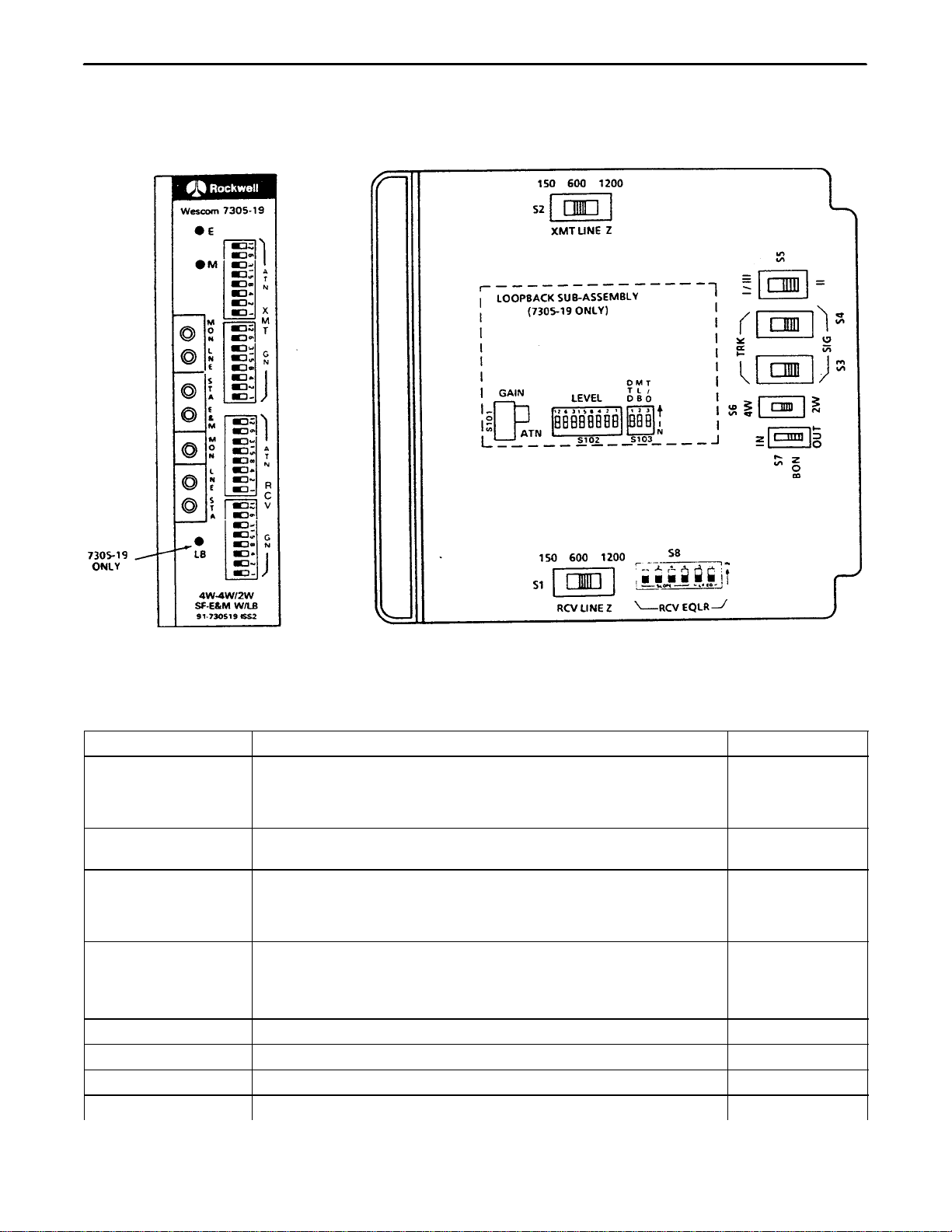
Figure 1. 7305–19 4W–4W/2W SF To E&M W/LBK Module

Section 730–514–202
2
1. GENERAL
1.1 Document Purpose
This document provides general, installation, alignment and testing information for the 7305–14 and 7305–19
4W–4W/2W Prescription Line Amplifier SF to E&M modules.
1.2 Document Status
This document is reprinted to provide a general editorial update.
1.3 Equipment Function
The 7305–14 and 7305–19 4W–4W/2W Prescription Line Amplifier SF to E&M are 400-type plug-in combined
function modules (CFMs). Each combines the features and circuit of a 4-wire to 4-wire or 2-wire repeater and an
SF to E&M signaling unit. The CFMs differ only in that the 7305–19 contains the loopback function. The 7305–19
module is shown in Figure 1.
1.4 Equipment Location/Mounting
The units mount in TL40XX mounting assemblies or unwired 400-type mounting assemblies.
1.5 Equipment Features
The CFMs provide the following features:
1.5.1. Transmission
Switch-selectable 4W to 4W, or 4W to 2W operation
Switch-selectable line side terminating impedance of 150, 600 or 1200 ohms
4W station side terminating impedance of 600 ohms
2W station side terminating impedance of 600 ohms in series with 2.15 uF
Transformer coupled line and station Interface
Line side surge protection
Receive and transmit prescription gain or attenuation of 24dB in 0.1dB steps
Receive prescription (post) equalization for H88 loaded or nonloaded cable
2W port Build-Out-Network (BON)
Seven front-panel-mounted bantam test jacks; receive line and monitor; transmit line and monitor;
receive station out; transmit station in; and E&M drop (E-tip, M-ring) jack
Integral 2600Hz transmit oscillator
1.5.2. Signaling
Switch-selectable E&M interface: signaling mode (M-send, E-receive) or trunk mode (E-send,
M-receive)
Switch-selectable TYPE I, TYPE II or TYPE III signaling interface
Transmit and receive pulse correction
M-lead current limiting
Front-panel-mounted LEDs that indicate the status of the E&M leads

Section 730-514-202
3
1.5.3. Loopback (7305–19 Only)
2713Hz tone-activated loopback
Equal level loopback with gain of 0 to +/–24dB in 0.1dB steps
Loops back SF signaling and busies the E&M leads
Manual Loopback (MLB) switch
Tone Loopback Disable (DTD) switch
Front-panel-mounted LB LED that indicates loopback status
4/20 minute loopback time–out switch
Full 5-year warranty
2. INSPECTION
2.1 Inspect for Damages
Inspect the equipment thoroughly upon delivery. If the equipment has been damaged in transit, immediately re-
port the extent of damage to the transportation company.
2.2 Equipment Identification
Charles Industries’ equipment is identified by a model and issue number imprinted on the front panel or located
elsewhere on the equipment. Each time a major engineering design change is made on the equipment, the issue
number is advanced by 1 and imprinted on subsequent units manufactured. Therefore, be sure to include both
the model number and its issue number when making inquiries about the equipment.
3. APPLICATION GUIDELINES
The CFMs can be applied as Network Channel Terminating Equipment (NCTE) on special service circuits de-
scribed by any one of the following FCC Facility Interface Codes: (4W–4W) TL31M, TL31E, TC31M, TC31E,
TL32M, TL32E, TC32M, TC32E; and (4W–2W) TL11M, TL11E, TL12M and TL12E. The CFMs can be used in
central office or station applications and provides all necessary circuit functions to interface a 4-wire SF facility to
a PBX trunk circuit. See Figure 2, Figure 3 and Figure 4.
Figure 5 and Figure 6 illustrate typical 7305–14 and 7305–19 station and central office applications.
4. CIRCUIT DESCRIPTION
The CFMs provide signaling and transmission Interface between a 4-wire facility and a 2-wire or 4-wire circuit.
They also provide level control in both the transmit and receive paths. Refer to Figure 7 and Figure 8, the
7305–14 (Issue 2) and 7305–19 (Issue 2) block diagrams, while reading the following circuit description.
4.1 Transmit Voice Path
The transmit voice path of the CFMs is connected to the 4W/2W XMT STA at a fixed impedance of 600 ohms
(600 ohms in series with 2.15uF for 2W). The transmit voice path contains an attenuator stage (XMT ATN) pro-
viding up to 24dB of attenuation in 0.1dB steps. The XMT ATN stage is used to set the internal –16TLP (trans-
mission level point) from the 4W/2W XMT STA level.
The –16TLP output of the XMT ATN stage is routed through the XMT FET SWITCH to the XMT GN (transmit
gain) stage. The XMT GN stage provides up to 24dB of gain in 0.1dB steps. This allows the transmit line level to
be set from the internal –16TLP. The output of the XMT GN stage is transformer coupled to the XMT LINE and
provides 150, 600 or 1200 ohm impedance matching toward the cable facility. The net result of the XMT ATN and
XMT GN stages is to allow the CFMs to accommodate both line and station equipment levels between + 7 and
–16dBm.

Section 730–514–202
4
4.2 Receive Voice Path
The receive voice path of the CFMs is transformer coupled to the RCV LINE and provides a 150, 600 or 1200
ohm terminating impedance toward the facility. The receive voice path contains a gain stage (RCV GN) providing
up to 24dB of gain in 0.1dB steps. The RCV GN compensates for cable loss and is used to set the internal +
7TLP for the SF RECEIVER.
Figure 2. 7305–14/19 SIG/TRK Connecting Circuits With Type I E&M Signaling
Figure 3. 7305–14/19 SlG/TRK Connecting Circuits With Type II E&M Signaling
Figure 4. 7305–14/19 SlG/TRK Connecting Circuits With Type III E&M Signaling
Section 730-514-202
5
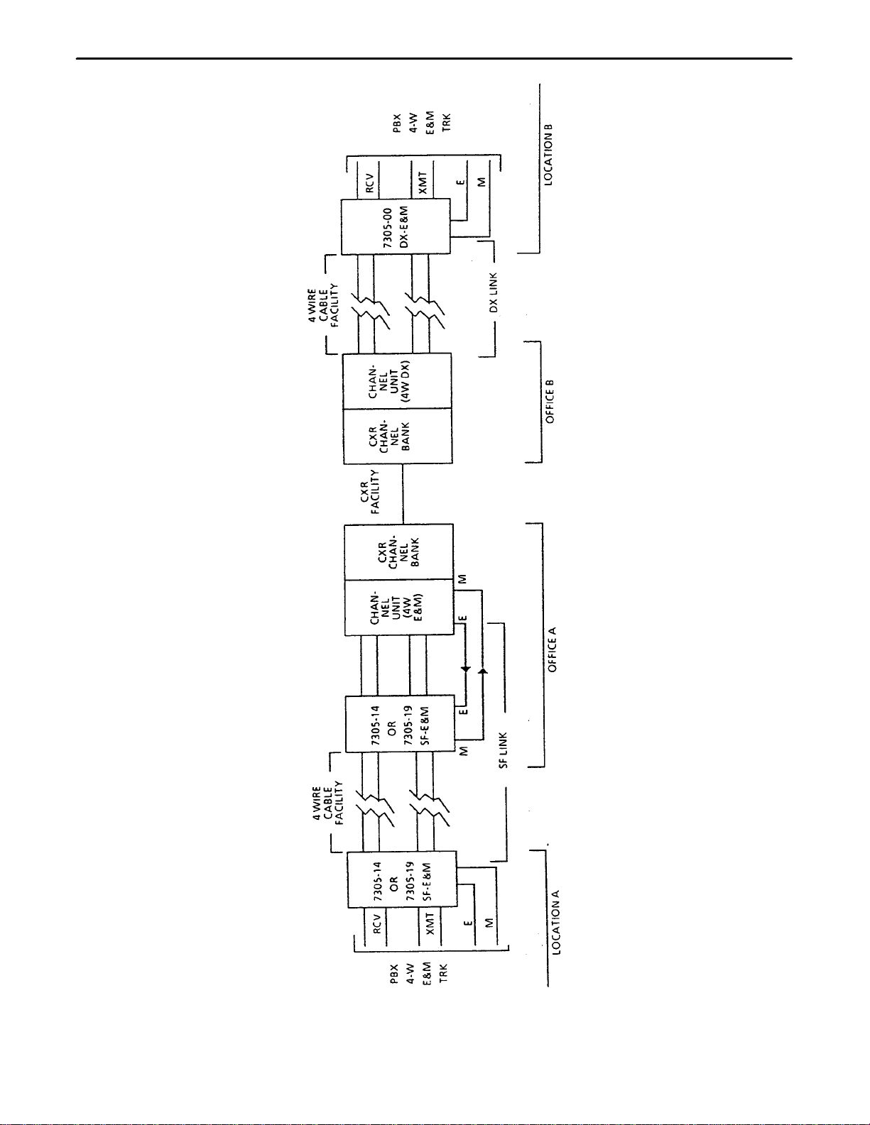
Figure 5. Typical 4W–4W Application For 7305–14/19
Section 730–514–202
6
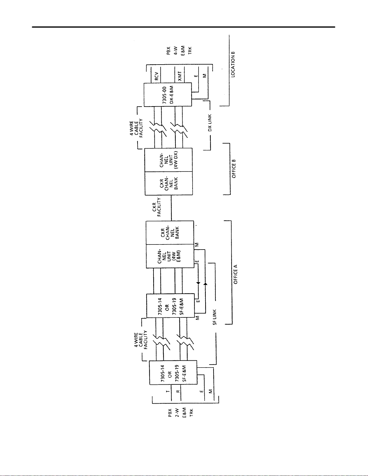
Figure 6. Typical 2W–4W Application For 7305–14/19
Section 730-514-202
7
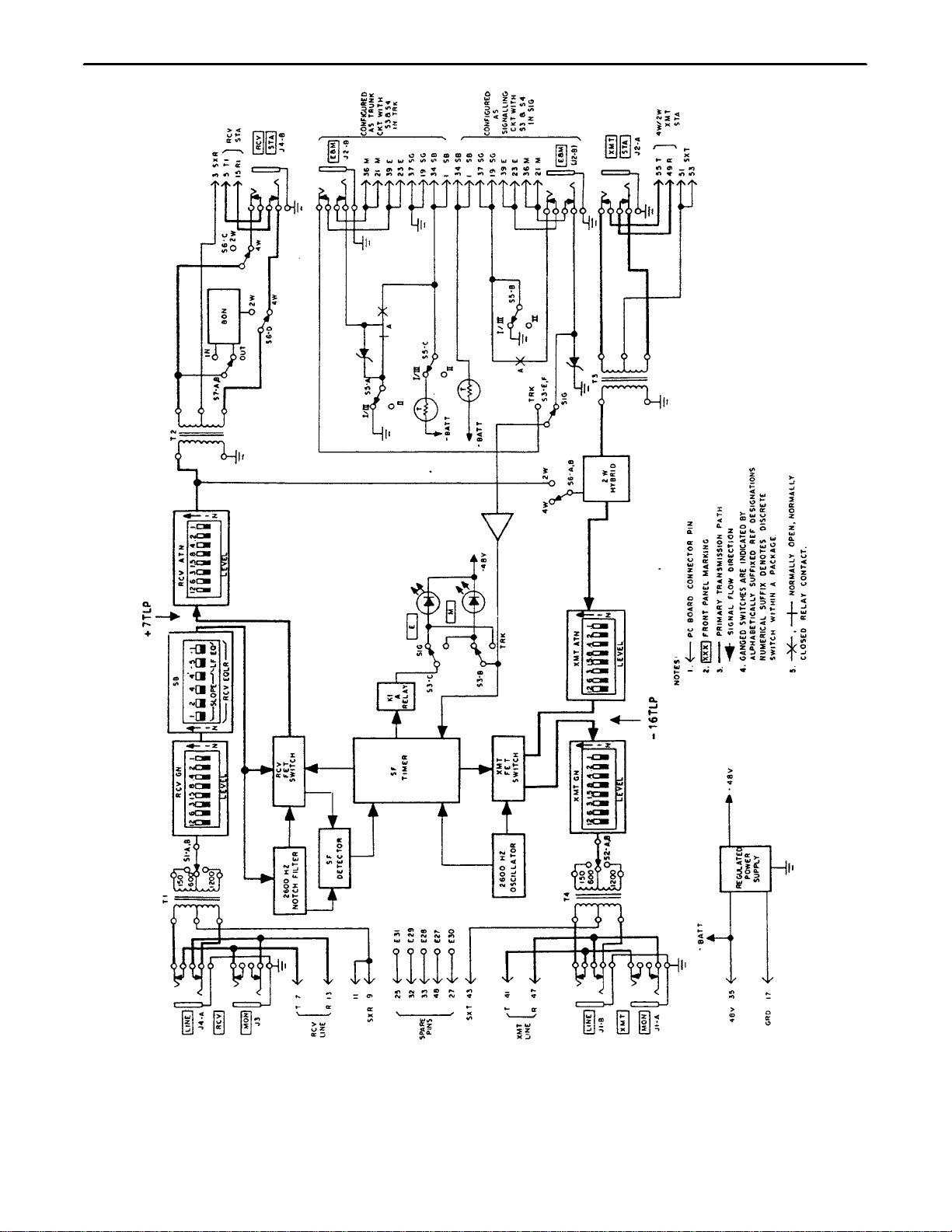
Figure 7. 7305–14 4W–4W/2W SF To E&M (Issue 2) Block Diagram

Section 730–514–202
8
Figure 8. 7305–19 4W–4W/2W SF To E&M W/LBK (Issue 2) Block Diagram

Section 730-514-202
9
The + 7TLP output of the RCV GN is routed to the RCV EQLR (receive equalizer) which provides amplitude
equalization for loaded and nonloaded cable facilities. The output of the RCV EQLR is applied to the SF RECEIV-
ER and the RCV ATN (receiver attenuator) thru the RCV FET switch. The RCV ATN provides up to 24dB of at-
tenuation in 0.1dB steps for setting the receive station equipment level. For 4W operation the output of the RCV
ATN is applied the 4W RCV STA. For 2W operation the output of the RCV ATN is applied to the 2W HYBRID and
then to the 4W/2W XMT STA. The net result of the RCV GN and RCV ATN stages is to allow the CFMs to ac-
commodate both line and station equipment levels between + 7 and –16dBm.
4.3 Signaling Interface
The CFMs provide E&M leads to the station equipment. The E&M leads can be conditioned to appear as a trunk
or signaling circuit. They can also be optioned for Type I, II or III E&M lead signaling modes. See Figure 2,
Figure 3 and Figure 4.
4.4 SF Receiver Circuitry
The SF receiver consists of the 2600Hz NOTCH FILTER, SF DETECTOR, SF TIMER, and the RCV FET
SWITCH. The input to the SF receiver comes from the output of the RCV EQLR. This insures that the receiver
input is at a + 7TLP. The idle SF tone is –20dBm0, which means that the low level or idle SF tone level is
–13dBm, while high level SF tone is –1dBm (–8dBm0). High level tone is received during dial pulsing and for 400
milliseconds following off-hook to on-hook transition. The output of the SF receiver is connected to the SF TIM-
ER.
The SF TIMER with the RCV FET SWITCH controls the insertion and removal of the 2600Hz NOTCH FILTER in
the receive voice path. The 2600Hz NOTCH FILTER is inserted in the voice path within 13 milliseconds of the SF
receiver detecting 2600Hz tone to prevent this signaling tone from reaching the 4W RCV STA. The 2600Hz
NOTCH FILTER is removed 50 milliseconds (nominally) after the SF receiver signals the loss of the SF tone, but
remains inserted for 225 milliseconds if SF tone was not present for 175 milliseconds.
The SF TIMER with the RCV FET SWITCH also controls the guard circuit of the SF DETECTOR. The guard cir-
cuit is disabled when SF tone has been received for 225 milliseconds or more. This places the SF receiver in the
broadband detection mode, allowing noise and frequencies other than 2600Hz to aid in maintaining the idle condi-
tion. The guard circuit is enabled 50 milliseconds (nominally) after the loss of SF tone, which places the SF re-
ceiver in the narrow band condition. With the SF receiver in the narrow band condition, SF signaling tone must be
10dB greater than the broadband energy for the SF receiver to recognize it as valid signals. This reduces talk-off,
while dial pulses and winks are easily passed because they are high level 2600Hz tone.
The SF TIMER contains a receive pulse corrector and an A relay driver circuit which corrects input pulsing. When
receiving a tone-on indication the A relay driver holds the A RELAY released. The absence of SF tone causes the
receive pulse corrector to turn on the A relay driver which operates the A RELAY. For receive pulse corrector re-
sponse to pulsed SF tone, see RECEIVE PULSE CORRECTION in Part 11.
4.5 SF Transmitter Circuitry
The SF transmitter consists of the 2600Hz OSCILLATOR; the XMT FET SWITCH; and the XMT tone on/off, XMT
level and XMT cut controls which are part of the SF TIMER.
The XMT cut control timing, controls the XMT FET SWITCH causing the transmit path to be cut and uncut in the
following manner: When the SF receiver is receiving continuous SF tone and the transmit signaling interface input
is at idle, the transmit voice path is cut continuously. If the receive SF tone is removed and the transmit signaling
interface input remains idle, the XMT cut is affected for approximately 550 milliseconds. If the receive SF tone is
on continuously and the transmit signaling interface input goes busy, the transmit voice path is cut for approxi-
mately 125 milliseconds. The transmit voice path is cut within 10 milliseconds of the transmit signaling interface
change of state from busy to idle.
The XMT tone on/off control places or removes SF tone from the transmit voice path toward the line. SF tone en-
ters the transmit voice path at a –16dB TLP; the SF tone is at –20dBm0. Therefore, low level SF tone is –36dBm
and high level SF tone is –24dBm.
The XMT level control operates the tone level control FET which is part of the XMT FET SWITCH. The XMT level
control closes the tone level control FET in a few milliseconds allowing high level SF tone from the 2600Hz OS-
CILLATOR to pass. The XMT level control opens the tone level control FET approximately 400 milliseconds after
the transmit signaling interface goes idle. This action allows dialing information to be transmitted as high level SF
tone.

Section 730–514–202
10
4.6 Power Supply
The on-board REGULATED POWER SUPPLY derives the necessary voltages to operate the CFMs from a
–48VDC (nominal) source and power return ground applied at pins 35 and 17 respectively.
4.7 2713Hz Tone Activated Loopback (7305–19 Only)
The 7305–19 provides tone-operated loopback toward the 4W facility. A continuous 2713Hz loopback control sig-
nal applied to the RCV LINE for a minimum of 2 seconds satisfies the first condition for loopback operation. Upon
removal of the 2713Hz tone, the final condition is satisfied, operating and latching the LB RELAY and illuminating
the LB LED. The LB RELAY performs the following functions while operated:
Loops all voice-band signals from the RCV STA to the XMT STA at equal loopback levels. Up to
+/–24dB gain (switches S101 and S102) is provided to accommodate a full range of TLPS.
Opens the RCV STA and XMT STA paths to the equipment, preventing transmission.
Internally conditions the E&M leads to loopback the signaling circuit.
Busies the E or M lead to the station equipment.
Loopback release is accomplished by the reapplication of 2713Hz tone to the 7305–19. After the 2713Hz tone is
received for approximately 0.9 seconds, the LB RELAY releases and the LB LED extinguishes, ending the loop-
back condition.
The LOOPBACK LEVEL AND CONTROL is conditioned by DIP switch S103. The tone detector can be disabled
by placing the DTD switch of S103 to the IN position. Manual loopback can be enabled by placing the MLB switch
of S103 to the IN position. The LOOPBACK LEVEL AND CONTROL also contains a four minute time-out function
that, when enabled, will automatically reset the loopback to its normal condition four minutes after the tone acti-
vated loopback is started. This function is enabled by placing switch T/O of S103 to the OUT position. Time-out is
20 minutes with T/O of S103 in the IN position.
5. MOUNTING
The 7305–14 and 7305–19 are 400-type plug-in combined function modules (CFMs) designed to mount in
TL40XX Mounting Assemblies. They can also be mounted in one position of unwired 400-type mounting assem-
blies or in the transmission position of 72 Family Mounting Assemblies.
Installation and removal of modules should be done with care. Do not force a module into place. If
excessive resistance is encountered while installing a module, remove the module and check the card
guides and connector to verify proper alignment and the absence of foreign material.
CAUTION
6. INSTALLER CONNECTIONS
When the 7305–14/19 is installed in a 400-type mounting assembly, it makes electrical connections to associated
equipment through a 56-pin, wire-wrap, card-edge connector, provided as part of the mounting assembly. Make
all installer connections to this connector in accordance with Table 1.
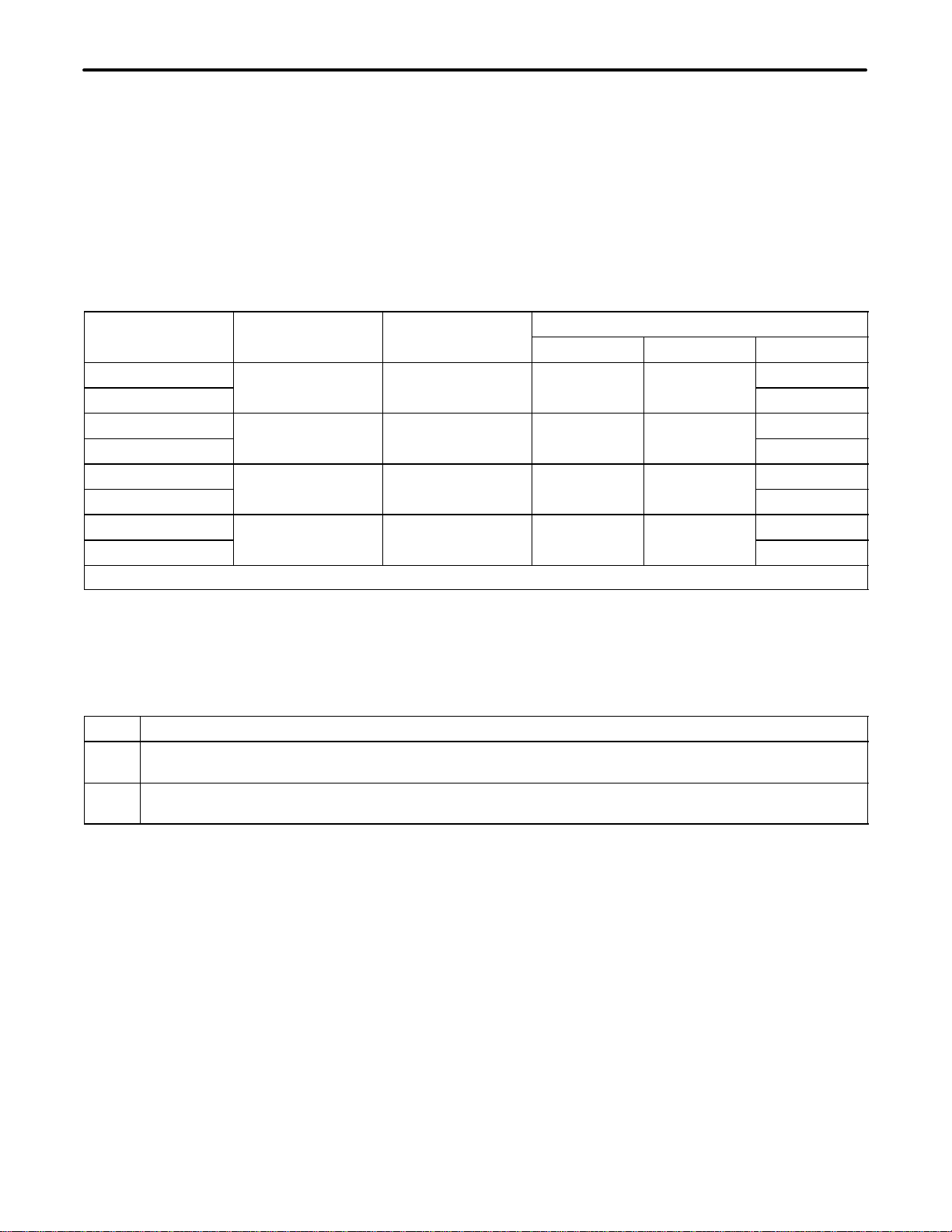
Table 1. 6305–14/19 Installer Connections
Lead Designation Pin
4W RCV STA T1
R1 5
15
2W/4W XMT STA T
R55
49
2W/4W XMT STA SX
4W RCV STA SX SXT
SXR 51, 53
3

Section 730-514-202
11
Lead Designation Pin
RCV LINE T
R7
13
XMT LINE T1
R1 41
47
XMT LINE SX
RCV LINE SX SXT
SXR 43
9, 11
E & M SIGNALING LEADS E
SG
M
SB
39, 23
37, 19
36, 21
34, 1
7305–19 ONLY MLB 18
–48 V
GRD 35
17
SPARE PINS E27
E28
E29
E30
E31
48
33
32
27
25
7. OPTIONS
The CFMs are equipped with DIP switches, slide switches and a screw option that are used to condition the mod-
ules for proper application and operation. Refer to Figure 9 for the locations of these options while reading the
following optioning instructions.
7.1 Switches S1 And S2 (RCV Z And XMT Z)
The RCV Z (S1) and XMT Z (S2) switches are used to select 150, 600 or 1200 ohms for line-side impedance
matching. Option per Table 2.
Table 2. 4W Line Impedance Selection
4W Cable Impedance Selection (Ohms, S1 & S2 position)
Nonloaded 150,600
H88 Loaded 1200
Mix loaded and non-
loaded
1 50/600 if distance between the 7305–14/19 and the first load coil is greater than 9 kft.
loaded 1200 if distance between the 7305–14/19 and the first load coil is less than 9 kft.
7.2 Switches S3 And S4 (SIG/TRK) Switch S5 (TYPE I/III Or TYPE II)
Condition the 7305–14/19 for signaling/trunk and Type I/Type III or Type II operation according to Table 3. The
7305–14/19 E&M leads appear as signaling E&M leads when S3 and S4 are in the SIG position. The E&M leads
appear as trunk E&M leads when S3 and S4 are in the TRK position. S5 is placed in the TYPE I/III position for
conventional (nonlooped) E&M operation or in the TYPE II position for (looped) E&M operation.
7.3 Switch S6 (2W/4W Station Interface)
Place S6 in the 2W or 4W position. Refer to Table 3.
Section 730–514–202
12
7.4 Front Panel RCV and XMT GN/ATN Switches(Transmission Level Adjustment)
The RCV GN, ATN DIP switches and the XMT GN, ATN DIP switches are used to provide up to 24dB of prescrip-
tion gain or attenuation in 0.1dB increments. See Part 8 for alignment of the receive and transmit voice paths.
7.5 Switch S7 [BON (Build-Out-Network)]
Switch S7 is used to balance out the DC resistance and capacitance of a 2W cable. If the 2W cable is 100 to 250
feet of 26 AWG wire, place S7 in the IN position. If the 2W cable is less than 100 feet of 26 AWG, place S7 in the
OUT position.
Table 3. SIG/TRK, Type I/Type II/Type III, And 2W/4W Station Interface Conditioning With FCC Facility
Code Cross References*
FCC Code Signaling Inter-
face
E&M Interface Switch Positions
face S3 and S4 S5 S6
TL31M or TC31M Type I (non-looped) Signaling SIG Type I/III 4W
TL11M 2W
TL31E or TC31E Type I (non-looped) Trunk TRK Type I/III 4W
TL11E 2W
TL32M or TC32M Type II (looped) Signaling SIG Type II 4W
TL12M 2W
TL32E or TC32E Type II (looped) Trunk TRK Type II 4W
TL12E 2W
*For type III operation, place switch S5 in the TYPE I/III position.
7.6 Switches On S8 [Receive Equalization Adjustment (RCV EQLR)]
The RCV EQLR switches on S8 are used to provide up to 11dB of prescription equalization (1000 to 2800Hz) in 1
dB increments and up to –1.5dB of low frequency equalization (1000 to 400Hz) in –0.5dB increments. The equal-
izer pivots around 1000Hz so no RCV LEVEL readjustment is required. Condition the receive equalizer according
to Table 6 and the following:
Step Action
1. Determine the 2800Hz and 400Hz losses of the cable with respect to the 1000Hz loss (loss should be
expressed as a positive number, gain as a negative number).
2. Find a line from Table 6 that best matches the facility response and set the switches on S8 as required
by that line. (See EXAMPLE below.)
Note: Choose a response from the table such that the 2800Hz level is less than or equal to the 1000Hz level.
EXAMPLE (For Cable Equalization)
1. 2800Hz cable loss equals 13.1dB.
2. 1000Hz cable loss equals 5.7dB.
3. 400Hz cable loss equals 1.7dB.
4. 2800Hz loss with respect to 1000Hz equals ( + 13.1dB) –( + 5.7dB) = + 7.4dB.
5. 400Hz loss with respect to 1000Hz equals (+ 1.7dB) –( + 5.7dB) = –4.0dB.
6. Choose the line: 2800Hz = + 7.2dB, 400Hz = –4.1dB.
Section 730-514-202
13
7. Set switches on S8 as follows: 1, 2, 4 and –1 to IN; and 4’ and –.5 to OUT.
Note: When no equalization is required or a flat frequency response of the receive amplifier is desired, place
all switches on S8 to OUT.
Figure 9. 7305-14 And 7305-19 Option Locations
Table 4. 7305-14 And 7305-19 Option Description
Switch Designation Switch Function Switch Position
S1, S2 150 Ohm line impedance
600 Ohm line impedance
1200 Ohm line impedance
150
600
1200
S3, S4, S5, and S6 E & N trunk/signaling, type I/III E & M non-looped, type II E&M
looped, and 2W/4W station See Table 3
S7 2W port build-out-network (BON):
To balance 100 to 250 feet of 26 gauge cable
To balance less than 100 feet of cable IN
OUT
S8 Cable equalization, loaded and/or nonloaded. Provides up to 11 dB
of receive equalization (1000 to 2800 Hz) in 1dB steps using
switches 1, 2, 4, and 4’ and up to –1.5 dB of receive equalization
(1000 to 400 Hz) in –0.5 dB steps using switches –.5 and –1
See Table 5
Front Panel RCV GN RCV path gain adjustment of up to +24 dB in 0.1 dB steps See Table 4
Front Panel XMT GN XMT path gain adjustment of up to +24 dB in 0.1 dB steps See Table 4
Front Panel RCV ATN RCV path attenuation adjustment of up to +24 dB in 0.1 dB steps See Table 4
Front Panel XMT ATN XMT path attenuation adjustment of up to +24 dB in 0.1 dB steps See Table 4

Section 730–514–202
14
Switch Designation Switch PositionSwitch Function
7305–19 only
S101 GAIN/ATN and
S102 level S101 provides loopback gain or attenuation: S102 provides up to
24 dB, in 0.1 dB steps, for loopback level adjustment. See Table 4
S103 loopback control Disable tone detector (DTD)
Manual loopback (MLB)
4-minute time–out (T/O)
Note: 20 minute time-out with S103-3 IN.
S103–1 IN
S103–2 IN
S103–3 OUT
Table 5. Transmit Or Receive Adjustment (Front Panel DIPs)
XMT or RCV Level XMT or RCV Gain
Switch On GN ATN
12
6
3
1.5
.8
.4
.2
.1
+12
+6
+3
+1.5
+0.8
+0.4
+0.2
+0.1
–12
–6
–3
–1.5
–0.8
–0.4
–0.2
–0.1
7.7 Switches S101 And S102 (Equal Level Loopback) 7305–19 Only
The loopback circuit contains a prescription gain or attenuation circuit for the purpose of obtaining equal level
transmission loopback. Condition the loopback level (S101 and S102) according to Table 5 and the following:
Step Action
1. Determine the required gain or attenuation by subtracting the RCV STA TLP from the 4W/2W XMT STA
TLP.
2. Program the required level by setting the switches on S102 equal to the gain calculated in Step (a)
+/–0.05dB. Place switch S101 in the GAIN position if the result is positive; place switch S101 to the
ATN (attenuation) position if the result is negative.
7.8 Switch S103 ( Loopback Control) 7305–19 Only
Switches 103–1, –2, and –3 control the Disable Tone Detector (DTD), the Manual Loopback (MLB), and Loop-
back time–out T/O respectively.
Step Action
1. To disable the tone-activated loopback, place switch S103–1 (DTD) to the IN position.
2. To manually loopback the module, place switch S103–2 to the IN position. The module will remain
looped back regardless of the position of S103–1 (DTD) or S103–3(T/O).
Note: The module can also be manually looped back by connecting ground to pin 18 of the wire
wrap cardedge connector.
3. To activate a four minute time–out of the tone-activated loopback, place switch S103–3 (T/O) to the
OUT position. With S103–3 in the OUT position, the tone-activated loopback condition will be deacti-
vated upon application of 2713Hz tone or will time–out after four minutes.
Note: Time-out is 20 minutes with S103-3 in the IN position.

Section 730-514-202
15
Table 6. Loaded/Nonloaded Cable Equalization
S8 Switches ’IN” (X) Equalizer Gain
dB* S8 Switches ’IN’ (X) Equalizer Gain
dB*
Slope LF EQ 2800
Hz
400 Hz Slope LF EQ 2800
Hz
400 Hz
1 2 4 4’ –.5 –1 Hz 1 2 4 4’ –.5 –1 Hz
0.0 –0.4 X X +6.0 –2.5
X +0.2 –0.9 X X X +6.1 –3.0
X +0.2 –1.4 X X X +6.2 –3.6
X X +0.3 –2.2 X X X X +6.3 –4.4
X +1.0 –0.9 X X X +7.0 –3.1
X X +1.1 –1.4 X X X X +7.1 –3.6
X X +1.2 –1.9 X X X X +7.2 –4.1
X X X +1.3 –2.3 X X X X X +7.3 –4.9
X +2.0 –1.1 X X +8.0 –4.3
X X +2.1 –1.6 X X X +8.1 –4.8
X X +2.2 –2.1 X X X +8.2 –5.2
X X X +2.3 –2.9 X X X X +8.3 –5.8
X X +3.0 –1.7 X X X +9.0 –4.8
X X X +3.1 –2.1 X X X X +9.1 –5.3
X X X +3.2 –2.7 X X X X +9.2 –5.9
X X X X +3.3 –3.5 X X X X X +9.3 –6.6
X +4.0 –1.9 X X X +10.0 –5.0
X X +4.1 –2.3 X X X X +10.1 –5.5
X X +4.2 –2.9 X X X X +10.2 –6.0
X X X +4.3 –3.6 X X X X X +10.3 –6.8
X X +5.0 –2.4 X X X X +11.0 –5.6
X X X +5.1 –2.9 X X X X X +11.1 –6.0
X X X +5.2 –3.4 X X X X X +11.2 –6.6
X X X X +5.3 –4.2 X X X X X X +11.3 –7.3
*Referenced to 1000 Hz level. (1000 Hz gain is 0dB for all equalization settings.)
Note: When no equalization is required, or flat frequency response of the receive amplifier is desired, place all
switches on S8 to OUT.
8. ALIGNMENT
The CFMs contain gain controls which must be adjusted to set the transmit line and receive station TLPs (trans-
mission level points). They also contain controls for receive amplitude equalization. Use the following procedures
to align the receive voice path and the transmit voice path. Be certain that all options have been properly condi-
tioned for the application in accordance with Part 7 before beginning the alignment procedure.
The following test equipment is required to properly align the CFMS.
Transmission Measuring Set (TMS): WECO 23A, Hewlett-Packard 3550, or equivalent with self-con-
tained Variable Frequency Oscillator (VFO)

Section 730–514–202
16
Three-conductor test cords having one end terminated in bantam plugs and the other end suitable for
connecting to the TMS and VFO.
Note: If TMS or VFOconnecting cords are terminated in Type 310 plugs, they can be adapted for connecting
into bantam jacks by attaching a Charles Type 310 to Bantam Jack Adapter (14 inch) (p.n. 003-210367).
One open bantam plug.
8.1 RCV Alignment Procedure
Use the following steps to perform the receive alignment procedure.
Step Action
1. RCV Facility Verification
Arrange the TMS for terminated measurement at the impedance specified on the CLR. Connect the
TMS to the RCV MON jack on the front panel of the CFM. Insert and open bantam plug into the RCV
LINE jack on the CFM to disconnect the CFM from the RCV LINE.
2. Request the distant terminal to send a 1000Hz test tone at the required level and impedance specified
on the CLR.
3. Record the level measured on the TMS. If the recorded level is not at the level specified on the CLR,
locate and correct the facility fault before proceeding.
4. If equalization is required, request the distant terminal to send a 2800 Hz test tone and the a 400 Hz
test tone at the required level and impedance specified on the CLR. Record the levels measured on the
TMS.
5. RCV Gain Adjustment
Calculate the required RCV GN setting by subtracting the 1000 Hz level recorded in Step 3, from +7
dB, SF receiver TLP. Set the RCV ATN switches to off (located on the front panel).
6. Program the required RCV gain by setting the RCV GN switches (located on the front panel) equal to
the gain calculated in Step 5 +/–0.05 dB. See Table 4.
7. If no equalization is required, ensure that all switches on S8 are out (off). Proceed to step 10.
8. Cable Equalization
Calculate the required equalization by subtracting the 2800 Hz level recorded in Step 4 from the 1000
Hz level recorded in Step 3. Also subtract the 400 Hz level recorded in Step 4 from the 1000 Hz level
recorded in Step 3.
9. Using the 2800 Hz and 400 Hz loss figures calculated in Step 8 and Table 5, locate the row that most
accurately matches the required equalization. Program S8 RCV EQLR by setting the indicated (X)
equalizer switches IN (ON).
10. RCV Attenuator Adjustment
Calculate the required RCV ATN setting by subtracting the receive station equipment level, specified on
the CLR from +7TLP.
11. Program the required RCV attenuation by setting the RCV ATN switches (located on the front panel)
equal to the attenuation calculated in Step 10, +/–0.05 dB. See Table 4.
12. Remove all test cords.
13. Receive Station Equipment Verification
Arrange the TMS for 600 ohm terminated measurement. Connect the TMS to the RCV STA jack on the
front panel of the CFM.
14. Request the distant terminal to send a 1000 Hz, a 2800 Hz, and then a 400 Hz test tone at the required
level and impedance specified on the CLR.
15. Verify that the levels measured on the TMS are those specified on the CLR.
16. Remove all test cords and perform the transmit alignment procedure.

Section 730-514-202
17
8.2 Transmit Alignment Procedure
Use the following steps to perform the transmit alignment procedure.
Step Action
1. Condition the local VFO to apply a 1000 Hz test tone at the required level and impedance specified on
the CLR. Connect the VFO to the XMT STA jack on the front panel of the CFM.
2. Arrange the TMS for terminated measurement specified on the CLR. Connect the TMS to the XMT
LINE jack on the front panel of the CFM.
3. XMT Attenuator Adjustment
Calculate the required XMT ATN setting by subtracting –16 from the XMT STA equipment level speci-
fied on the CLR. Set the XMT GN switches (located on the front panel) to OFF.
4. Program the required XMT attenuation by setting the XMT ATN switches (located on the front panel)
equal to the attenuation calculated in Step 3 +/–0.05 dB. See Table 4.
5. XMT Gain Adjustment
Calculate the required XMT GN setting by subtracting –16 from the XMT level specified on the CLR.
6. Program the required XMT gain by setting the XMT GN switches (located on the front panel) equal to
the gain calculated in Step 5 +/–0.05 dB. See Table 4.
7. With 2600 Hz tone applied to the RCV line and a busy indicator applied to the E-lead (with options S3
and S4 in the TRK position) or M-lead (with options S3 and S4 in the SIG position), check that the TMS
indicates the level specified on the CLR +/–0.05 dB.
8. Remove the TMS from the XMT line jack of the CFM and request the distant terminal to measure the
1000 Hz test tone.
9. Distant terminal verifies proper level as specified on the CLR.
10. This complete the transmit path alignment procedure. Remove all test connections.
9. TESTING
If trouble is encountered with the operation of the CFM verify that all installer connections have been made in ac-
cordance with Part 6, that all options have been arranged as required in Part 7, and that the alignment proce-
dures in Part 8 have been properly performed. Make certain that the module is making good connection with the
mounting assembly card-edge connector; remove and reinsert the module. If trouble persists, refer to Paragraphs
9.2 through 9.4, and Table 3, to test signal/trunk operation of the CFM.
The following test equipment is required for testing the signal/trunk operation of the CFM.
Wilcom T222 Pulsing Test set or equivalent.
Variable frequency oscillator Hewlett-Packard 204 or equivalent.
AC voltmeter Hewlett-Packard 400FL or equivalent.
Miscellaneous test cords and plugs.
To test transmission levels, apply 1000Hz at the proper TLP on the receive line. Verify that the level on the trans-
mit line is the proper TLP.
To test the pulse correction of the receive channel, pulse the receive line with 2600Hz at 10pps and 50 percent
break. Verify that the E lead is pulsing 2600Hz at 10pps and 55+/–4 percent break.
To test the pulse correction of the transmit channel, pulse the M lead at 10pps and 50 percent break. Verify that
the transmit line is pulsing 2600Hz at 10pps and 55 +/–4 percent break.

Section 730–514–202
18
9.1 Receive Test Procedure
Step Action
1. Connect oscillator set for 1khz at the RCV TLP, obtained in the receive alignment procedure, step 3, to
the RCV LINE jack.
2. Connect AC voltmeter terminated with 600 ohms to the RCV STA jack.
3. Verify the proper station equipment level as read on the AC voltmeter.
4. Adjust the oscillator for 2600Hz output. If equalizer is in, reduce 2600Hz oscillator level by the amount
of equalization.
5. Verify that the AC voltmeter reads –45dBm0 or less.
6. Remove plugs from the RCV STA and RCV LINE jacks.
9.2 Transmit Test Procedure
Step Action
1. Request the distant end to transmit 2600Hz idle tone.
2. Place –48VDC on the M lead (if CFM is conditioned for signaling mode) or a ground on the E lead (if
CFM is conditioned for trunk mode).
3. Connect the oscillator set for 1kHz at the XMT STA TLP, to the XMT STA jack.
4. Connect the AC voltmeter terminated with 600 ohms to the XMT LINE jack.
5. Verify the proper transmit line level as read on the AC voltmeter.
6. Disconnect oscillator from the XMT STA jack, and remove busy from the E or M lead.
7. Verify that the AC voltmeter reads –8dBm0 for approximately 400 milliseconds after E or M lead busy is
removed and then drop to a low level tone of –20dBm0.
8. Remove all test cords and place the circuit is service.
10. TECHNICAL ASSISTANCE
10.1 Technical Assistance — U.S.
If technical assistance is required, contact Charles Industries’ Technical Services Center at:
847–806–8500
847–806–8556 (FAX)
800–607–8500
[email protected] (e-mail)
10.2 Technical Assistance — Canada
Canadian customers contact:
905–821–7673 (Main Office)
905–821–3280 (FAX)
11. WARRANTY & CUSTOMER SERVICE
11.1 Warranty
Charles Industries, Ltd. offers an industry-leading, 5-year warranty on products manufactured by Charles Indus-
tries. Contact your local Sales Representative at the address or telephone numbers below for warranty details.
The warranty provisions are subject to change without notice. The terms and conditions applicable to any specific
sale of product shall be defined in the resulting sales contract.

Section 730-514-202
19
Charles Industries, Ltd.
5600 Apollo Drive
Rolling Meadows, Illinois 60008–4049
847–806–6300 (Main Office)
847–806–6231 (FAX)
11.2 Field Repairs (In-Warranty Units)
Field repairs involving the replacement of components within a unit are not recommended and may void the war-
ranty and compatibility with any applicable regulatory or agency requirements. If a unit needs repair, contact
Charles Industries, Ltd. for replacement or repair instructions, or follow the
Repair Service Procedure
below.
11.3 Advanced Replacement Service (In-Warranty Units)
Charles Industries, Ltd. offers an “advanced replacement” service if a replacement unit is required as soon as
possible. With this service, the unit will be shipped in the fastest manner consistent with the urgency of the situa-
tion. In most cases, there are no charges for in-warranty repairs, except for the transportation charges of the unit
and for a testing and handling charge for units returned with no trouble found. Upon receipt of the advanced re-
placement unit, return the out-of-service unit in the carton in which the replacement was shipped, using the pre-
addressed shipping label provided. Call your customer service representative at the telephone number above for
more details.
11.4 Standard Repair and Replacement Service (Both In-Warranty and Out-Of-Warranty Units)
Charles Industries, Ltd. offers a standard repair or exchange service for units either in- or out-of-warranty. With
this service, units may be shipped to Charles Industries for either repair and quality testing or exchanged for a
replacement unit, as determined by Charles Industries. Follow the
Repair Service Procedure
below to return units
and to secure a repair or replacement. A handling charge applies for equipment returned with no trouble found. To
obtain more details of this service and a schedule of prices, contact the CI Service Center at 217–932–5288 (FAX
217–932–2943).
Repair Service Procedure
1. Prepare, complete, and enclose a purchase order in the box with the equipment to be returned.
2. Include the following information:
– Company name and address
– Contact name and phone number
– Inventory of equipment being shipped
– Particulars as to the nature of the failure
– Return shipping address
3. Ship the equipment, purchase order, and above-listed information, transportation prepaid, to the ser-
vice center address shown below.
CI Service Center
Route 40 East
Casey, IL 62420–2054
4. Most repaired or replaced units will be returned within 30 or 45 days, depending on the product type
and availability of repair parts. Repaired units are warranted for either 90 days from the date of repair
or for the remaining unexpired portion of the original warranty, whichever is longer.

Section 730–514–202
20
12. SPECIFICATIONS
The electrical and physical characteristics of the CFMs are as follows:
12.1 Electrical
12.1.1. Power Requirements
(a) Voltage Range: –42.5 to –56./VDC.
(b) Maximum Current Requirements:
Idle: 50mA(7305–14); 75mA(7305–19).
Busy: 70mA plus M lead current (7305–14); 95mA plus M lead current (7305–19).
Loopback: 130mA (7305–19 only).
12.1.2. Transmission
(a) 4-WIRE STATION IMPEDANCE: 600 ohms, resistive.
(b) 2-WIRE STATION IMPEDANCE: 600 ohms + 2.15u F.
(c) 4-WIRE LINE IMPEDANCE: Switch selectable, 150, 600 or 1200 ohms.
(d) RETURN LOSS: Station equipment ERL greater than 20dB; line side ERL, greater than 20dB.
(e) TRANS-HYBRID LOSS: ERL greater than 35dB.
(f) TRANSMIT AND RECEIVE FACILITY SIDE GAIN: 0 to 24dB, in 0.1dB increments adjustable from
the front panel.
(g) TRANSMIT AND RECEIVE STATION SIDE ATTENUATION: 0 to 24dB, in 0.1dB increments adjust-
able from the front panel.
(h) RECEIVE SLOPE EQUALIZATION: Gain differential between 1000 and 2800Hz is 11dB in 1dB incre-
ments.
(i) FREQUENCY RESPONSE: +0.25dB, –0.8dB from 300 to 3400Hz relative to 1000Hz.
(j) IDLE NOISE: Less than + 17dBrnC.
(k) PEAK TO AVERAGE RATIO: Greater than 94.
(l) HARMONIC DISTORTION: Less than 1% at + 5dBm0.
(m) RETURN LOSS (2W STATION SIDE): Greater than 26dB ERL.
(n) CROSSTALK IMMUNITY: Greater than 75dB isolation between adjacent modules, 200 to 3000Hz.
(o) LONGITUDINAL BALANCE: 60dB minimum, 200 to 3000Hz.
(p) ALIGNMENT RANGE: 4W RCV port, + 7 to –17dBm; 4W XMT port, + 8 to –16dBm; 2W input, + 8 to
–16dBm; 2W output, + 7 to –17dBm.
12.1.3. Signaling
(a) SF TONE FREQUENCY: 2600 +/–15Hz.
(b) SF TONE DETECTION THRESHOLD: –31dBm0 +/–2.5dB.
(c) SF TONE BAND ELIMINATION FILTER REJECTION: 45dB minimum at 2600Hz; 40dB minimum at
2585 to 2615Hz.
(d) RECEIVER SIGNAL-TO-GUARD RATIO: 10dB (nominal).
This manual suits for next models
3
Table of contents


