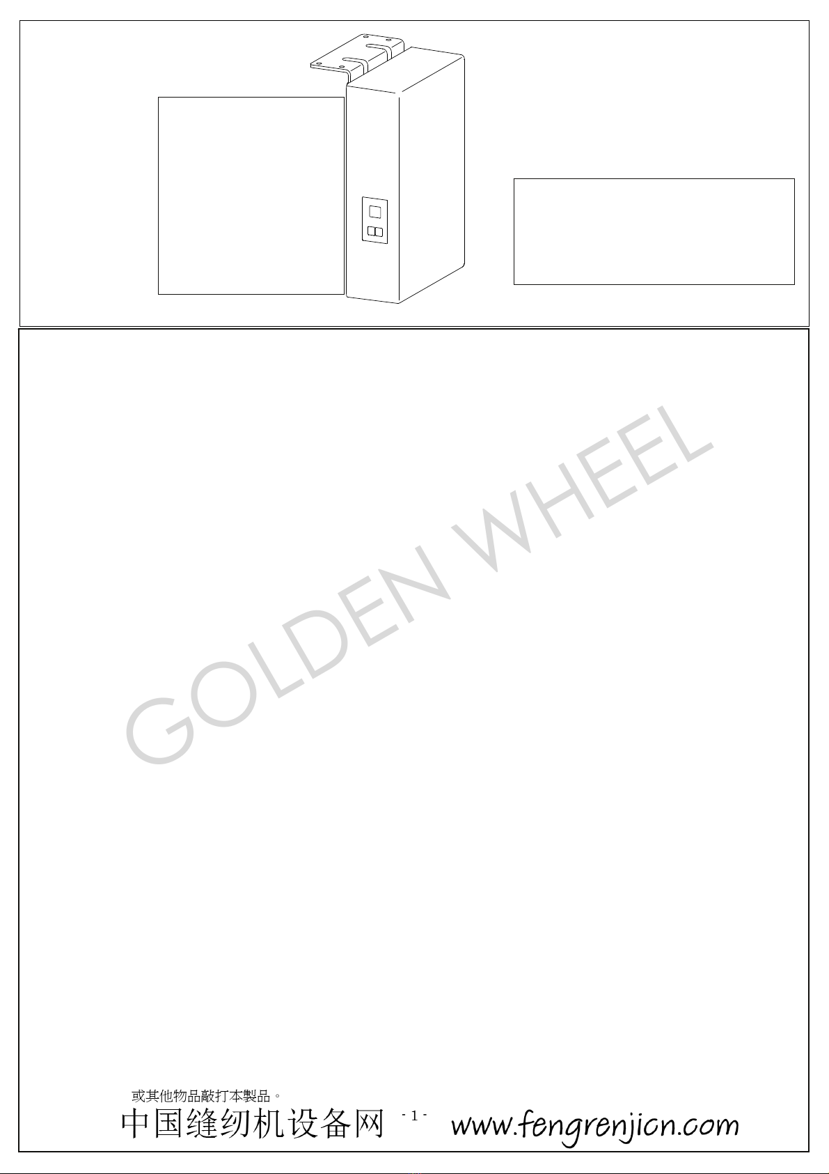
CHEE SIANG INDUSTRIAL M121 Series User manual

INSTRUCTION MANUAL
INSTRUCTION MANUAL
使用说明书
M121系列
为了安全地使用,请您在使用之前仔细阅读本使用说明书。
另外,请您注意保管本使用说明书,以便随时查阅。
Read safety Instructions carefully and understand them before using.
Retain this Instruction Manual for future reference.
No:M121A01
No:M121A01
GOLDEN WHEEL
- 1 -
M121
1
2
3
4
5
6
GOLDENWHEEL
CHEESIANGINDUSTRIALCO., LTD
24248
32
Tel886-2-22999518 Fax886-2-22999519
No.M121A01
1. Safety Precaution
Please read this manual carefully, also with related manual for the machine head before use.
For perfect operation and safety, installing and operating this product by trained personnel is required.
Turn off the power, unplug the cord and wait 10 minutes before any installing, mounting, or opening the control box cover.
This product is designed for use with specified sewing machines and must not be used for other purposes.
10%
※Attention
Only use Power Voltage indicated on the name plate of the M121 in 10 % ranges.
It becomes a cause of malfunction or failure.
20% 80%
3
M121 SERIES INSTRUCTION MANUAL
CONTENTS
1.Safety Precaution
2.Installationand Adjustment
3.Connector Diagram
4.Panel Key Function
5.General Parameter List
6.Error Code / Alarm Code
No.32, Wu Chuan 7th Road, Wu Ku Industrial Area,
Wu Ku Hsiang 24248, Taipei Hsien, Taiwan
Tel:886-2-22999518 Fax:886-2-22999519
※Appear and specification listed in this instruction
manual are subjected to change without notice.
GOLDEN WHEEL

- 2 -
Don’t operate in direct sun light, outdoors area and the room temperature is 40°C above or 5°C under.
Don’t operate near the heater, dew area and the humidity is 20 % less or 80% more.
Don’t operate in dusty, evaporate, combustible gas area, and stay away from corrosive material.
Avoid power cord being applied by heavy objects or excessive force, or over bend.
Power cord must keep 3 cm or above distance to the V-belt and the pulley.
In order to prevent the static interference and current leakage, all grounding works must be done properly.
Turning on the machine in the first time, use low speed to operate and check the correct rotation direction.
During machine operation, don’t touch any moving parts.
All moving parts must use the protective device to avoid the body contact and objects insertion.
Maintenance and repairs must be done by the specially trained personnel.
All spare parts for repair must be approved or supplied by the manufacturer.
Don’t use any objects or force to hit or ram the product.
Danger and caution signs:
Risks that may cause personal injury or risk to the machine are marked with
this symbol in the instruction manual.
This symbol indicates electrical risks and warnings.
GOLDEN WHEEL

- 3 -
2.
2. Installation and Adjustment
.. M121
2.1. M121 Installation
a)M121
a). Install the M121 controller under
the table.
b)
b) Install the pedal to the speed
controlunit of M121 controller.
c)
M121
3
c). The cable of a pedal unit, a motor output,
and a motor encoder is surely
connected to
M121controller.
For details, refer to "3. Connector Diagram".
..
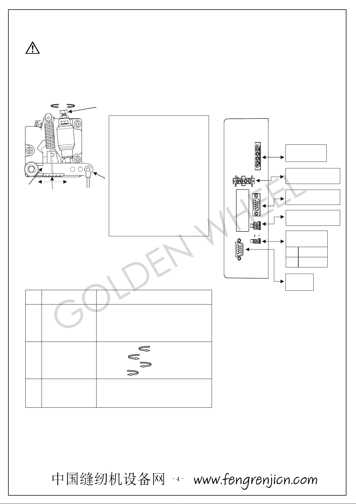
2.2. Install and Adjust The Synchronizer(sensor)
Attention:
When tightening the fixing screws,
release the foot from the pedal.
2
a) Synchronizer Installation:
Mounting the Synchronizer onto the flange of machine
pulley,and match the stopper with a stop groove of the
synchronizer.
With then tighten and secure 2 screws of the synchronizer.
2
b) Synchronizer Adjustment :
Adjust this position with the synchronizer installed onto
the sewing machine and while stopping at the UP
position.
Adjustment of UP Position
Loosen the two screws on the synchronizer joint, and set
thestop position by turning the synchronizer joint.
After adjustment, please fix it by tightening the screws.
sewing machine
motor
p
edal
M121
M121 controlle
r
p
edal
Sewing machine pulley
Flan
g
e
Synchronizer
joint
Synchronizer
Stop
groove
Stopper
(Backside of the sewing machine)
GOLDEN WHEEL
- 4 -
..
2.3. Speed Control Unit Adjustment
Term of ad
j
ustment
Ad
j
ustment result
Toeing forward
force adjustment
Spring A move to right = force increased
Spring A move to left = force decreased
Heeling backward
force adjustment
Bolt B turn= force decreased
Bolt B turn= force increased
Treadle stroke
adjustment
Rod D secure at right = stroke is longer
Rod D secure at left = stroke is shorter
Components of speed control unit :
see figure
A: Spring for toeing forwardforce
adjustment
B: Bolt for heeling backward force
adjustment
C: Treadle / Pedal arm
D: Pitman rod for Treadle / Pedal
B
D
CA
重
Caution :
For person safety, turn off the power switch and remove
the power plug from outlet before any adjustment.
decrease increase
3. Connector Dia
g
ram
MOTOR
AC
AC POWERSUPPLY
SYNCHRONIZER
ENCODER
LIGHT
1 0V
2 +12V
PEDAL
decrease increase
GOLDEN WHEEL
- 5 -
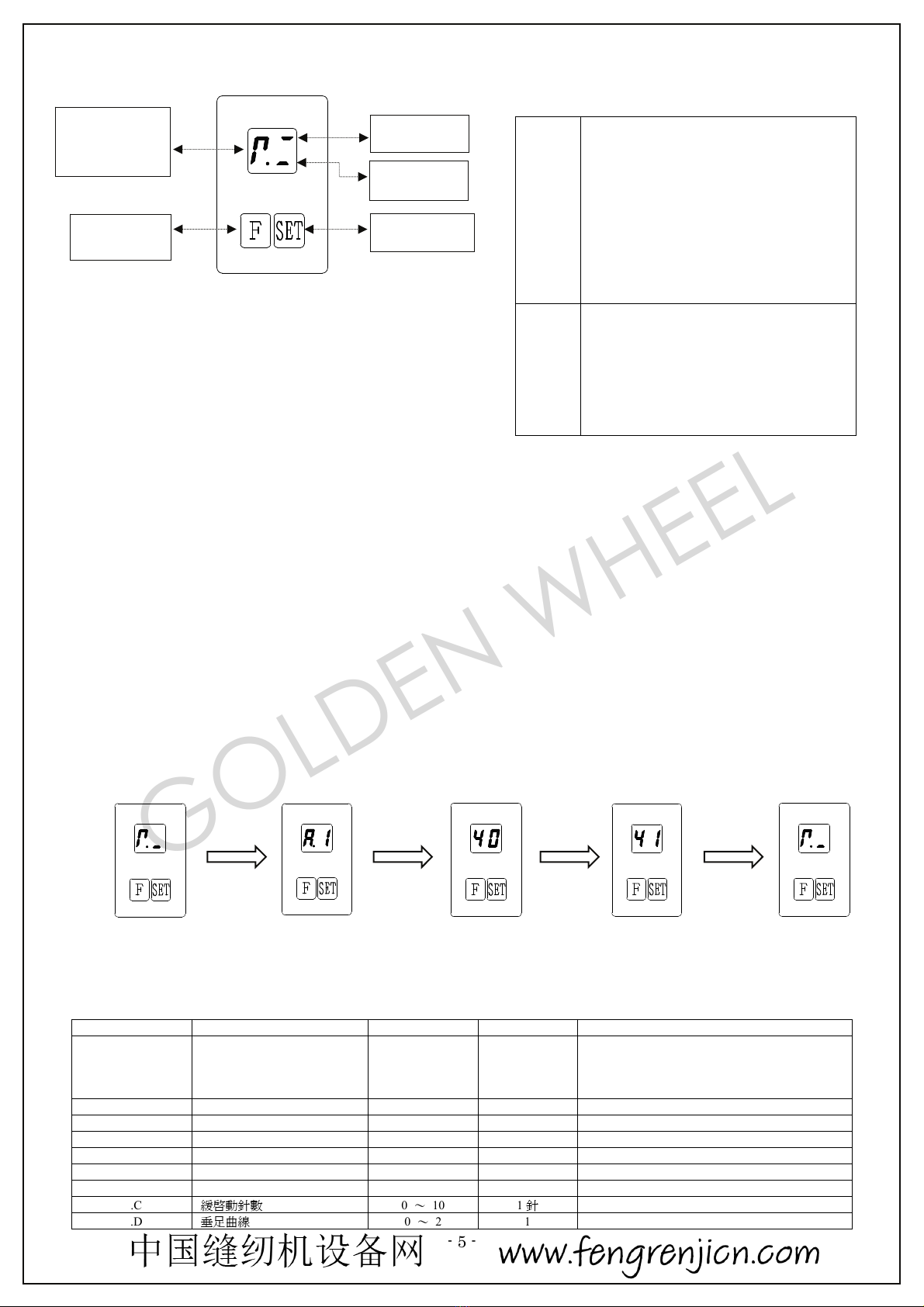
4. PanelKey Function
..
4.1. Parameter Setting Mode
①F
②F
③SET
F
④SET
In parameter setting mode, check and change of each preset value is possible by "Parameter code".
Operation at the parameter setting mode
(1) Press "F" key to enter parameter setting mode.
Display the "Parameter code".
(2) Press "F" key, select "Parameter code" you want to adjust.
(3) Press "SET" key will display selected parameter preset value.
Press "F" key to change the value.
(4) Press "SET" key again, parameter setting mode will be ended and it will return to thenormalmode.
e.g
5. General Parameter List
..
5.1. Parameter A
F
"F" Key
Change to the parameter
setting mode/
Increment "Parameter code"/
Increment parameter value/
Return to normal mode
SET
"SET"
Key
Select "Parameter code"/
Save parameter value/
Changing the needle position
A.1
2 [B.1] 100r/min
B.1
A.2
10
12
A.2 20 A0 10r/min 2
A.5 20 50 10r/min ()
A.6 15 30 10r/min ()
A.8 UP / DN - UP:DN:
A.A ON / OF -
A.B 2 30 100r/min 1
A.C 0 10 1
A.D 0 2 1
Motor rotation
direction icon
Needle
u
p
Needle down
F
Function key
SET
Needle down
Normalmode
「F 」
"F"key 「SET 」
"SET"key
「F 」
"F"key
「SET 」
"SET"key
Normalmode
N
ormalmode
『』
Parameter code
select
Paramete
r
Parameter
settingschange
The function of each key
GOLDEN WHEEL
- 6 -
..
5.2. Parameter B
1 10r/min
21015
10A11B12C13D14E15F
100A0
※1Depending on thesewing machinemodels, the unitof the displayis "10r/min".
2Thenumbersof10-15 is displayed in the alphabet as follows.
10 : A, 11 : B, 12 : C, 13 : D, 14 : E, 15 : F
For example,"100"is"A0".
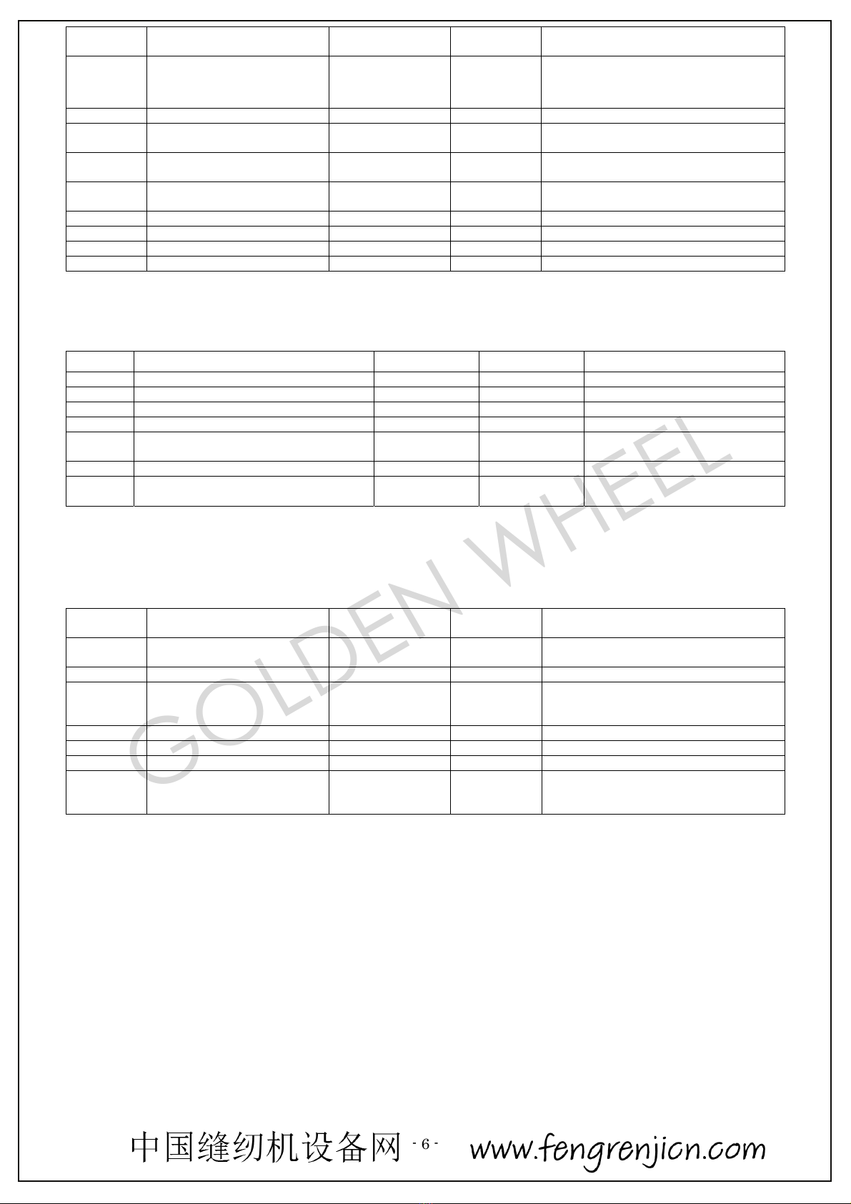
Paramete
r
code Parameter function Range / Selection Unit Remarks
A.1
Maximum sewing speed
2 [B.1] 100r/min
The value of [B.1] is a maximum.
The value of [A.2] is a minimum.
(Digit of 10 of the low-speed setting is not
displayed)1,※2
A.2 Low speed 20 A0 10r/min 2
A.5 The needle up speed by the
backward pedaling 20 50 10r/min (Before thread trimming speed)
A.6 The needle up pre-speed by
the backward pedaling 15 30 10r/min (Thread trimming speed)
A.8 Needle position at
machine stop UP / DN - UP : Up position
DN : Down position
A.A Slow start function selection ON / OF -
A.B Slow start speed 2 30 100r/min 1
A.C Stitch numbers for slow start 0 10 1stitches
A.D Pedal curve 0 21
B.1 2 100r/min 1
B.2 0 / 1 - 0:CCW1:CW
B.3 ON / OF -
B.4 0 / 1 - 0:1:
B.5 0 F0 1 B.3= ON
2
B.6 20 30 10r/min B.3= ON
B.D TS / TK - TS:
TK:
Parameter
code Parameter function Range / Selection Unit Remarks
B.1 Upper limit of maximum
speed
2 Limit of the
machine 100r/min 1
B.2 Direction of motor rotation 0 / 1 - 0:CCW / 1:CW
B.3
Motor stops with a rotation
angle after the needle up by
the backward pedaling
ON / OF -
When it turns ON, machine rotates
automatically after the needle up by the
backward pedaling.
B.4 Direction of rotation of[B.3] 0 / 1 - 0:Reverse rotation / 1:Forward rotation
B.5 Angle of rotation of [B.3] 0 F0 1degree Valid only when [B.3] = ON2
B.6 Speed of rotation of [B.3] 20 30 10r/min Valid only when [B.3] = ON
B.D
Motor running mode at
trimming sequence TS / TK -
TS:Standard operation.
TK:Rotation is not carried outat up stop
position.
GOLDEN WHEEL
- 7 -
6. Error Code /Alarm Code
..
6.1.Error Code List (The error which forced stop of the operation)
When the control box detects an error, forced stop of the motor is carried out.
"Errorcode" is displayed on the panel display.
E01
1 2
E02 IC
1C
E03
E04
E05
AB
E06
E07
E12
E13
E16 uvw
E99
PF
OFF
GOLDEN WHEEL

- 8 -
Erro
r
code Error name Cause of the problem Status and Measurement
E01
Moto
r
over-current
Wiring on the motor short-circuited.
The load torque of the sewing machine istoo
large.
Wiring of the motor has disconnected one or two.
Please check wiring on the motor.
Please check the sewing machine.
E02
Motor control IC
over-current
Motor control IC detects Motor ove
r
-current.
Wiring on the motor short-circuited.
The load torque of the sewing machine istoo
large.
Please check wiring on the motor.
Please check the sewing machine.
E03 Rise of power
supply voltage
When Power ON, detected high voltage.
Connect the wrong voltage, too high.
Please check the AC power. (Too high)
Please check the main board.
E04 Drop of power
supply voltage
When Power ON, detected low voltage.
Connect the wrong voltage, too low.
Please check the AC power. (Too low)
Please check the main board.
E05
Abnormalities in
the encoder signal
The connector of the encoder is not inserted
completely.
The signal wire of the encoder is disconnected.
Please check the encode
r
or encode
r
connectors
and its connection.
Make surethat there is noabnormality in the
encodersignal.
E06
Motor
disconnection
Bad connection at the motor connector.
The connector of the motor is not inserted
completely.
Please check the motor or motor connectors and
its connection.
E07
Synchronize
r
(sensor) signal
error
Can not detect synchronizer signal.
Machine locked or object stuck in the motor
pulley.
Sewing material is too thick.
The connector of the synchronizer is not
Inserted completely.
Please check the synchronizer(sensor) or
synchronizer connectors and its connection.
Please check the synchronizer (sensor) and its
signal.
Please check the machine head to see if objects
stuck in the motor pulley, or rotate not smoothly.
E12
Initial magnetic
pole detection
error
When magnetic pole detection signals are
abnormalities at the time of the Power ON.
The connector of the encoder is not inserted
completely.
Wiring of an encoder is disconnected.
Please check the encode
r
or encoder connectors
and its connection.
Please check that there are no abnormalities in
the magnetic pole detection signal.
E13
pulley ratio
calculation error
Calculation of the pulley ratio is not completed
normally.
The upper position signal has abnormalities.
The upper position signal was disconnected.
Please check the upper position signal connection.
Please check that there are no abnormalities in
the upper position signal.
E16
UVW magnetic
pole detection
signal error
The magnetic pole detection signal has
abnormalities.
The magnetic pole detection signal was
disconnected.
Please check the encode
r
or encoder connectors
and its connection.
Please check that there are no abnormalities in
the magnetic pole detection signal.
E99
Memory erro
r
When the read-out values of memoryare
abnormalities at Power ON.
After Power OFF,Power ON again the error will
disappear, but all parameter setup values return to
the initial value.
When the abnormalities in a repetition occur, the
component replacement of a main board is
needed.
PF
Power OFF When Power ON OFF [ Switch OFF ].
When power supply voltage is too low.
Please check whether it is the value with right
AC power supply voltage.
Displaying, when Power OFF is not Abnormal.
When Power OFF at the time of parameter
change is required, it may display (not unusual).
GOLDEN WHEEL

- 9 -
..
6.2.Alarm Code list(Alarm:Release is possible.)
When the control box detects an alarm, "Alarmcode" is displayed on the panel display.
If you want to continue to operate, you need to pay attention to the cause of the alarm.
E50
E54
Alarm
code Alarmname Contents Status How to release alarm
E50 Pedal position
alarm
When the pedal unit is not neutral position
at Power ON.
Cannot operate
during the alarm.
Please return the pedal to neutral
position.
E54
Overload alarm The load of the sewing machine islarge to
the drive capability of themotor.
Please change into a high outputmotor.
Operation is
continuable under
the alarm.
Please stop operation.
If the detected motor currentfalls,
the alarm will be released
automatically.
:
memo:
GOLDEN WHEEL

启翔股份有限公司
CHEE SIANG INDUSTRIAL CO., LTD.
No.32, Wu Chuan 7th Road, Wu Ku, Wu Ku District 24890,
New Taipei City, Taiwan.
GOLDEN WHEEL
This manual suits for next models
1
Other CHEE SIANG INDUSTRIAL Sewing Machine manuals


