Chemtech Scientific DUOSEAL 1405B-01 User manual

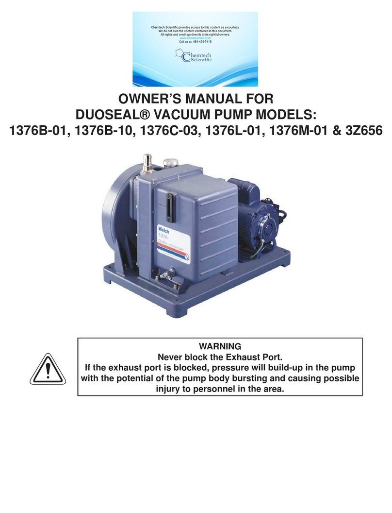
OWNER'S MANUAL FOR
DUOSEAL® VACUUM PUMP MODEL:
1405B-01
Manufactured in an
ISO 9000
Registered Environment
WARNING
Never blocktheExhaust Port.
If the exhaust port is blocked, pressure will build-up in the pump
with the potential of the pump body bursting and causing
possible injury to personnel in the area.
Gardner Denver, Inc.
Welch Vacuum Technology
5621 W. Howard Street
Niles, IL 60714
Phone: (847) 676-8800
Fax: (847) 677-8606 Technical Support (847) 588-2366
E-Mail: gdwelchvacuum@gardnerdenver.com Part No. 67-2061R1.0
Printed in USA
SAVE THESE INSTRUCTIONS
(505)872-0037
idealvac.com

INSTRUCTION
WARNING AND CAUTION
PLEASE READ BEFORE OPERATION
While reading your manual, please pay close attention to areas labeled:
WARNING AND CAUTION.
The description of each is found below.
These units confirm to the SI International system of units of measurement.
The following symbols (with recommendation of IEC1010 ) of warning will be found on the pump.
2
Caution - refer to accompanying documents
Caution - risk of electrical shock
Caution - hot surface

TABLE OF CONTENTS
Section Page
Section 01 Installation
1.10 Introduction 4
Section 02 Operation
2.10 Starting Procedures 6
2.20 Operation and System Optimization 6
2.21 High Pressure Operation 7
2.22 Gas Ballast Principles and Usage 7
2.23 System Leaks - Impact and Detection 8
2.30 Shutdown Procedure 8
Section 03 Maintenance
3.10 Vacuum Problems 9
3.20 Oil Changes and Oil Level 10
3.30 Shaft Seal Replacement 10
3.40 Repairing Oil Leaks 11
3.50 Repairing Vacuum Leaks 11
3.60 Drive Problems 11
Section 04 Trouble Shooting Guide
4.10 Poor Vacuum Readings 12
4.20 Noisy Pump 12
4.30 Excessive Oil Mist 12
Section 05 Quick Reference Chart
Chart 1 13
Chart 2 13
Section 06 Dimenional Drawings (with rotation)
Vacuum Pump 14
Section 07 - Pumping Speed Curves
Speed Curves 15
Section 08 - Exploded Views and Parts Lists
Vacuum Pump 16
Oil Case 18
Section 09 - Accessory Section
Chart 1 19
Chart 2 20
Section 10 - MSDS - Sheets for DUOSEAL® OIL
MSDS-Sheet for 1407K 21-27
3

Section 1:
INSTALLATION
1.10 Introduction
This manual has been complied not only for the care and maintenance of the DUOSEAL pump now in your
possession but as a helpful reference and guide for many problems which are usually associated with mechanical
vacuum pumps. Take time to read these instructions carefully and preserve this manual for future reference; we
think it will be useful to you.
1.11 Unpacking
Carefully remove the pump from the shipping case and unfasten and remove the wooden skid. Preserve all paper
work and inspection tags for future reference. If damage has occurred from shipment a claim must be filed with
the carrier immediately; preserve the shipping container for inspection by the carrier. If you are required to
communicate with your dealer or with Welch Vacuum be sure to include your order numbers for quick
identification. Do not return the pump to the factory without firstcompleting the on-line request form for returned
goods authorization at www.welchvacuum.com.
1.12 Pump Mounting
1.121 Mounted Pumps
Rubber bumpers are supplied with most of our mounted pumps, either loosely or attached. Bumpers are excellent
for applications involving a semi-flexible surface such as a bench top; they help to isolate noise and eliminate
creeping. For more rigid requirements, the pump base may be bolted directly to a firm foundation with or
without the bumpers. All DUOSEAL pumps should be mounted in a horizontal plane.
1.122 Unmounted Pumps
If you have purchased an unmounted pump, refer to parts list for information concerning the motor, motor
pulley and belt necessary to drive your particular pump at the recommended speed.
1.13 Pump Location
The pump should be located preferably in a clean and well ventilated area and adequate space should be provided
wherever possible for routine maintenance such as changes of oil and belt adjustments and replacements. Above
all, the pump should be located as closely as possible to its system in order to utilize it most efficiently. Its
location should include such determining factors as the length and size of connections, the number of bends and
the type of exhaust connections.
1.14 Exhaust Provisions (See Accessory section in back of this manual.)
Exhaust connections will be determined by the type of system to be exhausted and the desired cleanliness of the
atmosphere surrounding the pump. Under normal conditions of mild evacuation nothing more than the dust cap
will be necessary to cover the port. Where relatively high gas flows are involved or where the presence of oil
vapor is objectionable an exhaust filter may be fastened to the exhaust port in place of the dust cap. The exhaust •
filters used on our pumps are capable of absorbing and restricting any vapor particle larger than 0.1 micron.
WARNING
Never block the Exhaust Port.
If the exhaust port is blocked, pressure will build-up in the pump
with the potential of the pump body bursting and causing
possible injury to personnel in the area.
Where extreme exhaust conditions are encountered it is best to pipe the exhaust direct out of the building.
Welch recommended wire reinforced PVC, metal pipe or thick walled rubber hose be used as exhaust lines to
avoid potential of line becoming crimped or collapsing resulting in the exhaust port being clocked.
Be sure to call Welch technical service prior to start-up at 847-676-8800 if you have any questions.
4

1.15 Electrical Power
1.151 Power Source Review
Review the power source and the motor rating to be sure they agree in voltage, phase and frequency. On
three-phase applications the direction of rotation of the motor must be considered. Make a momentary check
rotation at the time of power installation and wiring. Momentary backward rotation of the pump is not harmful.
Check the layout drawings for proper direction of rotation.
CAUTION
Make certain the power settings on the pump match your power
source before attempting to operate the pump
1.152 Overload Protection
Motor thermal overload protection is made available by the motor manufacturer as an aid to minimizing motor
failure. Overload protection is a standard feature on all single-phase 60Hz motors. Single-phase motors will
normally have automatic overload protection. Motors of 1-1/2 horsepower or larger supplied with DUOSEAL
pumps contain no overload protection. Installations of such equipment must comply with local electrical codes
which dictate appropriate starter and protection devices. It is strongly suggested that you familiarize yourself
with the protection supplied with your motor so that you may react accordingly in the event of an emergency.
Automatic reset protection is designed to reset itself after a predetermined cooling period. If the fault to the drive
remains unaltered, the motor will cycle on and off until the fault is corrected. The motor data plate will indicate
the presence of thermal protection.
1.16 Vacuum Connections (See Accessory Section in back of this manual.)
1.161 Choice of Connections
The choice of connections and fitting can have a very marked effect on the pumping speed at the vacuum
chamber. Any connection placed between the pump and the chamber creates an impedance to the flow of gas.
This is particularly true at low pressures in the millitorr range where the gas flow is substantially molecular
in character. The gas flow is then dependent upon the kinetic activity of the molecules to bring it to
the intake of the pump.
1.162 The Effects of Conductance
It has been shown that the conductance of a tube is proportional to the cube of its radius and inversely
proportional to its length. Therefore it is imperative that the connecting lines be as large in diameter and as short
in length as practical. For best results the diameter of the connecting tube should be at least as large as the
diameter of the pump intake. To avoid a large reduction in pumping speed at the vacuum chamber, it is clear that
the conductance of the line must be considerably greater than the speed of the pump.
1.163 Metal Joints
If metal piping or tubing is used, it is preferable to solder or braze all of the connections. Where threaded joints
must be used, coat the threads with LocTite® Thread Sealant with Teflon®, or Leak Lock and screw together
tightly. Flanged connections with elastomer gaskets make excellent demountable joints. Modular vacuum piping
and fittings are now extensively used.
1.164 Rubber Tubing Joints
Where metal tubing is used between the system and the pump intake, joints can be make by butting the ends of the
two sections together in a short section of vacuum hose.Worm-screw band clamps are useful for securing the hose
to the tubing.Whatever the joint you choose to use, cleanliness should be of utmost importance.
1.165 Valves and Stopcocks
Metal valves or stopcocks may be used in the connecting line between the system and the pump to provide a
means of isolating the pump from the system. To minimize the impedance of flow, the valve openings should be
as large as possible. Lubricate the rotating plug of the stopcock with a film of vacuum grease sufficiently thick
enough to prevent seizure.

1.17 Traps (See Accessory section in the back of this manual.)
1.171 The need for a Trap
Where corrosive vapors or large quantities of condensable vapors are evolved from vacuum processing, a cold
trap may be used in the connecting line to the pump. It will help prevent damage to the pump mechanism and
reduce oil contamination. The cold trap, immersed in a suitable Dewar flask, is installed to that the vapors may
come in contact with the surfaces of the trap and condense. Commonly used refrigerants are liquid nitrogen or
dry ice and acetone. The refrigerant to be used depends upon the freezing point of the contaminations. A variety
of cold traps are available from Welch Vacuum, Thomas Industries, inc.
1.172 The care of a Trap
When using a cold trap the refrigerant should be maintained at a high level in the flask to keep the trap at a
uniformly low temperature. If the trap is re-warmed it may allow re-evaporation of the condensate. The
refrigerant add tube on the liquid nitrogen trap should not be obstructed as the refrigerant boil-off can produce
dangerously high pressures. If the trap becomes saturated it should be disconnected from the system, drained and
cleaned. An increase in pressure in the vacuum system will normally indicate that the trap has become saturated.
To clean the trap, remove the trap from the system, allow the trap to warm up and rinse off the condensate with a
suitable solvent in a fume hood. Thoroughly clean and dry the trap before reinstalling in the system.
Section 2: OPERATION
2.10 Starting Procedures
2.101 Starting a DUOSEAL Pump
Before attaching the pump to a system it is well to familiarize yourself with the function and action of the pump
which you have now required.Remove the intake and exhaust port plugs and temporarily provide a stopper for
the intake and a dust cap for the exhaustReview the power requirements as described in Section 1.4.
CAUTION
Do not run this pump with the intake open directly to
the atmosphere. The pump will overheat, excessive oil mist will
be emitted from the exhaust and the pump will eventually seize.
2.103 Cleanliness
Take every precaution to prevent foreign from entering the pump. A fine mesh screen is provided for this
purpose in the intake passage of all DUOSEAL pumps.
2.104 Oil Level Determination
The amount of oil suitable for efficient and satisfactory performance should be determined after the pump has
reached its operating temperature. Initially, however. the pump should be filled with fresh oil while the pump is
idle. Fill the pump until the oil level falls half way of the oil level window. If after a short period of operation the
level should fall, it is likely the result of oil entering some of the interior pockets of the pump. If the oil level
rises, this signifies oil has drained into the pump cavity while pump was idle. Shut off pump, then drain oil down
to proper level.
If a gurgling sound occurs, additional oil must be added. Mechanical pumps will gurgle in varying degrees under
four conditions of performance: [a] when operating at high pressure as in the beginning cycles of evacuation of a
chamber; [b] when the oil level in the pump reservoir is lower than required; [c] when a large leak is present in
the system; and [d] when the gas ballast is open. Awareness of the possibilities will save time in setting up a
system. Best performance of a mechanical pump is generally obtained after sufficient time has been allowed for
the pump to come to operating temperature.
6

2.20 Operation and System Optimization
2.21 High Pressure Operation
DUOSEAL two-stage pumps are designed to be most efficient when operated at or near their ultimate blanked off
pressure. The pump is designed to remove air from a vacuum system at atmospheric pressure to a deep vacuum.
When the pump is operated at elevated pressures up to about 10 Torr for long periods of time, the pump will run
hotter. At elevated ambient temperatures under these conditions, the thermal protection switch on single phase
motors may cut out. Use of an exhaust filter with coalescing element is required.
Leaky vacuum systems, too large a vacuum chamber for pump size or high gas loads to the vacuum systems
are causes for extended runs of the pump at elevated pressure. If you need additional information, please contact
Welch Vacuum at 847-676-8800, extension 1, for further information and precautions.
2.22 Principle of Gas Ballast
2.221 Effects of Unwanted Vapor
Systems which contain undesirable vapors cause difficulty both from the standpoint of attaining desirable ultimate
pressures as well as contamination of the lubricating medium. A vapor is defined as the gaseous form of any
substance which is usually a liquid or a solid. Water, oil and a mercury vapors are three of the more common
vapors encountered in typical vacuum systems. When such vapors exist in a system, the vapors or mixtures of
gas and vapor are subject to condensation within the pump; the precipitated liquid may thus ultimately dissolve
or become emulsified with the lubricating medium. This emulsion is recirculated to the chambers of the pump
where it is again volatilized causing increased pressure within the system.
2.222 Presence and Removal of Condensate
Condensation takes place particularly in the compression stroke of the backing or second stage of a two-stage
pump. The compression stroke is that portion of the cycle during which the gas drawn from the intake port is
compresses to the pressure necessary to expel it past the exhaust valve. Condensation takes place when the ratio
between the initial pressure and the end pressure of the compression is high, that is, when the mixture of vapor
and gas drawn from the intake port is compressed from a low pressure to high pressure. By adding air though the
gas ballast valve to the mixture of vapor and gas being compressed, the pressure required for delivery past the
exhaust valve is reached with a considerably smaller reduction of the volume of the mixture; this, depending
upon the amount of air added, condensation of the vapor is wither entirely avoided or substantial reduced.
2.223 Pump Function With Gas Ballast
In a pump functioning on a contaminated system and operating without the gas ballast, compression within the
stage takes place in the normal manner until the saturation pressure of the contaminating vapor contained within
the mixture of gas and vapor is reached. The saturation pressure of water vapor is that pressure and corresponding
temperature at which the dew point of the vapor is reached and condensation occurs. The saturation pressure of
water vapor at an ambient temperature of 20°C is 17.5 Torr, while at 60°C, the approximate operating temperature
of a pump, the saturation pressure is 149 Torr. The external side of the exhaust valve is subjected to atmospheric
pressure. Consequently a compressive force somewhat greater than atmospheric pressure is required to open the
valve and permit expulsion of the gas. Sometime during increased compression of the mixture of gas
and
vapors, the saturation pressure of 149 Torr for the water vapor is reached and the vapor condenses. The
condensate is
then allowed to emulsify with the oil which is recirculated within the pump stages this providing continued
contamination of the system.
2.224 Pump Function With Gas Ballast
On the other hand, when ballast air at atmospheric pressure is supplied to the compression stroke by means of the
gas ballast, the partial pressure of the unwanted vapor becomes a very small part of the total pressure of the
mixture of gas, vapor and newly supplied air. The vapor is thus prevented from reaching its saturation pressure
corresponding to the temperature of the pump and is finally expelled form the pump as a vapor.
2.225 Controlled Ballast Flow
Some degree of variation in ballast flow may be obtained by the amount of opening applied tot he gas ballast.
Two or more turns of the gas ballast are sufficient to open it wide. With the gas ballast open, the sound of the
exhaust is similar to that of a pump operating against a large leak. Because of the increased pressure introduced
into the compression stroke, the pump must work a little hard to function, thus resulting in an increased
operating temperature of approximately 8°C over a prolonged period of time. Tests have shown that continuous
and prolonged operation for several weeks under these conditions is not injurious to the pump.
7

2.226 Other Forms of contamination control
The application of the gas ballast is a moderate and very successful method for the removal of condensable
vapors. For very heavily laden systems, other means of removal such as oil separators may be required.
For mild cases of contamination the simple expedient of a cold trap or a change of oil serve the purpose.
2.23 System Leaks - Impact & Detection
2.231 Large Leaks
The importance of eliminating all leaks in a vacuum system is obvious when it is realized that a leak into the
system, at atmospheric pressure, expands in volume by a factor of 750,000 to 10,000,000 or more. The pump
must remove this added volume to maintain the desired vacuum. Fortunately a number of effective techniques
for leak detection have been developed. Large leaks can be located by pressurizing the system and painting the
suspected area with a thick soap solution. Escaping air will produce soap bubbles.
2.232 Small Leaks
Small leaks may also be detected by spraying a suspected area with acetone or gases rich in hydrogen, and
observing a sudden change in pressure on an electrical gauge. The difference in calibration of these gauges, for
air and other gases, will produce a distinct change in the pressure reading. To use this method of detection, the
system must be under vacuum and the gauge sensing tube must be located between the pump and the area to be
probed. Use extreme caution, as these materials are highly flammable!
2.233 Fine Leaks
Locating very fine leaks requires a helium-sensitive, mass-spectrometer leak detector.
This instrument will locate leaks which cannot be detected by any other method.
Numerous fine leaks can have the total effect of a large leak.
2.30 Shutdown Procedures
2.301 DuoSeal Shutdown
A few simple precautions are all that is necessary when shutdown is in order. If a gauge is connected to the
system, first isolate the gauge, then turn off the power and open the system to atmosphere. If the pump is
removed from the system, cover the intake port with a rubber stopper or suitable cover to protect the pump
against contamination and loose particles. If the pump has been contaminated in service and is going to be
shelved for a prolonged period it is best to drain the oil and refill with a fresh charge.
8

Section 3:
MAINTENANCE
3.10 Vacuum Problems
3.101 Pressure Determinations
Leakage, contamination and unusual outgassing are the general causes of problems associated with poor
vacuum. To operate at maximum efficiency a system must be thoroughly clean. If the system is completely clean
and free from leaks, and unwarranted vacuum problems still exist, the pump should be checked. A simple criterion
for the condition of a mechanical pump is a determination of its ultimate pressure capability. This can be
accomplished
by attaching a gauge directly to the pump. The gauge may be any suitable type provided consideration if given
to the limitations of the gauge being used. Refer to Paragraph 1-8 for further suggestions. If the pressure is
unusually high, the pump may be badly contaminated, low on oil or malfunctioning. On the other hand, if the
pressure is only slightly higher than the guaranteed pressure of the pump, an oil change may be all that is required.
3.102 Oil Contamination
The most common cause of a loss in efficiency in a mechanical pump is contamination of oil. It is caused by
condensation of vapors and by foreign particles. The undesirable condensate emulsifies with the oil which is
recirculated and subject to re-evaporation during the normal cycle of pump activity thus reducing the ultimate
vacuum attainable. Some foreign particles and vapors may form a sludge with the oil, impair sealing and
lubrication and cause eventual seizure. A gas ballast calve is helpful in removing vapors, especially water, but it
is not equally effective on all foreign substances; therefore, periodic oil changes are necessary to maintain
efficient operation of the system. The required frequency of changes will vary with the particular system,.
Experiences with the process will help you determine the normal period of operation before an
oil change is required.
3.103 Oil Overheating
This pump is designed to operate continuously below 10 Torr. Continuous operation of this pump above 10 Torr
will lead to overheating and eventual pump failure. See Section 2.21, High Pressure Operation.
3.20 Oil Changes and Oil Level
3.201 Developing a Maintenance Schedule
After studying many examples of pump failure, Welch has found the most common reason is poor condition of
the oil. This is why a regular maintenance schedule for the oil is critical to obtain the longest service life out of
your DUOSEAL pump. Welch recommends that you examine the condition of the oil on a daily basis in the early
days of a new process or experiment. You want to look for discoloration of the oil and whether the oil level is
rising. The discoloration can indicate deterioration of the oil and a rising oil level can indicate condensation of
vapors is occurring in the pump. When changes occur, the oil needs to be change. If no changes in the oil
level or color are observed, extended pump service life is obtained if the oil is changed every three to four
months.
3.202 Forced Oil Flushing
When you drain oil through the drain valve, you are not removing the oil and contaminants that are inside the
pumping mechanism. You are removing oil only from the oil case. Welch recommends a forced oil flush of
DUOSEAL pumps be performed at the regular maintenance oil change.
The procedure for the forced oil flush is given below.
9

3.203 Forced Oil Flushing Procedure
1. Check the oil level, if the oil level is well above the fill mark, (This may indicate either the pump has been
overfilled with oil or has ingested a liquid or a large amount of vapor water or organic solvents.)
Please go to step 2. If the oil level is even with the fill mark and you do NOT suspect corrosive gases or
particulates (hence forth called contaminants) ingested have damaged the mechanism, run the pump for
15 minutes to allow the pump oil to warm up before going to step 2.
2. Turn off motor for the vacuum pump. Drain the oil into a clear plastic container (may need pliers to open
drain valve). Look for contaminations settling to the bottom of container. If you see contaminants, you
will need to repeat step 3 through 5 several times until the oil comes out clear. The oil you drained from
the pump came from the oil case only. There may be contaminants in the pumping mechanism. To
be sure all contaminants have been removed, the pump mechanism needs to be flushed.
3. Make sure the belt guard is installed before proceeding further. Attach a short hose to the drain valve
which runs into a clear plastic container.
4. Flushing the pump is carried out by adding a cup of DUOSEAL vacuum pump oil through the intake port (
IN) while the pump is turned on for 15 to 20 seconds. While adding the pump oil, the palm of your hand
is placed lightly over the exhaust port (OUT). Look for water coming out of the drain. Turn off the pump.
5. Repeat step 4 until clean oil comes out of the drain hose.
6. Close the drain valve and fill the pump with the amount of DUOSEAL vacuum pump oil your pump needs.
7. Plug the intake (IN) port with a rubber stopper. Turn the pump on and run the pump for 10 minutes.
Close the gas ballast.
8. Check the vacuum reading of the pump by connecting a thermocouple gauge tube to the pump's intake.
If the pump is running nearly as good as when it was new, the total pressure reading you will read on
wither of these two gauges will be at least 10 micron.
A simple way to connect the gauge tube to the pump is to run the threaded tip of tube through a hole in a rubber
stopper. Use pump oil as a lubricant for inserting the tube. The stopper chosen should be bigger than the outer
diameter of the intake flange.
3.204 Refilling The Pump
After you are satisfied that the pump has been thoroughly flushed, refill the pump by pouring new DUOSEAL oil
into the exhaust port. Fill to the indicated level and start the pump with the intake closed. A gurgling noise is
characteristic when high pressure air is drawn through the pump. It should disappear quickly as the pressure
within the pump is reduced. If gurgling continues, add sufficient additional oil through the exhaust port until
gurgling ceases.
3.30 Shaft Seal Replacement
To replace the shaft seal of a pump, drain the oil and remove the pump pulley and key. Remove the screws
securing the old seal and pry it loose with a screwdriver or similar wedge, being careful not to mar the surface
of the pump body against which the seal fits. Discard the seal and its gasket, inspect all surfaces and repair any
damages with a fine abrasive stone. Wipe all sealing areas clean and place a film of DUOSEAL oil on both the
shaft and the inside bore of the new shaft seal. Using a new gasket, carefully slide the new seal into position and
center it on the shaft. It is not necessary to apply any sealant to the gasket. Tighten the mounting screws
uniformly and refill the pump with DUOSEAL oil. Follow instructions included in repair kit.
10

3.40 Repairing Oil Leaks
3.41 Location, Cause and Effect
Oil leaks may develop wherever two mating faces are sealed with a gasket. Such seams may fail as the result of
deterioration of the gasket material, loosening of the screws caused by temperature variations, or improper care
as the result of previous reassembly. Typical gaskets seams in a mechanical pump are located at the oil level
window, the shaft seal, the oil drain, and the mating faces of such mechanical surfaces as the intake chamber
cover, the oil case, and the exhaust chamber cover. The importance of a gasketed seam is determined principally
by its function. If it is a vacuum seal, the ultimate performance of the pump is dependent upon it. If it is an oil
seal, the pump may be operated satisfactorily for some time without loss of function. Eventually, of course, a
great loss of oil may cause harmful damage.
3.402 Repairing Techniques
An oil seam may be sealed by any of several methods. When an 0-ring is employed, the surfaces of the 0-ring
and its groove should be wiped clean. If the 0-ring is not badly deformed or scratched it may be reused by
sealing with a slight film of vacuum oil or vacuum grease. Thin composition gaskets are generally used for large
irregularly shaped areas. A replacement joint of this type should be thoroughly cleaned of all previous gasket
material and the mating surfaces cleaned of any nicks.
3.50 Repairing Vacuum Leaks
3.501 Surface Preparation
Good Vacuum seals are an essential and important attribute of a good mechanical pump. A good seal is dependent
upon the quality of the mating surfaces as well as the sealant and its preparation. The mating faces should be
carefully inspected for any projections or foreign particles which might interfere with proper mating. Slight
projections such as nicks and burrs are most easily removed by rubbing with a fine abrasive stone. The surface of
the mating parts may be washed with a solvent or alcohol after which they must be thoroughly dried.
3.502 Temporary Repair
Temporary vacuum repairs are often made by covering the known leak with an industrial sealant such as Loctite
with Teflon. Such a practice, however, is not recommended for seals of a permanent nature.
3.60 Drive Problems
If for any reason the pump will not operate, turn off the power and check the fuse and electrical connections.
Then try the power to the motor only by removing the belt. If the motor operates properly try hand-rotating the
pump in the proper direction with the pump intake port open. If both turn freely then replace the belt and check
the belt tension. The tension should be sufficient to drive the pump without visible slippage. Any greater tension
will cause noise and possible damage to the bearings of both the motor and pump. Make certain that both pulley
grooves are clean and free from oil. The pulleys must be fastened securely on their respective shafts, and in
parallel alignment.
1
1

Section 4: TROUBLE-SHOOTING GUIDE
4.10 Poor Vacuum Readings
1. Disconnect vacuum pump from your vacuum system.
2. Obtain 1 gallon of DUOSEAL oil, 1 gallon or larger clear plastic container, clear drain hose
(1/4 inch ID by at least 2.5 feet long), rubber gloves, goggles, apron and pliers.
3. Carry out a forced oil flush (See Section 3.3b) if motor can turn pumping mechanism without
excessive noise. If pumping mechanism cannot be turned by motor, have pump sent into
factory repair center.
4. Check ultimate vacuum with thermocouple gauge. If reading is still unsatisfactory, consult with
Welch Technical Service after checking for leaks in your connections.
4.20 Noisy Pump
1. Locate noise source on your vacuum pump (motor, belt, pump).
2. If motor makes noise:
. Check for loose bolts on motor
mount. . Motor may need to be
replaced
3. If belt makes noise:
. Pulley may be bent. If so, replace.
. Loose belt, tighten by loosening bolts on motor and moving motor away from pump until belt
exhibits a 1/2 inch deflection.
4. If pump makes noise: vanes may be sticking, carry out a forced oil flush.
5. If noise level is still unsatisfactory, consult with WELCH Technical Service at (847)676-8800, Ext. 1.
4.30 Excessive Oil Mist
1. Check oil level. Maintain the level between the two lines on the oil window during operation.
Too high a level will cause excess oil mist.
2. Determine the vacuum level in your system with a thermocouple gauge or manometer.
Be sure the pump is operating at a pressure of 10 Tarr or lower for continuous operation.
3. A system leak(s) or degassing can cause excessive oil mist. Locate and seal the vacuum leaks.
High vapor loads may require a larger pump to compensate.
4. An oil eliminator can be installed for coalescing the oil mist from the exhaust gases. If an oil mist
eliminator is already installed, the element may need to be replaced if saturated with oil.
Open up oil mist eliminator and examine the element; replace if needed.
5. Check the oil condition for any visible change in color or consistency. Contaminants in the oil can
add to the amount of oil exhausted. Carry out a forced oil flush if contamination is discovered. (
See Section 3.3b.)

Section 5: QUICK REFERENCE CHART
Specifications
Free Air Displacement, L/M (CFM)
91 (3.2)
Gas Ballast
Yes
Ultimate Pressure, Torr (mbar)
1 (1.3)x10-4
Rotational Pump (RPM)
525
Oil Capacity, quarts (Liters)
2.25 (2.1)
Net Wt. Unmounted Pump, lb (Kg)
82 (37)
Net Wt. Mounted Pump, lb (Kg)
112 (51)
Tubing Needed (I.D. Inches)
7/16
Standard Flange Size
NW16
Intake Thread Size
1-20
Exhaust Thread Size
1-20
Electrical Requirements 1
115V/230V
Electrical Requirements 2
60Hz
Electrical Requirements 3
1 Phase
Motor Options
1405
Wired for 115V, 60Hz, 1Ph
1405B-01
Wired for 230V, 60Hz, 1 Ph
1405C-01
Wired for 230V, 50Hz, 1 Ph
1405C-02
Wired for 230V, 60Hz, 3Ph
N/A
Wired for 230V, 50Hz, 3Ph
N/A
Replacement Parts
Shaft Seal: Lip Seal
1401E -01
Shaft Seal: Mechanical Seal
1401E
Air Filter Screen
41-0891
Intake Chamber Cover Gasket
41-1308
Oil Case Gasket
N/A
Drain Plug
61-2278
Oil Window
61-2229A
Large Vane
41-1294
Small Vane
41-1294
Large Vane Spring
41-1304
Small Vane Spring
41-1304
Large Vane Spring Holder
41-1303
Small Vane Spring Holder
41-1303
Shaft
41-1293
Upper Exhaust Valve
41-1239
Lower Exhaust Valve
N/A
Pressure Release Valve
N/A
Optional Exhaust Filter
1417P-10
Optional Exhaust Filter
Element
1417G
Pump Pulley
41-2194
Standard Belt
1405A
Standard Hose Barb Fitting
1393J
Standard Flange Adapter
Fitting
1393F
Repair Kits
Minor Repair Kit
1405K-05
Major Repair Kit
1405K-06
Base and Belt Guard Kit
1371A-01
13

Section 6: DIMENSIONAL DRAWING
14

Section 7: PUMPING SPEED CURVES
HIGH EFFICIENCY PUMPING
CHARACTERISTIC OF DUOSEAL®
PUMPS
The low RPM design of DuoSeal vacuum
pumps makes it possible to maintain high
pumping efficiencies into the low micron range.
High RPM direct drive vacuum pumps, on the
other hand, experience a rapid fall off of
pumping speed below 100 microns.
A comparison of the DuoSeal pumping speed
curves shown below, versus high RPM pump
speed curves conclusively illustrates the
superior performance of the DuoSeal pump.
What does that mean for the vacuum pump user?
DuoSeal pumps provide considerable faster
pumpdown time in the low micron range.
15

Section 8: EXPLODED VIEW
16

PARTS LIST
A*: Major Repair Kit Catalog # 1402K-06 B*: Minor Repair Kit Catalog # 1402K-
05 **14010 is a Mechanical Seal Kit-includes Mechanical Seal, Gasket and 3
screws.
+ Item #46 exploded view shown on page 18
17

VIEW AND PARTS LIST FOR MODEL 61-8101
Parts List for Model 61-8101
Item
Qty.
P/N
Description
1
2
61-2229A
Oil Window Glass
2
1
61-2278
Drain Valve
3
2
61-2370
Oil Window Cover
4
1
61-8833
Oil Case, Machined
5
4
62-1014
Screw 8-32x3/8" Flat Head
6
2
66-0304
0-ring #127 Aflas
18

Section 9: ACCESSORY SECTION
Exhaust Filter
Filters oil mist from Filters to 0.3 micron
Easy Replacement Reduces pump noise
pump exhaust particle size
Standard Exhaust Filter
Use with pump model
Dimension
Catalog Number
Diameter
Height
Filter
Replacement
Element
1392, 1399, 1400
1376,1380, 1402,1400
1397,1374
2.5
5
5
2.5
6.25
9
1417
1417P-10
1417P-20
1417L
1417G
1417H-01
Directional Exhaust Filter
Large, high capacity Screw-in type 360 Swivel outlet w/tubing connector
Directional Exhaust Filter
Use with pump model
Dimension
Catalog Number
Diameter
Height
Filter
Replacement
Element
1392, 1399, 1400
1376,1380, 1402,1400
1397,1374
2.5
5
5
2.5
6.25
9
1417L
1417G
1417H-01
1417L
1417G
1417H-01
Exhaust Mist Eliminator
Exhaust oil recyclers capture oil mist expelled from the pump, seperated air from oil, and return collected oil to the pump
via a line connected to the gas ballast inlet. This process effectively reduces oil consumption and minimizes maintenance
requirements by extending the time between oil changes.
Catalog Number
Use with pump model
1416H-01
1400
1416C-01
1405,
1376,
1380,
1400
Requires gas ballast connection kit: Cat. No. 141601 - for models1400,1405,1376,1380,1402
19

Coaxial Traps
Reduces oil back streaming Stainless steel construction Easy Replacement of Element
ISO Size
Capacity
Diameter
Height
A2
Cat.No.1
NW16
to 4 CFM (140 L/min)
3.75
5.25
8.25
541001
Stainless Steel Element for ISO NW 16 Trap 1
541921
Stainless Steel Element for ISO NW 25 and NW 40 Traps1
541922
Cat. No.1. Element must be ordered with trap.
A2. Distance between ISO NW inlet and outlet connections
Dry Ice Cold Traps
Removable 3 quarter center well
for dry ice/alcohol slurry (do not
use acetone)
Visible trapping surface
Available with straight tube connections
Cold temperature up to 12 hours
depending on vapor load
Al. Distance between ISO NW inlet and outlet connections
ISO Size
Diameter
Height I Al 1 I/O Offset
Cat.No.
Repl.Seal Cat.No.
Straight Tube
1/2 O.D.
10.00
8.25 I 10.75
1420H-14
545200
3.5
20
Table of contents
Other Chemtech Scientific Water Pump manuals
Popular Water Pump manuals by other brands

Tsurumi Pump
Tsurumi Pump SQ Series Operation manual

STERWINS
STERWINS 900 JET AUTO-3 Assemby - Use - Maintenance Manual

Gemas
Gemas PUMPEX-80M user manual

MIL'S
MIL'S SIRELLA START-UP AND MAINTENANCE INSTRUCTIONS

Ashland
Ashland SW40 OPERATION, PERFORMANCE, SPECIFICATIONS and PARTS MANUAL

Oase
Oase ProMax Garden Classic 4500 operating instructions