PAC501 Installation Instructions
2
DISCLAIMER
Milestone AV Technologies, and its affiliated corporations and
subsidiaries (collectively, "Milestone"), intend to make this
manual accurate and complete. However, Milestone makes no
claim that the information contained herein covers all details,
conditions or variations, nor does it provide for every possible
contingency in connection with the installation or use of this
product. The information contained in this document is subject
to change without notice or obligation of any kind. Milestone
makes no representation of warranty, expressed or implied,
regarding the information contained herein. Milestone assumes
no responsibility for accuracy, completeness or sufficiency of
the information contained in this document.
Chief® is a trademark of Milestone AV Technologies.
All rights reserved.
DEFINITIONS
MOUNTING SYSTEM: A MOUNTING SYSTEM is the
primary Chief product to which an accessory and/or component
is attached.
ACCESSORY: AN ACCESSORY is the secondary Chief
product which is attached to a primary Chief product, and may
have a component attached or setting on it.
COMPONENT: A COMPONENT is an audiovisual item
designed to be attached or resting on an accessory or mounting
system such as a video camera, CPU, screen, display,
projector, etc.
WARNING: A WARNING alerts you to the possibility of
serious injury or death if you do not follow the instructions.
CAUTION: A CAUTION alerts you to the possibility of
damage or destruction of equipment if you do not follow the
corresponding instructions.
IMPORTANT SAFETY INSTRUCTIONS
WARNING: Failure to read, thoroughly understand, and
follow all instructions can result in serious personal injury,
damage to equipment, or voiding of factory warranty! It is the
installer’s responsibility to make sure all accessories are
properly assembled and installed using the instructions
provided.
WARNING: Failure to provide adequate structural strength
for this accessory can result in serious personal injury or
damage to equipment! It is the installer’s responsibility to
make sure the structure to which this accessory is attached
can support five times the combined weight of all equipment.
Reinforce the structure as required before installing the
accessory. The wall to which the accessory is being attached
may have a maximum drywall thickness of 5/8” (1.6cm).
WARNING: Exceeding the weight capacity can result in
serious personal injury or damage to equipment! It is the
installer’s responsibility to make sure the structure to which
this accessory is attached can support the combined weight
of the box and all equipment not to exceed:
• Wood Stud: 200 lbs. (90.7 kg)
• Steel Stud: 138 lbs. (62.6 kg)
WARNING: Use this accessory only for its intended use as
described in these instructions. Do not use attachments not
recommended by the manufacturer.
WARNING: Never operate this accessory if it is damaged.
Return the accessory to a service center for examination and
repair.
WARNING: Do not use this product outdoors.
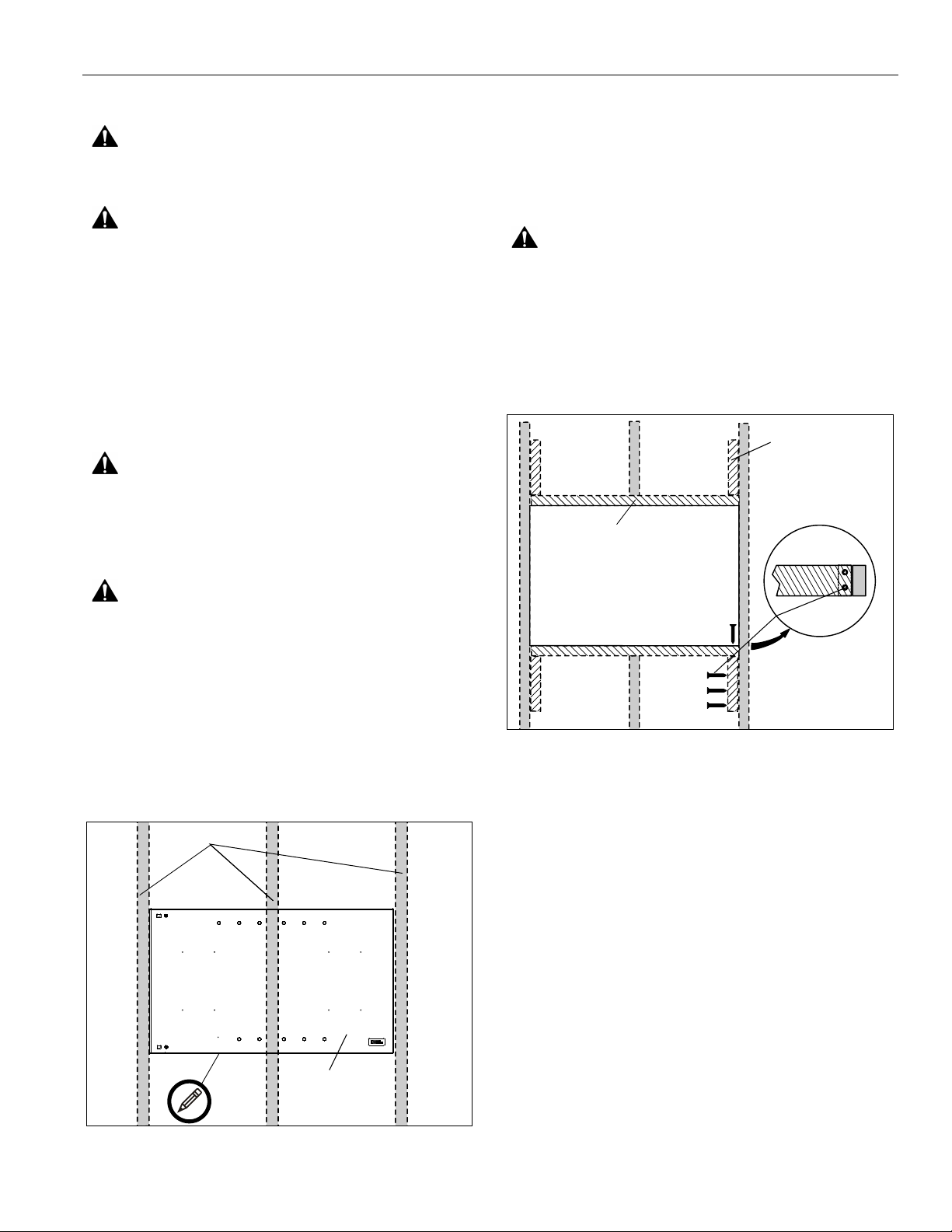
NOTES:
• It is the installer’s responsibility to ensure that the
enclosure is bonded to the ground in the switch box,
in accordance with the National Electric Code,
ANSI/NFPA 70 or Canadian Electrical Code, CSA
C22.1. A green grounding screw is provided in the
enclosure for the purpose, if required.
• The equipment shall be installed and assembled by
qualified service personnel.
• Spacings - To ensure safe operation of the
equipment installed in the enclosure, per National
Electric Code ANSI/NFPA 70, a minimum
separation between power cords and signal or
communication cables may be required.
• This Cabinet System accessory is for use with
Listed wall mounting systems. Refer to the
individual mounting system’s installation instructions
for compatibility.
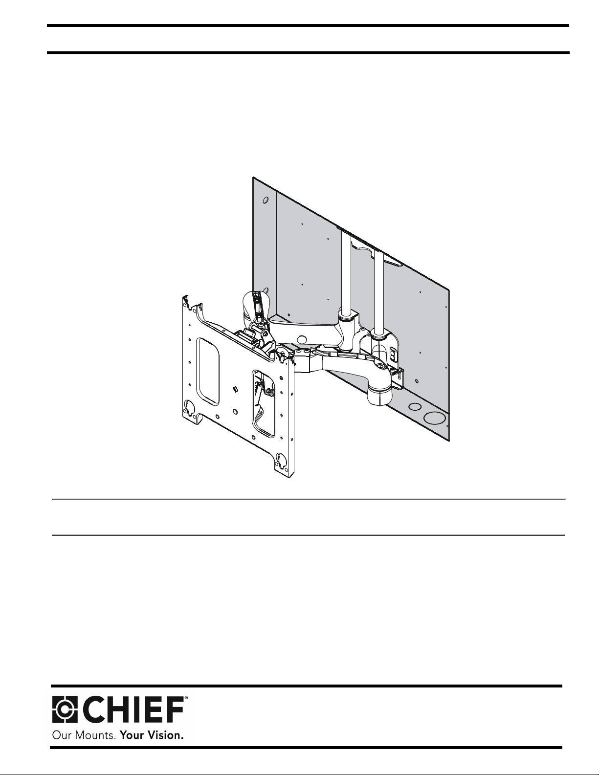
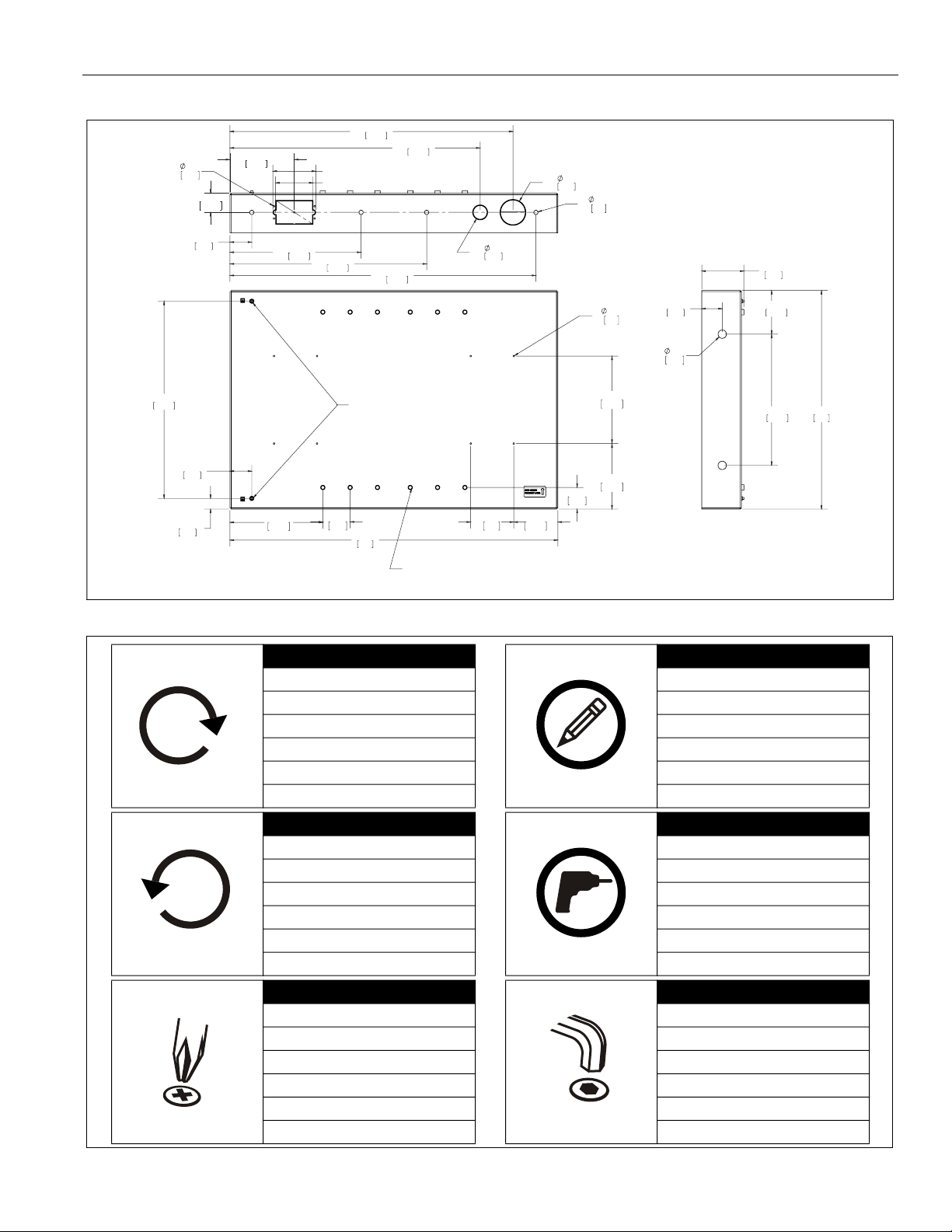
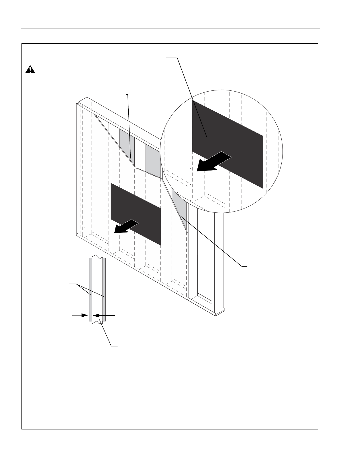
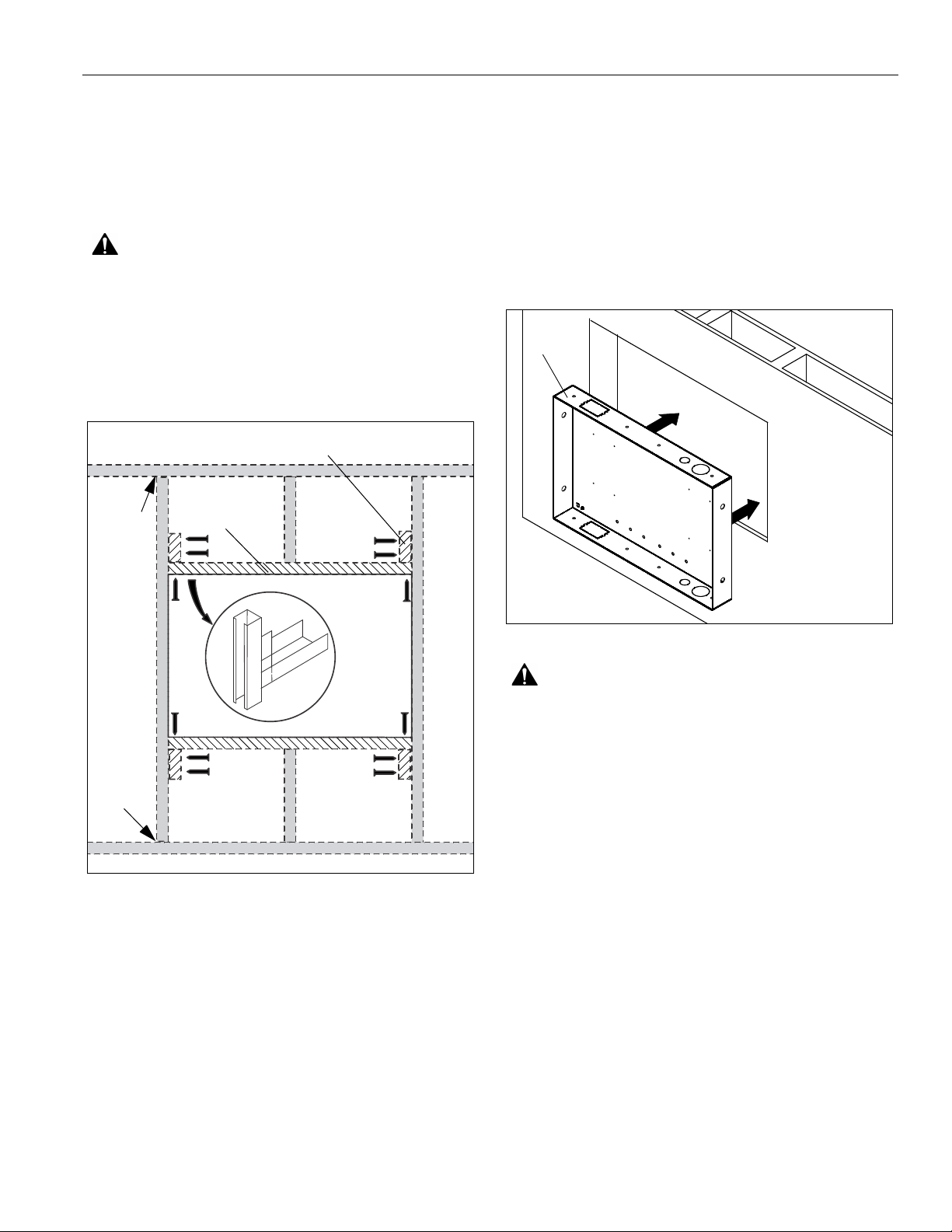
IMPORTANT ! : The PAC501 is designed for in-wall
installation spanning three wood or steel studs 16" on center,
and is to be used with a Listed Chief PNRIW Series large in-
wall swing arm wall mount (not included).
NOTE: The PAC501 has been designed to accommodate two
UL Listed electrical box accessories (not included).
--SAVE THESE INSTRUCTIONS--


 user manual")