Page 7 of 40
Bulletin 441G
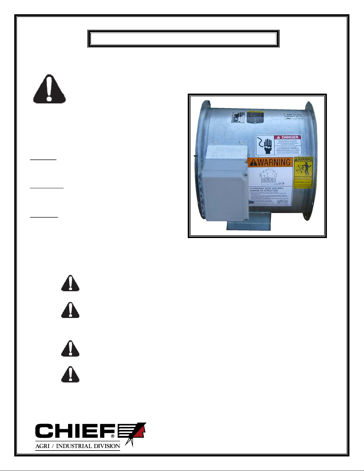
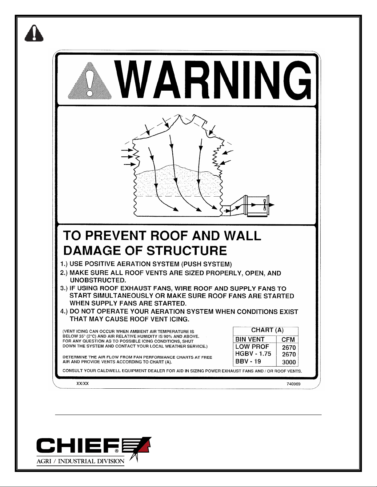
Fi
ure 1 . Warnin
Label Locations
Safety Notice - Important - Read This!
Safety Alert Symbol
This symbol means ATTENTION! BE ALERT! YOUR SAFETY IS AT STAKE!
The Safety Alert Symbol identifies
important safety messages in this document
and on your fan. Make yourself familiar
with the messages identified for you with
the Safety Alert Symbol. When you see this symbol, be alert to
the possibility of serious injury or death. Follow the safety
instructions given in this manual and on your fan.
Signal Words
Danger:Indicates an imminently hazardous situation
which, if not avoided, will result in death or serious
injury.
Warning: Indicates a potentially hazardous situation
which, if not avoided, could result in death or serious
injury and property damage.
Caution:Indicates a potentially hazardous situation
which, if not avoided, may result in minor or moderate
injury. It may also be used to alert against unsafe
practices.
Fan Information:
A.) The unit utilizes electricity as the source of energy. When the power is installed
properly, and protective covers are in place, the unit poses no direct hazard.
WHEN INSTALLING OR SERVICING THE ELECTRICAL COMPONENTS, ALWAYS
SHUT THE POWER OFF AT THE FAN DISCONNECT, AND LOCK THE FAN
DISCONNECT IN THE OFF POSITION, SO NO POWER CAN BE DELIVERED TO THE
FAN WHILE YOU ARE SERVICING THE UNIT.
IN PERFORMING ELECTRICAL CHECKS WITH THE POWER ON, USE A VOLTMETER
AND BE CAREFUL NOT TO CONTACT LIVE PARTS.
B.) The unit, when operating, has a fan blade turning at high speed, and when guarded
with the screen guard, poses no direct hazard.
MAKE SURE THE SCREEN GUARD IS SECURELY FASTENED IN PLACE.
WHEN SERVICING THE FAN BLADE, MAKE SURE THE ELECTRICAL POWER IS
SHUT OFF AT THE FAN DISCONNECT, AND LOCK THE FAN DISCONNECT IN THE
OFF POSITION.