Chiltrix CX34 User manual
Chiltrix Inc. www.chiltrix.com
DC INVERTER
AIR TO WATER HEAT PUMP
For Use with units shipped after 10-12-2018
(If unsure, contact Chiltrix technical support dept. with the serial number)
Installation and Operation Manual CX34-3
Options for Heating, Cooling and Domestic Hot Water
Version 1.9
PLEASE REVIEW ENTIRE MANUAL BEFORE PROCEEDING
PLEASE SUBMIT SYSTEM DRAWING & SCHEDULE A COMMISSIONING
CALL BEFORE STARTING THE UNIT
1

Chiltrix Inc. www.chiltrix.com
Table of Contents
Safety Precautions………………………………………………………………………………………… Page 3
CX34 Components………………………………………………………………………………………… Page 4
Hydronic Piping and Design…………………………………………………………………………… Page 5
Buffer Tanks…………………………………………………………………………………………………… Page 7
Head/Pressure Drop Calculations…………………………………………………………………… Page 8
Using Glycol……………………………………………………………………………………………………. Page 11
Heat Pump Installation………………………………………………………………………………….. Page 12
Valves G1, G2, G3…………………………………………………………………………………………… Page 20
Second Heat Source…………………………………………………………………………………….... Page 25
External T-Stat Control……………………………….………………………………………............ Page 26
System Filling/Purging.………………………………………………………………………………….. Page 28
Using The Controller/Operation.…………………………………………………………………… Page 30
P-Parameter Setting ……………………………………………………………………………………….Page 45
Status/C-Parameter Checking………………………………………………………………………... Page 50
About Screen (Software Version) …………………………………….………..………………….. Page 53
Initial Temperature Settings………………………………………………………………...………… Page 53
Error Codes……………………………………………………………………………………………………. Page 54
Dynamic Outdoor Reset Control ……………………………………………………………………. Page 57
Commissioning and Initial Test Run…………………………………………………………………………… Page 59
Footprint/Placement Dimensions --------------------------------------------------------- Page 60
2

Chiltrix Inc. www.chiltrix.com
IMPORTANT NOTE –MAKE SURE TO PROVIDE YOUR DESIGN DRAWING FOR APPROVAL BEFORE GETTING
STARTED, INCLUDING DESIRED OPERATING TEMPERATURES.
Safety Precautions
NOTE: It is required to read the Safety precautions in detail before operation. The precautions listed below
are very important for safety, please follow all safety precautions.
General
•Make sure that the ground wire in the building is securely connected to earth.
• Wiring tasks should be carried out by qualified electricians only, in addition, they should check the safety
conditions of power utilization, for example, verify that the line capacity is adequate, and the power cable
isn’t damaged.
• Users must not install, repair or relocate the unit. Improper procedures might lead to accidents e.g.
personal injury caused by fire, electrical shock or unit's falling off its base, and water leaking into the
machine. Please contact a professional service department if problems arise.
• The unit shall not be installed at a spot with the potential hazard of leaking flammable gas. If gas is leaking
near the machine, there might be the risk of explosion.
• Make sure that the foundation of the unit is stable. If the foundation is unstable, the outdoor unit may
come loose from its base and cause injury.
• Make sure that the GFCI installed at the service panel is working properly to avoid shock or fires.
• If any abnormity occurs in the unit (such as a burning smell is noticed inside the unit), cut off the power
supply immediately, and contact a professional service department.
• Please observe the follow items when cleaning the unit. Before cleaning, shut off the electric supply of the
unit first to avoid injuries caused by the fan operation.
• Do not rinse the unit with water because the rinsed unit may cause electric shock.
• Make sure to shut off the electric supply before maintaining the unit.
• Please do not insert fingers or sticks into air outlet or air inlet.
Transporting and storage
The machine must be transported and stored vertically at all times
3

Chiltrix Inc. www.chiltrix.com
Hydronic Piping and Design Guide
Installation Methods Heating and Cooling (Heating Shown)
Note: Primary Secondary Piping or Closely Spaced Tees are NOT supported or recommended
for use with this heat pump.
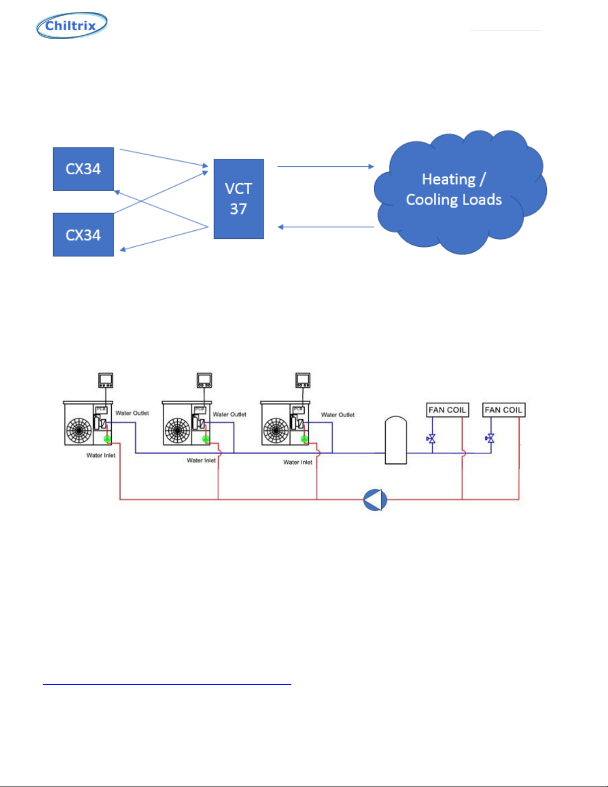
A buffer tank must be used for radiant heating. A multi-port buffer tank such as VCT37 should
be used to combine multiple heat pumps.
An “additional volume” tank must be used when there is less than 15 gallons of total system
fluid volume.
Generic design shown below, not all components shown
Buffer Tank Ducted Air
Handler
Fan Coil
Fan Coil
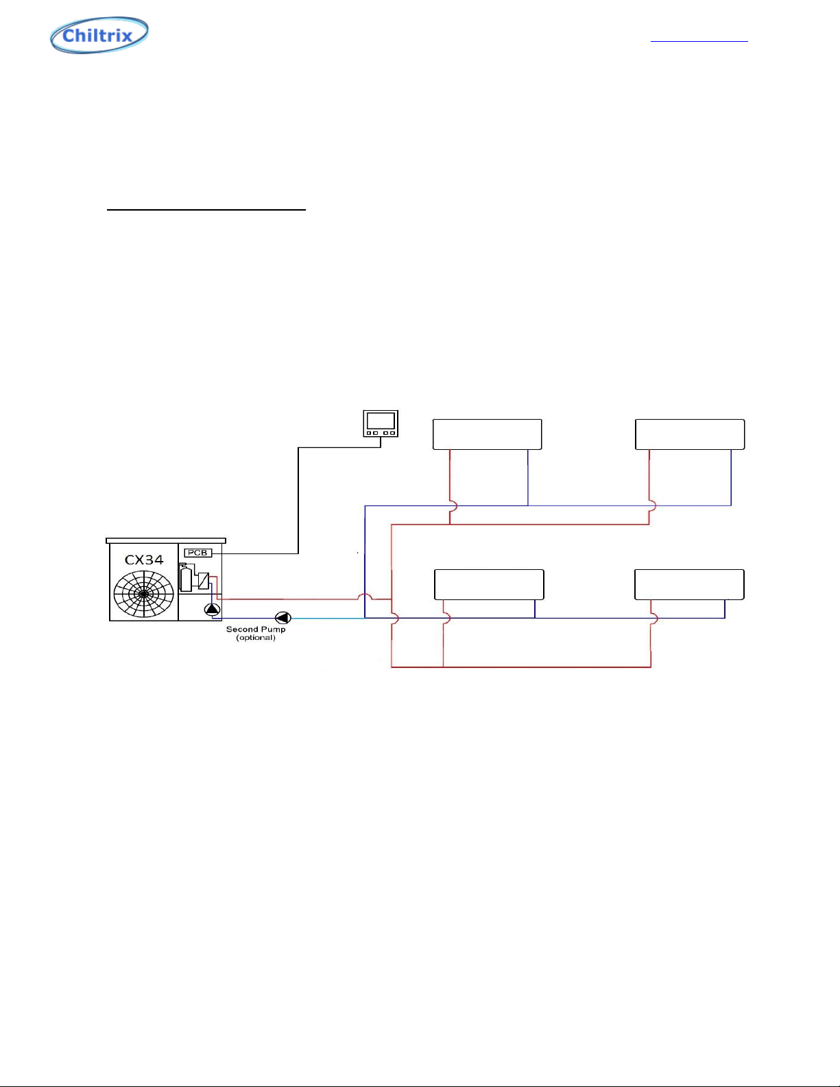
Minimum pipe size should be no less than 1”, CPVC or Oxygen Barrier PEX, reverse return piping is preferable to
assist balancing. Reverse-return will not fully balance multiple chillers as the variable speed pumps may not
always operate at the same speed. The installer should calculate the pipe and fitting resistance to determine the
head pressure. See the examples on the following pages, maximum water flow for the CX34 is 6-7.5 gpm, design
flow is 4.8 gpm. If necessary, a second Chiltrix-provided PWM pump may be added to the loop and controlled by
the CX34. The second water pump connections are always in series with the internal pump. The loop example
above is designed with wild coils (loads). Water flows through the fan coils at all times, if there is a call for heating
or cooling the FCU controls will turn the fan on, adjust fan speed, etc. BTU leakage from a wild coil is around the
same as a light bulb, not enough to worry about. Valved options are available and Chiltrix fan coil units can
support valves, contact Chiltrix support to discuss.
An air discharge valve should be installed at the top of the circulation system, if possible, for easy air discharge. As
an alternative an automatic/manual air vent can be used inline before the pumps.
Always install a water filter or wye strainer on the supply pipe before it enter the heat pump to prevent blockage
of the heat exchanger or pump/flow meter problems.
Do not use CPVC if glycol percentage will be above 25%. Do not use PVC. 5
Chiltrix Inc. www.chiltrix.com
Piping Examples: Stacked Heat Pumps
Preferred Method For 2 or 3 Units:
Optional Method, multiple heat pumps piped in parallel:
(Requires additional loop pump supplied by installer)
PLEASE SEND YOUR PROPOSED FINAL DESIGN TO CHILTRIX SUPPORT DEPARTMENT FOR
APPROVAL, COMMENTS, AND SUGGESTIONS
Pipe Insulation
All loop piping must be insulated per local and national mechanical codes. Any piping in a
system with chilled water (used for cooling) must also be sealed vapor tight to prevent
condensate issues. For design tips and a thickness calculator please visit
http://www.armacell.us/knowledge-center/
6
Chiltrix Inc. www.chiltrix.com
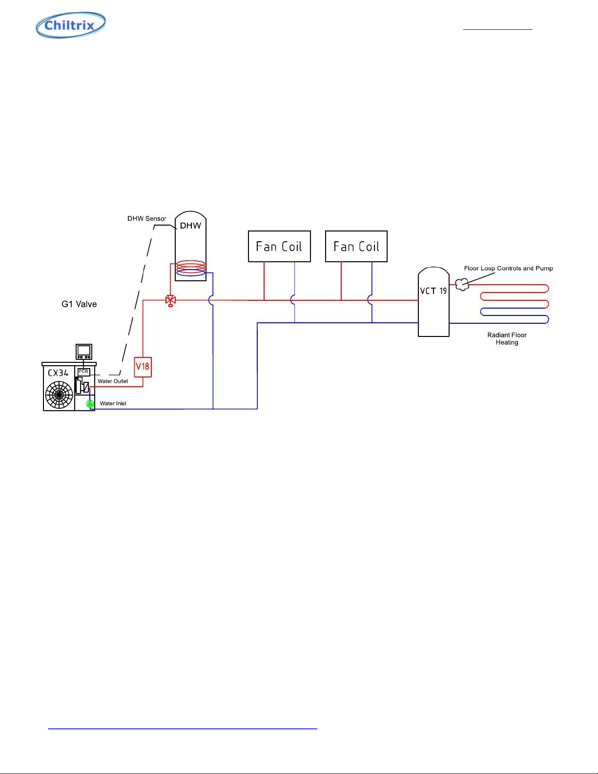
Using a Buffer Tank w/ Radiant
Example below shows optional DHW, optional V18 backup heater, fan coils, and radiant. The radiant is attached
to the load side of a buffer tank.
For V18 information please see the V18 Manual available on the Chiltrix website documents page.
For DHW or buffer tank installation information see the Chiltrix Tank Manual.
Primary / secondary piping is not supported, when connecting to a floor heating loop always use a buffer
tank. Buffer tanks are generally needed only with floor heating with the Chiltrix system, or to combine
multiple CX34 units.
IMPORTANT NOTE ABOUT BACKUP HEAT
Do not ever use buffer tanks for backup heat. The element capabilities of the buffer tank are provided for
emergency heat only. Contact Chiltrix with any questions about emergency or backup heat options. See
Chiltrix DHW & Tank Manual.
The radiant loop pump in the buffer tank drawing is controlled by the customer’s floor loop controls, pump,
etc. The buffer tank isolates the pumps from each other providing hydraulic separation and thermal
buffering.
A 15-20 gallon buffer tank is used generally for best performance with a single CX34. 30-45 gallons is used
for systems of two or three CX34s, and used when multiple CX34s are to be combined. A G3 seasonal valve
may be used to isolate the tank in cooling mode, if applicable, note that isolating the buffer tank in this
manner may cause the need for an additional volume tank to be added.
See more designs here:
https://www.chiltrix.com/documents/chiller-options.pdf
7
IMPORTANT
Check all tank ports including under any element covers
to make sure any unused ports are plugged. Pre-plugged
ports may be only finger-tight. Check ALL ports and plugs
for water tight fit.

Chiltrix Inc. www.chiltrix.com
Head Calculation Example:
To calculate the head pressure for the correct water flow, the pipe length must be measured and all fittings
counted. It is advisable to use flexible red oxygen barrier PEX piping and route it so as to avoid as many elbows as
possible.
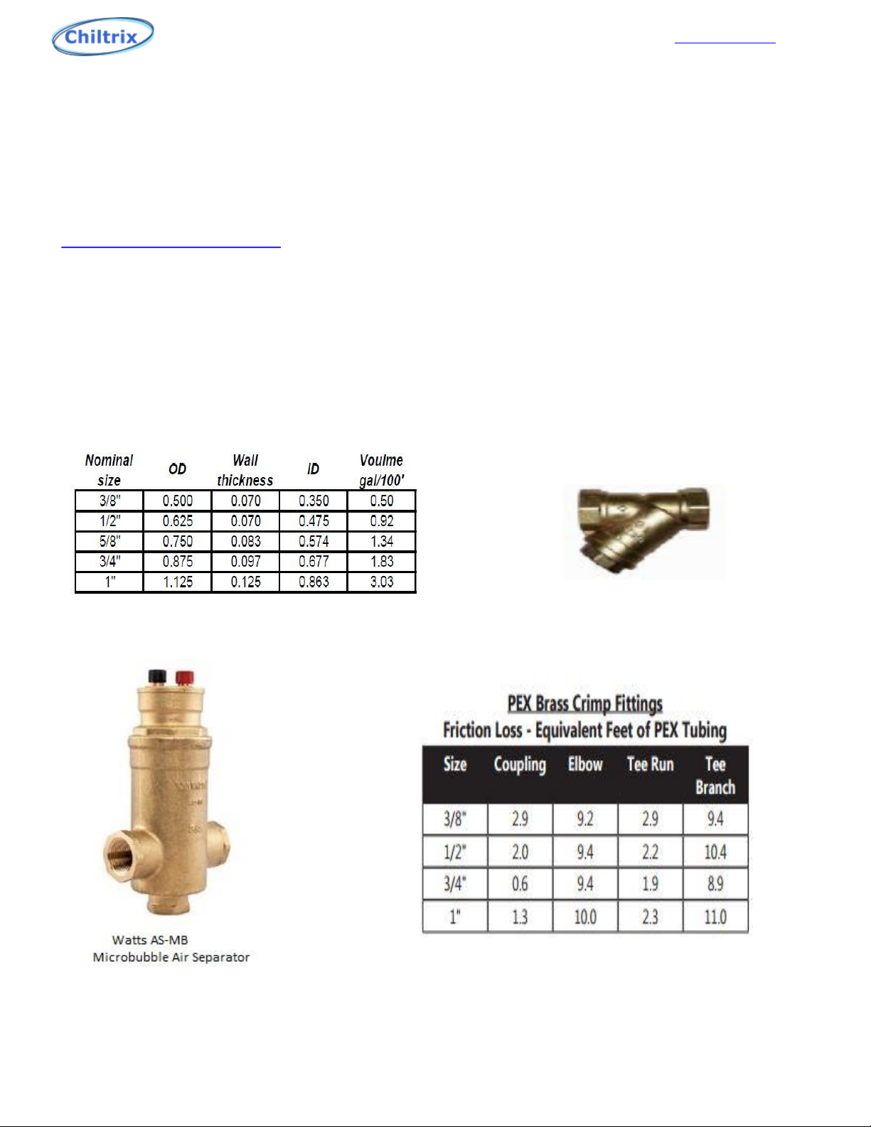
All fittings have an equivalent length of pipe already calculated, available on the next page under PEX Fittings
Pressure Drops. Add up the equivalent length of pipe for the fittings, 13.8’ + 11.7’ =25.5’. Then, add this to the
actual pipe, 25.5’+115” = 140.5’ of 1” pipe. Once you know the total length of pipe, use a (1” PEX 10% Glycol, feet
of head per 100 feet of tubing chart), to get the head for 1’ of pipe, at 40°F and 4.76 GPM. This comes to (.0500)
feet of head per foot. 140.5 x .0500=7.02 ft. of head.
Add up all head calculations, 7.02 + 9.18 + 4.01 = 20.21 ft. of head. Next, we will look at the Wilo Pump curve on
page 13. Maximum head at 4.76 GPM is 23.67 ft.
If using the CX30SE (Free Cooling option) the CX30SE’s pressure drop is 4.5 PSI when active.
8
Chiltrix Inc. www.chiltrix.com
Head Calculations - Continued:
The previously shown example loop has a volume of 4.5 gallons. The internal thermal expansion tank is 2 liters
or .52 Gallons. The volume of the CX34 is 4.5 liters. An additional thermal expansion tank may be required for
larger loops. There are many thermal expansion calculators on the internet, the following is an example.
http://westank.com/calculator/
Minimum loop pressure is 14.5 psi, maximum pressure is 43.5 psi, and ideal pressure is 29 psi. The lowest
temperature is 44°F, the highest temperature is 131°F, the Initial pressure is 14.5 psi, and the final pressure is
29 psi.
A microbubble air separator should be installed in the loop preferably in the higher part of the loop to remove
any air in the circulation loop. Always install a water filter or wye strainer on the supply pipe to the chiller to
prevent blockage of the heat exchanger or damage to flow meter.
WYE STRAINER (from supplyHouse.com)
9

Chiltrix Inc. www.chiltrix.com
Chiltrix CX34 Internal Pump:
Wilo Yonos PARA RS 25/7.5 PWM1 Ku
Head/Ft.
GPM
26.2
22.9
19.6
16.4
13.1
9.8
6.5
3.2
2.2 4.4 6.6 8.8 11 13.2 15.4
Dark Black Line = Chiltrix Pump (25/7.5)
Examples:
If required flow is 4.4 GPM, the maximum allowed head would be 22.9 Ft.
If required flow is 6.6 GPM, the maximum allowed head would be 22.9 Ft.
If required flow is 8.8 GPM, the maximum allowed head would be 18.0 Ft.
Note: The CX34 unit adds max 6 ft. head. A booster pump may be needed for non-optimal
designs, longer piping distances, dual or triple CX34s, other complex or larger systems.
10

Chiltrix Inc. www.chiltrix.com
Glycol
While not always required, customers in colder climates that are subject to occasional freezing should add an
appropriate percentage of food-grade propylene glycol to the system. NEVER USE ETHYLENE GLYCOL.
Ethylene Glycol is a poison. Propylene Glycol is a non-toxic anti-freeze also used in food, cosmetics, etc. and
can safely be used.
Food-Grade Glycol is available at Home Depot and other retailers. You may also consider HSE Corn Glycol
(Biodegradable Food-Grade Glycol made From Corn
https://www.hotspotenergy.com/corn-glycol/
Below is a Freezing Point Chart For Propylene Glycol Mixed w/ Water
NOTE:
When using CPVC piping it is highly recommended
that you do not exceed a 25% glycol to water ratio.
Environmental Stress Cracking, also referred to as
ESC, may occur. Do NOT use PVC piping.
Flow Rates
Required flow rate changes with the glycol %.
Note the “500” formula water factors are adjusted as follows (based on 2,3 tons capacity):
Example:
Based on load calculations a given system need to deliver
a maximum of 31,000 BTU with 30% glycol:
BTU/31,000/480=6.45 GPM
(BTU/water factor=required flow rate)
Use the required flow rate to calculate head based on the Head Flow Curve on the following page.
Minimum pump speed can be set at P53, minimum speed should not produce a flow rate in your system of
less than 6 L/min and generally should not be set lower than 40%. Pump speed can be monitored at C48, 1 is
lowest and 10 is highest speed. Actual water flow can now be monitored on the desktop and at C13, liters
per minute. Test at full pump speed. 1 L/min = .264 GPM // 1 GPM = 3.78 L/min
00% glycol use 500 24,000/500/10=4.8 GPM
10% glycol use 494 24,000/494/10=4.85 GPM
20% glycol use 488 24,000/488/10=4.91 GPM
30% glycol use 480 24,000/480/10=5.00 GPM
40% glycol use 463 24,000/463/10=5.18 GPM
50% glycol use 442 24,000/442/10=5.43 GPM
00% glycol use 500 36,000/500/10=7.42 GPM
10% glycol use 494 36,000/494/10=7.28 GPM
20% glycol use 488 36,000/488/10=7.37 GPM
30% glycol use 480 36,000/480/10=7.50 GPM
40% glycol use 463 36,000/463/10=7.77 GPM
50% glycol use 442 36,000/442/10=8.14 GPM
11

Chiltrix Inc. www.chiltrix.com
Chiltrix Heat Pump Installation
Heat Pump Installation
Installation position
Note: Installation must be carried out by professional personnel.
The recommended mounting pad should be at least 1 ½” above ground level. If you are in an area where snow
occurs, mount the unit high enough above grade to avoid blockage by drifting snow. You can consider a
properly rated wall mount if desired.
Proper drainage is required at the heat pump unit to avoid flooding the outdoor unit with water or ice. Make
sure condensate has a way to rapidly and completely drain away from the unit.
To install the unit on a balcony or on top of a building, the installation site must meet the allowable load
bearing capacity of the building structure without affecting the structural safety. Ensure the unit is well
ventilated; the direction of air exhaust should be kept away from the windows of neighboring buildings.
Adequate service clearance should be kept around the unit. The unit should not be installed in places
accompanied with oil, inflammable gases; corrosive components e.g. sulfur compound, or high-frequency
equipment.
Outdoor Unit Placement / Clearances
(Unit: mm) 200mm = 8” , 350mm =14 “,
400=16”, 500=20”,1000=40”
12

Chiltrix Inc. www.chiltrix.com
Chiltrix Heat Pump Installation
NOTE: The CX34 is shipped with the pump in a separate box attached to the top of the chiller. Please follow
the directions below to install the “C4” Wilo Yonos PARA internal pump.
Internal Pump Installation
(Remove Top, Front, and Right Side Covers) DO NOT BEND OR STRESS
THE PIPING, this may case a broken joint or leak where it joins the heat
exchanger. Cut the insulation and peel it back out of the way of the
flange nuts. This will allow installation of the pump without bending
either of the pipes. The pump will slide in between the pipes with the
washers.
Peel back the insulation Removing the shipping spacer Verify flow direction (UP) Installed properly
13

Chiltrix Inc. www.chiltrix.com
Internal Pump Wiring
If the Wilo RS 25/7.5 PWM pump does not have the required flow rate, a second Wilo RS
25/7.5 may be added to increase the total pump pressure and flow. This will double the
head pressure capability at the targeted flow rate. When adding a booster pump, wire
both power and control wires in parallel with the internal Wilo pump wiring. Use the
same terminals. See diagrams next page.
Electronics Cabinet
14

Chiltrix Inc. www.chiltrix.com
Electrical Connection
General
Note!
Electrical installation and service must be carried out under the
supervision of a qualified electrician. Electrical installation and wiring
must be carried out in accordance with the NEC.
The heat pump must be connected under the supervision of a qualified electrician. Wires, spare parts and
materials etc. must satisfy the relevant standards and codes issued by the host country or region.
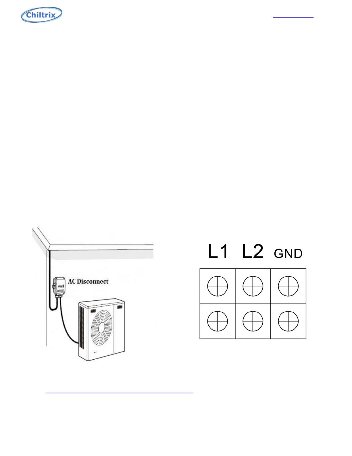
The heat pump does not include an AC disconnect or switch on the incoming electrical supply which will be
required. The power supply cable must be connected to a circuit-breaker with at least a 3 mm breaking gap.
Incoming supply must comply with the technical requirements, with a frame ground wire (neutral is not
used), via a distribution box with breakers. Allowed Voltage range is 208-240vac. Maximum current draw is
13 amps, minimum wire size is 12 AWG, minimum breaker size is 20 AMP. It is advisable to add surge
suppression with transient voltage protection to the circuit powering the chiller.
Main terminal block inside electronics box
Example MOV transient voltage suppressor
https://www.mouser.com/_/?Keyword=V300LA40AP
16


Chiltrix Inc. www.chiltrix.com
When using a second NON-PWM water pump
When using a second NON-PWM water pump, use terminals L2 and C6L for relay coil
power only. Do not connect a pump directly to L2 and C6L, always use a relay with a 240
vac coil. This pump will only run when the PWM pump is running. Setting P54=0 and
P52=1, will shut C6 off when the chiller reaches its set point.
19

Chiltrix Inc. www.chiltrix.com
DHW (Domestic Hot Water)
G1 Valve
G1: DHW/AC / Heating 3-Way Valve
In DHW mode, the G1 valve is powered off. In AC/heating mode, G1 is powered on.
Parameter P08 must be “0” to enable DHW, C19 will show the switch status.
G1 and G3 valves use 220v Primary from the CX34. Use conduit and install per local code.
DHW target setting temperature is the tank water temperature measured with the DHW sensor, not the
CX34 inlet water temperature. If the target temperature is 122°F, (refer to page 43 to set the DHW temp),
and the differential is 2°c, it means, when the DHW tank reaches 122°F, the compressor will stop. When
the DHW tank temperature is lower than 119°F, the compressor will start. See the Chiltrix Tank Manual
before proceeding to install or connect any DHW or buffer tank.
See the Chiltrix Tank Manual for important details and options for using CX34 with DHW, including
backup heat options, and anti-legionella function. READ THE CHILTRIX TANK MANUAL BEFORE
DESIGNING, CONNECTING, CONFIGURING, OR USING DHW.
Note*
There is one sensor taped to the outer CX34 plastic wrapper with the rubber feet, it is for the DHW tank.
The indoor ambient air temp is not used at this time, however, do not disconnect this sensor. Leave all
unused sensors plugged in and wrapped in the bundle above the compressor.
20
IMPORTANT
Check all tank ports including under any element covers
to make sure any unused ports are plugged. Pre-plugged
ports may be only finger-tight. Check ALL ports and plugs
for water tight fit.
Other manuals for CX34
2
Table of contents
Other Chiltrix Heat Pump manuals

Chiltrix
Chiltrix CX34-4 User manual

Chiltrix
Chiltrix CX34 User manual

Chiltrix
Chiltrix CX30FC User manual

Chiltrix
Chiltrix CX50 User manual

Chiltrix
Chiltrix AC series Heating & Cooling series CX30 User manual

Chiltrix
Chiltrix CX45 User manual

Chiltrix
Chiltrix AC series Heating & Cooling series CX30 User manual


