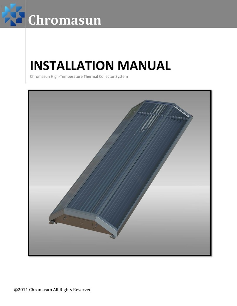
Chromasun High?Temperature Thermal Collector System User manual

©2011ChromasunAllRightsReserved
1.1.1.1
Chromasun
INSTALLATIONMANUAL
ChromasunHigh‐TemperatureThermalCollectorSystem

PVT‐MCT10A‐EN Page|II
AbouttheManual
NOTE:IMPORTANT!Readthisentire
manualbeforebeginninginstallation,
wiring,orusageofthisproduct.
NOTE:Theinstallationofthis
equipmentmustcomplywithall
National,State,andLocalCodes.
NOTE:Bycarefullyreviewingthe
informationcontainedinthis
manual,andfollowingthe
instructionstheriskof:improper
operation,personalinjury,and/or
componentdamagewillbe
minimized.
NOTE:IMPORTANT!Whenindoubt
pleaseaskaChromasun
Representative!
ForTechnicalSupportpleasecall:
+14086344104
HazardIdentification
Warningsandcautionsappearat
appropriatesectionsthroughoutthis
literature.Pleasereadcarefully.
WARNING
Indicatesapotentiallyhazardoussituation
which,ifnotavoided,couldresultindeath
orseriousinjury.
CAUTION
Indicatesapotentiallyhazardoussituation
which,ifnotavoided,couldresultinaminor
ormoderateinjury.Itmayalsobeusedto
alertagainstunsafepractices.
CAUTION
Indicatesasituationthatcouldresultin,
equipmentorpropertydamage.

Page|1 PVT‐MCT10A‐EN
TableofContents
1GeneralInformation................................................................................................................4
1.1BulkPackaging..............................................................................................................4
1.2DomesticShipment......................................................................................................4
1.3SlingKit(RecommendedOption).................................................................................4
2TheChromasunMCTSystem..................................................................................................5
2.1Background...................................................................................................................5
2.2KeyComponents...........................................................................................................6
2.2.1HighTemperatureMicro‐Concentrator(MCT‐HT)............................................6
2.2.2SolarFieldController(SFC)................................................................................8
2.2.3Power,Data,Ventilation(PDV)Interconnects..................................................9
2.3Optional/RecommendedComponents........................................................................9
2.3.1MountLegs(setof2perMCT)(Optional).........................................................9
2.3.2StandClamps(perMCT)(Optional)...................................................................9
2.3.3HeaderPipes(perMCT)(Optional)...................................................................9
3MeasurementsandWeights.................................................................................................11
4Pre‐InstallationChecklist.......................................................................................................13
4.1InventoryCheck..........................................................................................................13
4.2SiteLayoutChecklist...................................................................................................13
5Rigging&Installation.............................................................................................................14
5.1UnpackingtheMCT‐HT...............................................................................................14
5.1.1WoodPallet.....................................................................................................14
5.1.2CollapsingtheWoodPallet.............................................................................17
5.2LiftingandMountingtheMCT’s.................................................................................19
5.2.1PartsList..........................................................................................................20
5.2.2ToolsList..........................................................................................................20
5.3MCTMountingProcedure..........................................................................................21
6MCTPlumbing.......................................................................................................................28
6.1PipingInter‐Connection..............................................................................................28
6.1.1PartsList..........................................................................................................28
6.1.2ToolsList..........................................................................................................28
6.2HeaderConnections...................................................................................................30
7SolarFieldController.............................................................................................................31

PVT‐MCT10A‐EN Page|2
7.1SFCHardware.............................................................................................................31
7.1.1SFCPCBwithExpansionBoard........................................................................31
7.1.2PartsList..........................................................................................................32
7.2SFCFieldWiringSchematic........................................................................................34
7.3Power/Data/Ventilation(PDV)Interconnects............................................................35
7.3.1PartsList..........................................................................................................35
7.4JunctionBoxes............................................................................................................38
7.5SFCExpansionBoardSignals......................................................................................39
8DesiccantVentilationHardware............................................................................................40

Page|3 PVT‐MCT10A‐EN
WhatisIncluded
NOTE:Readingthroughthismanualisa
necessity.TheChromasunmicro‐
concentrator(MCT)High‐Temperature
ThermalCollectorSystemrequiresattention
todetailforinstallation.
NOTE:Theinstallationofthisequipment
mustcomplywithallNational,State,and
LocalCodes.
CoreSystemComponents:
FullyAssembledMCTUnit(s)
SolarFieldController(s)(SFC’s)
Power,Data,Ventilation(PDV)
Interconnects(s)
JunctionBox(es)
Recommended(Optional):
SlingKit
oFourLeggedNylonBridle
MountingKit
oLegStands
oStandClamps
oAllrequiredFasteners
HeaderKit
oSteelHeaderPipes
NOTE:Anymaterialsandworkrequiredto
preparetherooffortheMCTmustbe
providedforbytheinstallingcontractors.
ShippingInspection
AssoonastheMCTarrivesatthejobsite:
Verifythatalloftheunitshavearrived
byinspectingtheshippinglabelsand
comparingthemtotheidentification
dataonthesalesorderandbilloflading
Visuallyinspecttheexteriorofthecrate
andthevisibleareasoftheMCTsfor
signsofshippingdamage
Ifanydamageisfound,theconsignee
shouldindicatesuchdamagebefore
signingthebillofladingand
immediatelyfileaclaimwiththecarrier.
UnitInspection
If,duringunloadingfromthetransport
pallet,jobsiteinspectionrevealsdamageto
anMCT,immediatelyfileaclaimwiththe
carrier.Donotinstallanydamagedparts
withoutappropriateChromasuncustomer
support’sapproval!
Visuallyinspecttheinternal
componentsforshippingdamagesand
formaterialshortagesassoonas
possible.Concealeddamagemustbe
reportedwithin15days
Ifconcealeddamageisdiscovered,stop
unpackingtheshipment.Ifpossible,
takephotosofthedamage.Theowner
mustprovidereasonableevidencethat
thedamagedidnotoccurafterdelivery
Notifythecarrierofdamage
immediately.Requestanimmediate
jointinspectionofthedamagewiththe
carrier.Donotattempttorepairany
partsuntilthedamageisinspectedby
thecarrierandyouhavereceived
instructionsfromChromasuncustomer
service.

PVT‐MCT10A‐EN Page|4
1GeneralInformation
1.1 BulkPackaging
LargeordersofMCTpanelsareshippedinbulkonreusablepallets.TheMCTsareintegralto
theshippingpalletandmustbedisassembledfromthepallettobeunloaded.Additionalparts
accompanytheMCTshippingpalletsinstandardcorrugatedpackaging.
1.2 DomesticShipment
UnitspurchasedwithinNorthAmericawillbeshippedviaaflatbedtruck.TheMCTunitsare
stackedinsetsoffive(5)inreusablewoodenpallets.TounloadtheMCT’sfromthepalletsthe
MCT’smustberemovedoneatatime.Thisisrecommendedtobedonewhentheunitsare
readytobeliftedontotheroof.Foramoredetailedinstructionhowtodothispleasereferto
theUnpackingtheMCT‐HTsectioninthemanual
1.3 SlingKit(RecommendedOption)
ChromasunrecommendstheuseoftheoptionalChromasunSlingKitaccessory.Thefour
leggedbridlednylonstrapkitisdesignedtobeusedwithacranetotransportMCTpanelsonto
theroofbylatchingontotheliftpointslocatedateachcorneroftheMCT.TheSlingKitportion
ofthisinstallationmanualwaswrittenforusewithourSlingKit.Ifyouchoosetonotuseour
SlingKitpleaseconsultanengineerforasafealternativeliftingmethodusingthedatafoundin
theweightandmeasurementsection.

Page|5 PVT‐MCT10A‐EN
2TheChromasunMCTSystem
2.1 Background
TheChromasunHigh‐TemperatureThermalCollectorSystemconsistsoftwo(2)major
components:TheMCTHigh‐TemperatureCollector(MCT‐HT);andtheSolarFieldController.
AnMCTinstallationwilltypicallyconsistofmanySFCunitsconnectedtooneormoreSolarField
Controllers.EachSFCcansupportupto40MCTs(4stringsof10unitseach).
Thesetwocomponentscombinetoprovideanactivetrackingcollectorsystemthatisableto
provideconsistentthermalenergyupto200°C(400°F).
FieldController1
1B
01
1B
02
1B
03
1B
04
1B
05
1B
06
1B
07
1B
10
1B
09
1B
08
JB1
1A
10
1A
09
1A
08
1A
07
1A
06
1A
05
1A
04
1A
01
1A
02
1A
03
1D
01
1D
02
1D
03
1D
04
1D
05
1D
06
1D
07
1D
10
1D
09
1D
08
JD1
JA1
1C
10
1C
09
1C
08
1C
07
1C
06
1C
05
1C
04
1C
01
1C
02
1C
03
JC1
FieldController2
2B
01
2B
02
2B
03
2B
04
2B
05
2B
06
2B
07
2B
10
2B
09
2B
08
JB2
2C
01
2C
02
2C
03
2C
04
2C
05
2C
06
2C
07
2C
10
2C
09
2C
08
JC2
2A
01
2A
02
2A
03
2A
04
2A
05
2A
06
2A
07
2A
10
2A
09
2A
08
JA2
ToBuildingHeating
Load
FromBuildingHeating
Load
TypicalMCTHigh‐TemperatureConcentratingSystemFieldLayout
Legend
1A
10
1A
10
JA1
MCT‐HT
StringJunctionBox
PDVHomerun
HHWSupply
HHWReturn
PDVConnection
Figure1:TypicalFieldlayoutoftheMCT‐HTSystem

PVT‐MCT10A‐EN Page|6
2.2 KeyComponents
2.2.1 HighTemperatureMicro‐Concentrator(MCT‐HT)
TheChromasunMicro‐ConcentratorMCT‐HTisanextgenerationhighperformancesolar
collector.Ithasbeendesignedpurposelyforrooftopintegration.TheMCTislowprofile,
lightweightandhasnoexternalmovingparts;makingitsimpletomountandeasytomaintain.
Usinga20XconcentrationFresnelreflectoroptictheMCTgeneratestemperaturesupto200°C
(400°F)andhasapoweroutputwhichpeaksat2.2kW,dependingonlocation,weather,and
temperature.
TheChromasunMCTisperfectforprocessheatapplicationsandidealforintegrationwith
absorptionrefrigerationandheatpumphardware.
Figure2:ChromasunMCT‐HTpanelsatSCUBensonCenter

Page|7 PVT‐MCT10A‐EN
ReceiverPipe
(SS304A213Tube)
ParallelMirrors
Figure4SchematicofsunlightbeingconcentratedwithinanMCT
Figure3ExplodedviewofanMCT‐HT

PVT‐MCT10A‐EN Page|8
2.2.2 SolarFieldController(SFC)
AChromasuninstallationwillfeatureoneormoreSolarFieldControllers,whichserveasthe
supervisorycontrollertotheindividualMCTunits.EachMCTSFCcanconnectuptofour(4)
stringsoften(10)MCTCollectors,foratotalof40MCTCollectorsperSFC.AdditionalMCTField
Controllerscanbeconnectedtoincreasethenumberofpanelscontrolledinthesystem.
TheSolarFieldControllersacttocontrolthefield,tellingtheMCTswhentoturnonandoffas
wellasprovidingdatalogging,alarm,andfirmwareupdatingfunctionality.
TheSFCtakesinstructionsfromtheexistingbuildingsystem(s)eitherviaanalogsignals(dry
contacts),oroverEthernetusingBacNET,Modbus,orLonWorks.ConsulttheMCTOperation
Manualforwiringandconfigurationdetails.
TheSFCisconnectedtoeachstringinthearraybyfield‐installedconduithomerunsthat
terminateinaChromasun‐providedjunctionbox.Fromhere,eachpanelisconnectedusing
Chromasun‐providedPDVinterconnects.Inthisway,theSFCsuppliespower,dataanddry
ventilationairtoeachMCTitcontrols.

Page|9 PVT‐MCT10A‐EN
2.2.3 Power,Data,Ventilation(PDV)Interconnects
OurPower,Data,andVentilationInterconnectsarerequiredtoprovide,power,data,and
ventilationfromoneMCTtothenext.ThesecanbeseenbelowinFigure5.
2.3 Optional/RecommendedComponents
2.3.1 MountLegs(setof2perMCT)(Optional)
OurMountLegsenableinstallationoftheMCTattherecommendedanglefromaflatbase.A
flatbasebuiltfromUnistrut(orsimilarstructure)isrequired.Themountingportionofthis
manualwaswrittenforusewithourMountLegs.IfyouchoosetonotuseourMountLegs
pleaseconsultanengineerforanalternativemethod.ThesecanbeseenbelowinFigure5and
Figure6.
2.3.2 StandClamps(perMCT)(Optional)
OurStandClampsareusedtosecuretheMountLegsdowntotheUnistrutsection.The
mountingportionofthismanualwaswrittenfortheusewithourStandClamps.Ifyouchoose
tonotuseourStandClampspleaseconsultanengineerforanalternativemethod.Thesecan
beseenbelowinFigure5andFigure6.
2.3.3 HeaderPipes(perMCT)(Optional)
OursteelHeaderPipesaretherecommendedproducttousetoconnecttheplumbingbetween
MCT’s(CarbonandStainlessSteelavailable).TheHeaderPipeportionofthisinstallation
manualwaswrittenforusewithourHeaderPipes.IfyouchoosetonotuseourHeaderPipes
pleaseconsultanengineerforanalternativemethod.ThesecanbeseenbelowinFigure6.

PVT‐MCT10A‐EN Page|10
Figure5:ComponentsfromFrontView
Figure6:ComponentsfromRearView

Page|11 PVT‐MCT10A‐EN
3MeasurementsandWeights
Table1:PhysicalCharacteristics
DimensionsSeeDiagramsBelow
Weight100kg220lb
UnitArea4.23m
2
45sq.ft.
WeightperUnitArea24kg/m
2
4.9lb/sq.ft.
WeightperUnitUnistrut38kg/m28lb/ft
Figure7:MCTCanopyFront,Rear,TopandSideViews

PVT‐MCT10A‐EN Page|12
Figure8:MCTSideView
NOTE:TheMCTangleandcorrespondingheightoftherearlegvarydependingonsitelocation.
Thedesigningengineershouldspecifythepanelangleandthedistancebetweenrows
toavoidshading.TheChromasunMCTDesignManualshouldbereferencedformore
detailedinformation.Forreference,Table2showsUnistrutspacingbasedoncollector
slope.
Table2:AppropriateMCTAngleandLength
MCTLeg
StandModel
Suggested
Angle
(degrees)
Distance
Between
Unistruts
(mm)
Distance
Between
Unistruts(in)
RearLeg
Length(mm)
RearLeg
Length(in)
DimensionA
DimensionBDimensionBDimensionC
DimensionC
0
0
3087 122 0 0
5
5
3075 121 269
11
10
10
3040 120 536
21
15
15
2982 117 799
31
20
20
2901 114 1056
42
25
25
2798 110 1305
51
30
30
2674 105 1544
61
35
35
2529 100 1771
70
40
40
2365 93 1984
78
45
45
2183 86 2183
86

Page|13 PVT‐MCT10A‐EN
4Pre‐InstallationChecklist
4.1 InventoryCheck
Makesurethatalltheunitsarepresent
Checkthecontainerstomakesuretheywerenotmistreatedordamaged
InspecttheMCT’sforanydistortionssuchas:
oShatteredGlass
oCracks
oObviousBends
oCollapsed/BentTerminals
4.2 SiteLayoutChecklist
MakesurethatthereisUnistrutmountedontheroof
ChecktomakesurethepitchbetweentheUnistrutiscorrect
ConsulttheRoofDesignLayoutprovidedbythesupervisingengineerandchecktosee
thatthespacesbetweenbanks(sidetosideaswellasfronttoback)arecorrect
Checktoseethatthelengthofstrutprovidedwillbeabletomounttherequired
numberofpanels

PVT‐MCT10A‐EN Page|14
5Rigging&Installation
5.1 UnpackingtheMCT‐HT
5.1.1 WoodPallet
Step1.
Theshippingpallet.
Step2.
Removethetwotopcrossbarswhichareheld
downby4X2.5”#10woodscrews.(8total)

Page|15 PVT‐MCT10A‐EN
Step3.
Removethetwotrianglepiecesfromoneside
ofthecrateonlytomaintainstructuralstability.
Eachsideisheldinplaceby13X2.5”#10wood
screws.(26total)
Step4.
Removethetworectangularendpieces.
Eachendpieceisheldinplaceby2X2.5”#10
woodscrews.Aswellas2X2”3/8”hexcap
bolts.
Step5.
CranetheMCTunitawaybyconnectingtothe
4liftingholeslocatedateachcornerofthe
MCT.

PVT‐MCT10A‐EN Page|16
Repeatsteps3through5untilalltheMCT’sareremoved

Page|17 PVT‐MCT10A‐EN
5.1.2 CollapsingtheWoodPallet
Step1.
Arrangethepiecesasshownbelow.
Onerowofendpiecesfitnicelyintothe
groovesbetweenthehorizontalslatsinthe
pallet.
Theremaining4endpiecesarearrangedontop
oftheendpiecesalreadyonthepallet,upside
downtointerlock.
Thetwotrianglegussetsarelaiddownontop
oftheendpieces,andthetopcrossbarsare
laiddownontopofthat.
Step2.
ThefinalizedCollapsedWoodPallet.

PVT‐MCT10A‐EN Page|18
Step3.
TheWoodPalletscanbestackedontopofeach
otherwhenreadytobeshippedbackto
Chromasun.
Step4.
ThePalletsreadytobeshippedback.
Other manuals for High?Temperature Thermal Collector System
1
This manual suits for next models
1
Table of contents
Other Chromasun Solar Panel manuals
