CIMCO OXE Series User manual

1
OXE DIESEL SINGLE CONTROL HEAD MANUAL
CONTROL HEAD SINGLE MANUAL
Publication No: ODM1014
DIESEL ENGINE


3
OXE DIESEL SINGLE CONTROL HEAD MANUAL
CONTENT
CONTENTS
Overview_______________________________________________________________________________ 4
About this manual ______________________________________________________________________ 4
Safety information _______________________________________________________________________ 5
Notice to the operator____________________________________________________________________ 5
Safety regulations _______________________________________________________________________ 6
Prior to every use _______________________________________________________________________ 6
During use_____________________________________________________________________________ 7
Aer use ______________________________________________________________________________ 7
Maintenance ___________________________________________________________________________ 7
Safety labels____________________________________________________________________________ 8
Components labels______________________________________________________________________ 8
Other labels____________________________________________________________________________ 8
Description _____________________________________________________________________________ 9
General _______________________________________________________________________________ 9
NMEA 2000® Network ___________________________________________________________________ 9
Control Head ___________________________________________________________________________ 9
Control head overview __________________________________________________________________ 10
Operation _____________________________________________________________________________ 11
Before each use ________________________________________________________________________ 11
First time use _________________________________________________________________________ 11
Single lever control head ________________________________________________________________ 12
Control head operation __________________________________________________________________ 13
Neutral throttle warmup ________________________________________________________________ 15
Low speed control _____________________________________________________________________ 16
Trolling mode _________________________________________________________________________ 16
Lever adjustment ______________________________________________________________________ 17
Station selection and station select protection _______________________________________________ 18
Faults and hazards______________________________________________________________________ 19
Maintenance___________________________________________________________________________ 20
User’s responsibility ____________________________________________________________________ 20
Qualified OXE Diesel Mechanic ____________________________________________________________ 20
Mounting template______________________________________________________________________ 21

4
OXE DIESEL SINGLE CONTROL HEAD MANUAL
OVERVIEW
OVERVIEW
ABOUT THIS MANUAL
This manual provides you with the information you need to know about safely
operating and maintaining your OXE Diesel Control Head. It should be stored on
the boat.
Specifications, operating and maintaining descriptions are subject to change
without notice.
Cimco Marine AB
Metallgatan 17B
SE-262 72 Ängelholm, Sweden
+46 (0)431-371130

5
OXE DIESEL SINGLE CONTROL HEAD MANUAL
SAFETY INFORMATION
NOTICE TO THE OPERATOR
Throughout this publication, Dangers, Warnings and Cautions (accompanied by
the International Hazard Symbol) are used to alert the user to special instructions
concerning a particular service or operation that may be hazardous if ignored or
performed incorrectly or carelessly. Study them carefully!
These safety alerts alone cannot eliminate the hazards that they signal. Strict
compliance with these special instructions during installation, operation, and
maintenance, as well as common sense operation, are important measures to
prevent accidents.
Failure to adhere to these notices may result in the loss of steering and shi/
throttle control, leading to possible ejection from the boat, causing property
damage, injury and/or death.
Symbols and signs
!DANGER
This indicates a hazardous situation which, if not avoided, will result in death
or serious injury.
!WARNING
This indicates a hazardous situation which, if not avoided, could result in
death or serious injury.
!CAUTION
This indicates a hazardous situation which, if not avoided, could result in
minor or moderate injury.
NOTE! Important information.
SAFETY INFORMATION

6
OXE DIESEL SINGLE CONTROL HEAD MANUAL
SAFETY REGULATIONS
SAFETY REGULATIONS
!WARNING
The safety information provided below is intended to inform you of the
dangers that may be present before, during and aer use. It is critical that
you read and understand all the points noted.
!WARNING
The OXE Diesel Control Head system must only be installed by an authorized
dealer or OEM.
Safe operation of the shi and throttle system depends upon proper installation
and maintenance of the system, and common sense, safe judgment, knowledge,
and expertise of the operator. Every installer and operator of the shi and throttle
system should know the following requirements before installing or operating the
system.
If you have any questions regarding any of these warnings, contact your OXE
Diesel retailer.
To reduce the risk of severe injury or death:
1. Always wear a Coast Guard-approved personal flotation device (PFD) and
use an engine shut-off cord (lanyard).
2. Read and understand this manual and the Quick Reference Card provided
with your boat control components.
3. OXE Diesel components are highly engineered and safety tested to ensure
system integrity. DO NOT substitute any component. Substitution with
non-OXE components may compromise system safety, performance, and
reliability.
PRIOR TO EVERY USE
Perform a system inspection as outlined below. See section Operation for further
details.
1. Check your boat’s steering system for proper operation.
2. Inspect all electrical cables for wear, kinks, or leaks.
3. Check for binding, loose or worn shi/throttle control components.
4. Verify proper shi and throttle response for all control levers.
!WARNING
Do not operate boat if any components is not in proper working condition.

7
OXE DIESEL SINGLE CONTROL HEAD MANUAL
DURING USE
1. Wear an, according to local legislation, approved life jacket.
2. Attach engine shut-off cord (lanyard) to your PFD.
3. Never allow anyone not familiar with the operation of the boat control
system to operate the boat at ANY time.
4. Know and adhere to all applicable federal, state, and municipal laws and
regulations that govern boating in your area.
!WARNING
Do not operate the boat if any components are not in proper working
condition.
AFTER USE
No special care is required aer using the control head system. Periodically clean
the control head with a damp cloth and a mild detergent, if necessary.
MAINTENANCE
Maintain your control head system as directed in section Maintenance of this
manual.
SAFETY REGULATIONS

8
OXE DIESEL SINGLE CONTROL HEAD MANUAL
SAFETY LABELS
!WARNING
The labels below should call attention to the possible hazards associated with the equipment shown
later in this manual.
COMPONENTS LABELS
Figure 1-1. Start-In-Gear Advisory Decal, PID#682050.
Figure 1-2. A and B Locator Decal, PID# 682049.
OTHER LABELS
Figure 1-4. Ignition warning decal, PID# 682300.
SAFETY LABELS

9
OXE DIESEL SINGLE CONTROL HEAD MANUAL
DESCRIPTION
GENERAL
The OXE diesel Control Head replaces a traditional cable-operated engine remote
control with an electronic control.
The elimination of mechanical cables to the control head simplifies multi-station
installations, especially when a station is installed onto a flybridge or tower that
is removed for shipping. The system supports the installation of up to two control
heads.
When installing the OXE diesel Control Head, it is recommended to have access to
the OXE diesel Installation Manual.
NMEA 2000® NETWORK
The NMEA 2000® is a CAN based serial network protocol widely used in marine
control systems.
The NMEA 2000® bus contains a backbone connecting all devices, two
terminators, one at each backbone, that reduces interference and dropouts to
each device.
CONTROL HEAD
The OXE Diesel Control Head communicates via the NMEA 2000® bus to the
engine and features status lights, a synchronous trim switch (optional), and
control buttons for additional functions.
DESCRIPTION

10
OXE DIESEL SINGLE CONTROL HEAD MANUAL
DESCRIPTION
CONTROL HEAD OVERVIEW
DUAL STATION/DUAL ENGINE SINGLE STATION/SINGLE ENGINE
1
1
3
3
2
2
1
1
1
3
3
2
2
1
1. Control Head
2. NMEA 2000® helm connectors
3. NMEA 2000® Bus

11
OXE DIESEL SINGLE CONTROL HEAD MANUAL
OPERATION
BEFORE EACH USE
!WARNING
Failure to adhere to these warnings may result in loss of boat control, leading
to possible ejection from boat; causing property damage, personal injury and/
or death.
1. Inspect all electrical harnesses for wear, kinks, or damage.
- Check all electrical harnesses for abrasion, wear, rubbing or chafing.
Check that all connections are tight and free of corrosion.
2. Check for binding, loose or worn shi/throttle control components.
- Check all shi and throttle cables and harnesses for signs of wear,
damage or chafing. Check that all cables move freely and are not binding
or corroded.
3. Verify proper shi and throttle response for all control levers.
- Check that all shi and throttle levers operate freely and cause the
engines to shi accordingly. Put the engines in neutral idle mode and
confirm that the throttle responds correctly and returns to idle.
4. Verify that no faults or warnings are indicated on the OXE Diesel
Control Head.
- Rapidly flashing LEDs on the control head indicate that there is a
Warning or Danger fault. See section Faults and Hazards for more
information.
!WARNING
Do not operate boat if any components is not in proper working condition.
!WARNING
It is recommended the full system inspection be reviewed on a regular basis
to retain familiarity.
FIRST TIME USE
Before starting the outboard for the first time, familiarize yourself with the shi
and throttle controls and the features described in this manual. With the outboard
and control system off, move the control levers over the full range until you are
familiar with the feel.
The lever feel can be adjusted if desired. See section Lever adjustment.
OPERATION

12
OXE DIESEL SINGLE CONTROL HEAD MANUAL
SINGLE LEVER CONTROL HEAD
The control head engages both gear shiing and acceleration. Depending on
single installation or multi installation of outboards, the boat is equipped with a
single or twin shi control head. This description comprises a single shi OXE
Diesel Control Head only.
NOTE! If the outboard is started with the lever in either Forward position or
Reverse position the gearbox will remain inactive. To activate the gearbox, the
lever must first be placed i Neutral position and thereaer into gear.
SINGLE LEVER CONTROL HEAD
1. Engine trim control
2. Control lever
3. Lever position indicator
4. Control lamp
5. Neutral button
6. SEL button
7. Indicator lamp
1
3
2
4
6
5
7

13
OXE DIESEL SINGLE CONTROL HEAD MANUAL
1. Engine trim control
2. Control lever
3. Lever position indicator
4. Control lamp
5. Neutral button
6. SEL button
7. Indicator lamp
CONTROL HEAD OPERATION
!WARNING
Be very cautious when first engaging the gears to establish that FORWARD
is truly forward and REVERSE is truly reverse. A carelful in-and-out of gear
test is recommended. Ensure that the boat is clear of all obstacles around the
boat before conducting this test.
Control lamp
The control lamp (4) has a steady light indicating that the control head is active.
!WARNING
A fast flashing light indicates a non-critical fault which may cause the boat
speed to be reduced. The system will continue to operate.
Indicator dimming feature
When the control head is active, pressing the SEL button (6) repeatedly will cycle
through the available indicator brightness levels.
Neutral indicator lamp
Neutral indicator lamp (7) has four states:
1. Fast flashing in combination with lamp (4) indicates a critical fault which may
result in limited or no system performance.
!WARNING
Call for assistance, use another controlling device, or use manual override in
an emergency.
2. Steady light: engine is in neutral.
3. Slow flashing (0.5 s on, 0.5 s off): Neutral Throttle Warmup is engaged.
4. Very slow flashing (1 s on, 1 s off): Trolling Mode is engaged.
CONTROL HEAD OPERATION

14
OXE DIESEL SINGLE CONTROL HEAD MANUAL
CONTROL HEAD OPERATION
Sel button
Used to activate a control head.
To Activate a control head
- Put control lever in neutral and press SEL (1).
- The lamp (2) signals the transfer status as follows:
- Steady – station is active and in control of shi and throttle.
- Slow flashing – station transfer from one station to another is underway.
You have five seconds to match the control lever positions with those of
the active station to complete the transfer.
- Fast flashing – A warning fault is active. See section Faults & Hazards.
- Lamp off – station is inactive
NOTE! If the lamp does not come on when you press SEL, Station Protection
may be enabled.
See section Station Selection and Station Select Protection.
2
1

15
OXE DIESEL SINGLE CONTROL HEAD MANUAL
NEUTRAL THROTTLE WARMUP
Neutral throttle warmup (NTW) allows you to control engine throttle without gear
engagement, so that you can warm up your engine at a higher rpm.
NOTE! Maximum rpm is limited to 2400 rpm.
A slow flashing neutral indicator lamp (3) tells you that NTW is engaged.
Engaging Neutral Throttle Warmup
- Move the control lever (1) to the Neutral position. The neutral indicator
lamp (3) will light steady.
- Press the Nbutton (2). The neutral indicator lamp (3) will flash to indicate
that NTW is engaged.
- You can now increase throttle and the engine will stay in neutral.
Disengaging Neutral Throttle Warmup
- Return the lever (1) to the Neutral position.
- Press the Nbutton (2). The lamp (3) will light steady. The engine and
transmission will now respond normally to lever commands.
1
2
3
CONTROL HEAD OPERATION

16
OXE DIESEL SINGLE CONTROL HEAD MANUAL
CONTROL HEAD OPERATION
LOW SPEED CONTROL
Low Speed Control (LSC) enables unprecedented control while mooring and low
speed maneuvering.
LSC incorporates an electro-hydraulically operated clutch that ensures smooth
shiing between neutral, forward and reverse.
The sensor controlled propeller speed allows for seamless control from zero to
maximum rpm. The boat is fully operable even below 3-4 knots.
TROLLING MODE
Trolling mode (TM) provides greater throttle sensitivity: moving the control lever to
full forward will only produce a percentage of wide open throttle. When engaging
trolling mode the full throttle range represents 20% of normal throttle range. This
enables a higher resolution of the throttle maneuvering thus giving the operator a
more precise control in demanding situations.
- A very slow flashing (1 s on, 2 s off) neutral indicator lamp (3) indicates that
TM is engaged.
Engaging Trolling Mode
- Move the control lever (1) to the forward idle or reverse idle positions.
- Press the Nbutton (2). The lamp (3) will flash slowly to indicate that TM is
engaged.
Disengaging Trolling Mode
- Move the control lever(1) to forward idle or reverse idle position.
- Press the Nbutton (2). The flashing lamp (3) will go out to indicate that TM is
disengaged.
1
2
3

17
OXE DIESEL SINGLE CONTROL HEAD MANUAL
CONTROL HEAD OPERATION
LEVER ADJUSTMENT
The control lever feel can be adjusted by means of adjusting screws on the
forward face of the control head.
- The friction drag on the lever is adjusted with the Throttle friction adjuster
screw.
Turn the screw clockwise to increase the friction on the lever, counter-
clockwise to reduce the friction.
- The force required to move in and out of the shi detents is adjusted with
the Shi Detent adjuster screw. The detents are meant to prevent accidental
gear engagement, so bear that in mind as you make adjustments. Clockwise
increases force, counter-clockwise decreases.
Throttle friction
Shi detent
Full speed forward
Adjusng
screws
Full speed reverse
Reverse idle
Neutral
Forward idle

18
OXE DIESEL SINGLE CONTROL HEAD MANUAL
STATION SELECTION AND STATION SELECT
PROTECTION
The way in which you activate a control station depends on whether the Station
Select Protection (SSP) feature has been enabled. SSP prevents unauthorized or
inadvertent activation of a control head and can only be enabled by an authorized
dealer. By default, SSP is not enabled.
SSP Not Enabled (Default)
On single station boats the control head is always active when the ignition is on,
but on multi-station boats the control head must be activated. This can be done in
two ways:
- The Smart Select feature will automatically activate a control head if the
levers are moved out of the neutral position. This feature only works when
the ignition is first turned on.
- The OXE Diesel Control Head can be manually activated using the SEL button
with the lever in neutral.
An active OXE Diesel Control Head is indicated by an LED lamp: solid.
SSP Enabled
When SSP is enabled there is no automatic activation of the control head. A
specific sequence of button presses is always required to activate the single lever
control head.
1. Press SEL twice.
2. Press Nonce.
3. Press SEL again.
- If the light turns on solid the station is active.
- If the light flashes, match the lever position with the originally active station
and the light will go solid to indicate that the transfer has been completed.
!WARNING
Until the light is on solid, the original active station retains control of the shi
and throttle.
CONTROL HEAD OPERATION

19
OXE DIESEL SINGLE CONTROL HEAD MANUAL
FAULTS AND HAZARDS
FAULTS AND HAZARDS
Should a fault occur, it will be communicated to the user though the OXE Diesel
Control Head LEDs. Texts below defines the types of hazards you may experience
and how the system will handle each.
NOTE! When a serious fault occurs, consider your options. While the system has
many features to allow the boat to return to port in a slow and safe manner, local
conditions or operator skills may dictate that calling for assistance is the prudent
thing to do.
HAZARD DEFINITIONS
!DANGER
A danger fault is a critical system fault which will result in limited or no shi and
throttle performance and requires immediate action. Depending on the nature
of the fault a variety of conditions might occur all designed to provide the safest
situation for returning to port. Some examples are:
- Shi and throttle control may be unavailable for all engines.
Indication
Single lever control: both the control lamp and the indicator lamp will flash quickly.
!WARNING
A warning is a non-critical system fault which may cause the boat speed to be
reduced.
Although a warning fault may not always adversely affect shi and throttle
performance, it is an indication of a problem in the system and should be
remedied. In some cases the fault can be reset by cycling the system power, but it
may require attention from a certified technician.
Indication
Single lever control: the control lamp will flash quickly.

20
OXE DIESEL SINGLE CONTROL HEAD MANUAL
MAINTENANCE
!WARNING
Following the routine maintenance scheduled outlined below will ensure
years of service from your OXE Diesel Control Head. As well as keep you and
your passengers safe from the dangers that are present on and off the water.
USER’S RESPONSIBILITY
Prior to every use
Refer to section OPERATION, Before each use.
1. Inspect all electrical cables for wear, kinks, or damage.
2. Check for binding, loose, or worn or shi/throttle control components.
3. Verify proper shi and throttle response at all control levers.
4. Verify that no faults or warnings are shown on the Oxe Diesel Control Head.
!WARNING
Do not operate boat if any component is not in proper working condition.
QUALIFIED OXE DIESEL MECHANIC
Aer the first 20 hours, then every 100 hours or 6 months thereaer, whichever
comes first.
1. All points noted above.
2. Check tightness of all fasteners/fittings throughout the boat control system.
Tighten to correct torque specifications as required.
3. Check for mechanical play or slop throughout boat control system, correct as
required.
4. Check for signs of corrosion. If corrosion is present contact your retailer or
Cimco Marine AB.
5. Check all electrical harnesses for chafing and wear.
MAINTENANCE
This manual suits for next models
2
Table of contents
Popular Engine manuals by other brands

Bombardier-Rotax
Bombardier-Rotax 462 Operator's manual
Automation Technology
Automation Technology iSV2-CAN Series user manual
Geckodrive
Geckodrive G216 manual

Grizzly
Grizzly H5390 instruction sheet

Briggs & Stratton
Briggs & Stratton Vanguard 470000 Series Operating and maintenance instructions
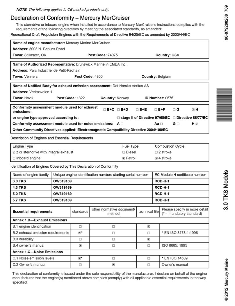
MerCruiser
MerCruiser 3.0 TKS user manual
