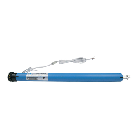
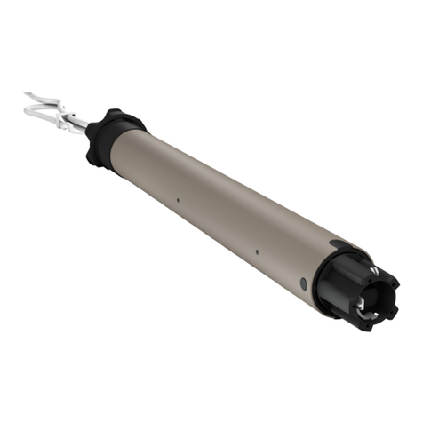
DELTA DORE TYMOOV 6F2 User manual

EN Tubular Motor range
TYMOOV
6F2 - 10F2 - 20F2

EN
2 3
Recommendations
WARNING: Important security instructions
Incorrect installation may cause severe injury
Follow all the instructions and keep this installation guide in a safe
place.
- TYMOOV xF2 motors are designed solely for the operation of
roller shutters for home use. For any other use, please contact our
technical department.
- The minimum inner diameter of the roller tube is 47 mm, but the
tube must be chosen according to the weight and length of the
apron. Consult the tube manufacturers’ charts.
- Do not operate the roller shutter if people or objects are in the
movement area.
- The moving parts of the motor, installed at a height of less than
2.5m, must be protected.
- Before installing the motor, remove all superuous cords and take
out of service any equipment not required for the motor to operate.
- IMPORTANT: Do not operate the shutters or cut off their power
supply when maintenance or cleaning work is being carried out on
the equipment or in close proximity (e.g. window cleaning).
- Monitor the shutter when it is moving and stand clear until it is
completely closed.
-
Do not allow children to play with the xed control devices. Keep
remote control devices out of the reach of children.
- This device may be used by children aged 8 years or older and
by persons with reduced mobility or reduced sensory or mental
capacities, or persons lacking in experience or knowledge, provided
that they are properly supervised or have been given instructions on
how to use the device safely and that the risks involved have been
understood.Children must not play with the device. Cleaning and
maintenance by the user must not be carried out by unsupervised
children.
- The operating device of an unlockable switch must be in direct view
of the driven part, but kept away from the moving parts. It must be
installed at a height of at least 1.5m.
- The xed control devices must be installed in a visible area.
- When using an unlockable switch, ensure that all other
persons in the room stand clear of it;
- Frequently check the equipment to detect any imbalances or signs of
wear or damage to cables and springs.
- Do not use the device when repairs or adjustments are required.
Preliminary elements
- Sufciently rigid roller shutter blades should be used.
- When the roller shutter is closed, the apron must not overlap the
runners by more than one 1/2 blade (max.).
- The apron fastenings or automatic fasteners used on the shutter
must comply with the recommendations for use provided by the
manufacturer
The maximum locked rotor torques for TYMOOV xF2 motors are:
6Nm : 10Nm / 10 Nm: 15Nm / 20 Nm: 27 Nm
Models which cannot support these torques cannot be mounted.
The number of fasteners must be adjusted according to the model
and number of links.
- If used with upper stops, preferably use systems built into the
runners.
- Pay attention to the frame rigidity with stop systems on the shutter
blades.
- TYMOOV xF2 motors check the physical stops every 100
operations, so the motor automatically compensates for any apron
movement.
- Correct operation of the motor is ensured if it is installed and used
according to the following recommendations.
The peripheral elements such as the roller tube, supports, fastenings,

EN
4 5
Recommendations
etc. must be chosen correctly and assembled in compliance with
good practice. Furthermore, the motor operating environment and
power required are elements that must be carefully chosen and
assessed. The characteristics of the driven part must be compatible
with the rated load and operating time.
- A-weighted sound pressure level: LpA ≤ 70 dB(A).
- Cables going through a metal wall must be protected and isolated by
a sleeve.
The TYMOOV xF2 cable can be disassembled.
- If the power cable is damaged, it must be replaced by the
manufacturer, after-sales service or similarly qualied personnel in
order to prevent hazards.
- The motor must be chosen according to the requirements of
the load bearing support. See our charts for selecting the motor
according to the shutter type. A plate on the motor indicates the
nominal torque and operating time.
- TYMOOV xF2 tubular motors are designed to operate
intermittently (4 minutes of continuous operation). They are
electronically protected to prevent overheating. If there is a
thermal shutdown, the motor will operate again after a time period
of approximately 30 minutes. To operate again for 4 minutes, the
performance motor must have returned to room temperature.
DELTADORE hereby declares that the motorised systems covered by these
instructions comply with the essential requirements set out by the Machinery
Directive 2006/42/EC and the European directive RED 2014/53/EU.
The EU declaration for this equipment is available on request
from:
Service “Info techniques”
DELTADORE – 35270 Bonnemain (France)
email: [email protected]
DELTA DORE
35270 - BONNEMAIN - France
Because of changes in standards and equipment, the characteristics given in the text and the illustrations in this
document are not binding unless conrmed by our departments.

EN
6 7
Contents
1/ Motor tting.................................................................................................8
1.1 Crown and wheel assembly .................................................................................8
1.2 Assembly in the tube............................................................................................... 8
1.3 Motor head position................................................................................................ 9
1.4 Attaching the motor to the mount.................................................................... 9
2/ Connection ................................................................................................10
3/ Stop settings..............................................................................................11
3.1 Stop settings............................................................................................................. 11
3.2 Setting 2 automatic stops .................................................................................. 12
3.3 Setting 1 manual stop + 1 automatic stop.................................................. 13
3.4 Setting 2 manual stops ........................................................................................ 14
4/ Clearing stops ..........................................................................................15
4.1 By wiring .................................................................................................................... 15
4.2 By the inverter (2 options) ................................................................................ 15
5/ Troubleshooting.......................................................................................16
• Power supply: 230V - 50 Hz +/- 10%
• Class II insulation
• Operating time: 4 minutes
• Electrical powers:
TYMOOV 6F2 : 40 W
TYMOOV 10F2 : 50 W
TYMOOV 20F2 : 70 W
• Weighted noise pressure level A: LpA ≤ 70 dB(A).
• Degree of protection: IP 44
• Operating temperature: -20°C -> + 60°C
Technical characteristics

EN
8 9
1/ Motor fiing
• Never hit the motor head or output shaft to t the motor into the tube.
Never pierce the tube when the motor is installed.
• To attach the apron, use screws that do not enter the tube
by more than 1 mm.
1.1 Crown and wheel assembly
1.2 Assembly in the tube
For attachment and driving accessories as well as mechanical parts,
consult our catalogue.
Model Length for drilling (L) Total length
TYMOOV 6Nm, 10 Nm and
20 Nm
395 mm 422 mm
Tube
L: length for drilling wheel
attachment by screws or rivet
1.3 Motor head position
The motor head must be positioned on the mount such that the cable outlet is in
the lower part when seen horizontally.
1.4 Aaching the motor to the mount
Push the tube/motor (A) onto the mount (B) until it locks into place (click).
8 NO 8 NO 8 NO
4 OK 4 OK 4 OK
Cable
1
2
Crown
Motor head
Wheel
“Click”
(A)
(B)
“Click”
Ensure that you create a loop in the
power cable to prevent water entering
the motor
It is strictly prohibited to
screw into the motor head.

EN
10 11
2/ Connection 3/ Stop seings
3.1 Stop seings
You can use Auto mode if there are both upper and lower physical stops. The motor
will automatically detect its end of travel distances.
If there are no upper physical stops and/or automatic locks, you must set the end of
travel manually.
You can use the step by step mode to stop the shutter in the exact position you
choose.
There are several ways to congure stops:
• 2 automatic stops,
• 1 manual stop and 1 automatic stop,
• 2 manual stops.
• There is no priority direction for the stop teaching process.
The recording of the rst stop, whether high or low, will be conrmed by a single
movement of the motor, and the second by 2 movements.
• Match the direction of the inverter with the direction of the shutter by
changing the inverter wires (reverse the black wire and the brown wire).
• IMPORTANT: This operation must be done before saving the rst stop.
The electrical wiring must comply with EN, IEC and national institute standards for
installation (e.g.: NF C15-100 for France).
In all cases, it must still be possible to switch off the power supply by using an
omnipolar device in accordance with the applicable installation requirement. If
the motor is delivered with a H05VVF power cable, this cable cannot be placed
outdoors, unless it is inside a UV-resistant duct.
For an outdoor use, the motor must be equipped with a RNF or RRF rubber cable
with at least 2% carbon. Contact the sales department.
Connection a with fixed or temporary
position reversing mechanism
- A change-over switch prohibiting the buttons or from being pressed
simultaneously must be used.
- In the case where a change-over switch with temporary positions is used, the
user must press and hold the button throughout the shutter operating time.
- You can wire up to 3 motors on the same change-over switch for grouped controls,
but motor stops must be adjusted separately.
3 x 0.75 mm2
2 x 1.5 mm2
L
L
N
N
Blue Common (Neutral)
Brown Phase for rotation or .
Black Phase for rotation or .
L Phase
N Neutral
Black Brown
Brown
Blue
Blue
Note: If the raise and lower
directions are reversed, swap the
brown and black wires ( and on
the change-over switch).
230 V, 50 Hz
single-phase
power supply
You can connect Tyxia 5630/5730 nanomodules to Tymoov hard-wired motors
(Tyxia 5630 recommended).
Make sure they are compatible by checking that the manufacturing date code is
greater than or equal to the following one:
Tyxia 5630: 19d10
Tyxia 5730: 19h10
the shutter travel time must also be adjusted after setting the motor stops. To do
this, download the Tyxia 5630/5730 manual and follow the ‘Manual adjustment
for the shutter travel time’ procedure in the ‘Additional information’ section.

EN
12 13
3/ Stop seings
3.2 Seing 2 automatic stops
It is possible that after the learning process the shutter will move in the opposite
direction to the button you press.
If that is the case, you can reverse the direction by pressing the following
sequence of buttons:
- (at <1 second intervals) + (hold >3 seconds),
OR
- (<1 second intervals) + (hold >3 seconds).
The motor will be activated once.
The mode will be automatically exited.
x 2
x 2
The shutter will not be locked when these stops are subsequently reached.
The motor will reverse its direction slightly so that there is no force on the
shutter.
The shutter will not be locked when these stops are subsequently reached.
The motor will reverse its direction slightly so that there is no force on the
shutter.
x 1
Upper physical
stop
Lower physical
stop
Stop on shutter
blade
Press and hold the
button briey until the
shutter reaches the upper
stop.
The stop position will now be automatically set.
The motor will be activated once.
Press and hold the button until the shutter locks against the
lower stop.
The stop position will now be automatically set.
Press and hold the button until the shutter locks against the
lower stop.
The stop position will now be automatically set.
The motor will
be activated
twice
The motor will
be activated
twice
❶ Automatic upper stop
❷ Automatic lower stop
❸ Automatic lower stop
❸ The stops are set
❹ The stops are set
3.3 Seing 1 manual stop + 1 automatic stop
Press and hold the button until the shutter is in the required
position. Upward slow mode (step by step) with the following
sequence of buttons:
OO(at <1 second intervals), then long press on until
the shutter reaches the required position.
Press the following button sequence:
OO(at <1 second intervals), then long press on .
The motor briey starts once.
❶ Manual upper stop
❷ Setting the upper stop
x 2
x 1

EN
14 15
3/ Stop seings
Press and hold the button until the shutter is in the required
position. Upward slow mode (step by step) with the following
sequence of buttons:
OO(at <1 second intervals), then long press on
until the shutter reaches the required position.
Press the following button sequence:
OOO(at <1 second intervals), then long press on
.
The motor briey starts twice.
❶ Manual upper stop
❸ Manual lower stop
❹ Setting the lower stop
3.4 Seing 2 manual stops
x 2
x 1
x 2
x 1
4/ Clearing stops
4.1 By wiring
- Switch off the power supply to the system.
- Connect the black and brown wires to
the raise phase and set the switch to the
‘raise’ position.
- Switch on the system’s power supply
again for less than 10 seconds until the
motor makes 2 movements (forwards/
backwards).
- Switch off the power supply to the
system again.
- Reconnect the black and brown wires as
they were initially (see § Connection).
- Switch on the power supply to the system again.
The stops have now been cleared. You can store them over again.
4.2 By the inverter (2 options)
4.2.1 From the lower position
- Lower the shutter completely,
- Press O(STOP) within 5 seconds following the stop of the shutter,
- Then perform the following sequence:
OO(at <3 second intervals), then long press on .
The motor briey starts twice.
The 2 stops have now been cleared.
OR
4.2.2 From the upper position
- Raise the shutter completely,
- Press O(STOP) within 5 seconds following the stop of the shutter,
- Then perform the following sequence:
OO(at <3 second intervals), then long press on .
The motor briey starts twice.
The 2 stops have now been cleared.
3 x 0.75 mm
2
2 x 1.5 mm2
L
L
N
N
Black Brown Blue
Power supply
230 V, 50 Hz
Single-phase
Press and hold the button until the shutter is in the required
position. Upward slow mode (step by step) with the following
sequence of buttons:
OO(at <1 second intervals), then long press on until
the shutter reaches the required position.
Press the following button sequence:
OO(at <1 second intervals), then long press on .
The motor briey starts once.
❷ Setting the upper stop

EN
16 17
If the motor is not working:
- Check that the wiring corresponds to the diagrams in the “Connection” chapter.
- Check the power supply in the network.
- Check that the motor is not in thermal protection mode; just wait a few minutes
for it to cool down.
- Check whether there is a problem linked to the end of travel settings and
reset them.
The end of travel points are not applied:
- Check the mechanical components of the system
(stabilisation, play, distortion, etc.)
- Check whether there is a fault linked to the end of travel settings and reset them.
Reversal of the direction of rotation when the stops are already set.
- Raise the shutter completely,
- Press O(STOP) within 5 seconds following the stop of the shutter,
- Then perform the following sequence:
OOOO(at <3 second intervals), then long press on .
The motor briey starts twice.
Check the direction of rotation of the motor.
5/ Troubleshooting

www.deltadore.com
12/20
This manual suits for next models
2
Table of contents
Other DELTA DORE Engine manuals
DELTA DORE
DELTA DORE TYMOOV 30FB User manual
DELTA DORE
DELTA DORE TYMOOV 2 Silence+ 10 User manual
DELTA DORE
DELTA DORE TYMOOV radio RP2 Series User manual
DELTA DORE
DELTA DORE TYMOOV 30FB User manual
DELTA DORE
DELTA DORE TYMOOV RP Series User manual
DELTA DORE
DELTA DORE TYMOOV IOFB User manual
DELTA DORE
DELTA DORE TYMOOV F Series User manual
