Circuit Fitness AMZ-167RW Installation and operating instructions

© IMPEX INC.
www.marcypro.com
NOTE:
Please read all instructions
carefully before using this
product
Table of Contents
Water Rower
AMZ-167RW
Safety Notice
Hardware Pack
Assembly Instruction
Parts List
Warranty
Ordering Parts
Model
AMZ-167RW
Retain This
Manual for
Reference
190722
ASSEMBLY &
OWNER'S
MANUAL
IMPEX® INC.
2801 S. Towne Ave, Pomona, CA 91766
Tel: (800) 999-8899 Fax: (626) 961-9966
www.marcypro.com
support@impex-fitness.com

1
© IMPEX INC.
www.marcypro.com
Toll-Free Customer Service Number
1-800-999-8899
Mon. - Fri. 9 a.m. - 5 p.m. PST
www.marcypro.com
TABLE OF CONTENTS
BEFORE YOU BEGIN
1
IMPORANT SAFETY NOTICES
2
WARNING LABEL PLACEMENT
3
PRE-ASSEMBLY CHECK LIST
4
HARDWARE PACK
5
ASSEMBLY INSTRUCTION
6
EXPLODED DIAGRAM
9
PARTS LIST
10
CARE AND MAINTANENCE
12
OPERATING NOTES
12
ADJUSTMENT GUIDE
13
STORAGE GUIDE
15
COMPUTER
16
EXERCISE GUIDELINES
19
WARRANTY
21
ORDERING PARTS
21
BEFORE YOU BEGIN
Thank you for selecting the CIRCUIT FITNESS Water-Resistance Rower AMZ-
167RW by IMPEX® INC. For your safety and benefit, read this manual carefully
before using the bike. As a manufacturer, we are committed to provide you
complete customer satisfaction. If you have any questions, or find there are missing
or damaged parts, we guarantee you complete satisfaction through direct
assistance from our factory. To avoid unnecessary delays, please call our TOLL-
FREE customer service number. Our Customer Service Agents will provide
immediate assistance to you.

2
© IMPEX INC.
www.marcypro.com
IMPORTANT SAFETY NOTICE
PRECAUTIONS
This exercise machine is built for optimum safety. However, certain precautions apply
whenever you operate a piece of exercise equipment. Be sure to read the entire manual
before you assemble or operate your machine. In particular, note the following safety
precautions:
1.
Keep children and pets away from the machine at all times. DO NOT leavechildren
unattended in the same room with the machine.
2.
Only one person at a time should use the machine.
3.
If the user experiences dizziness, nausea, chest pain, or any other abnormalsymptoms,
STOP the workout at once. CONSULT A PHYSICIAN IMMEDIATELY.
4.
Position the machine on a clear, leveled surface. DO NOT use the machine near wateror
outdoors.
5.
Keep hands away from all moving parts.
6.
Always wear appropriate workout clothing when exercising. DO NOT wear robes or other
clothing that could become caught in the machine. Running or aerobic shoes are also
required when using the machine.
7.
Use the machine only for its intended use as described in this manual. DO NOTuse
attachments not recommended by the manufacturer.
8.
Do not place any sharp object around the machine.
9.
Disabled person should not use the machine without a qualified person or physicianin
attendance.
10.
Before using the machine to exercise, always do stretching exercises to properly warm up.
11.
Never operate the machine if the machine is not functioning properly.
12.
Read all warnings posted on the exercise bike.
13.
Inspect the exercise bike for worn or loose component prior to use. Tighten/replace any
loose or wore components prior to use.
14.
Care should be taken in mounting or dismounting the exercise bike.
15.
This exercise bike is for consumer and home use only.
WARNING: BEFORE BEGINNING ANY EXERCISE PROGRAM, CONSULT YOUR
PHYSICIAN. THIS IS ESPECIALLY IMPORTANT FOR INDIVIDUALS OVER THE AGE OF
35 OR PERSONS WITH PRE-EXISTING HEALTH PROBLEMS. READ ALL
INSTRUCTIONS BEFORE USING ANY FITNESS EQUIPMENT. IMPEX INC. ASSUMES NO
RESPONSIBILITY FOR PERSONAL INJURY OR PROPERTY DAMAGE SUSTAINED BY
OR THROUGH THE USE OF THIS PRODUCT.
SAVE THESE INSTRUCTIONS.


6
© IMPEX INC.
www.marcypro.com
35
65 4
58
65
27
58
3
50
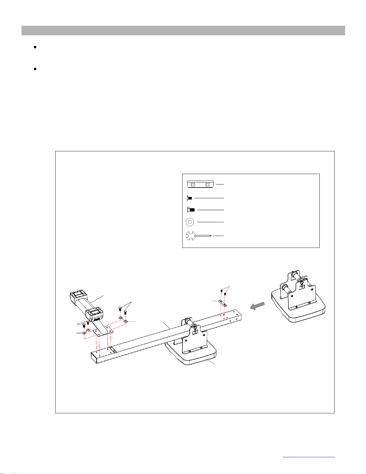
# 27 Limit pad 1pc
# 50 M6*⅜ 2pcs
# 58 M8*⅝ 4pcs
#65 OD20*ID8.5*1.5 4pcs
# 76 S13-17
ASSEMBLY INSTRUCTION
. Tools Required for Assembling the Machine: One Crossing Wrench and Allen Wrench,
provided by manufacturer.
. NOTE: It is strongly recommended that two or more people assemble this machineto
avoid possible injury.
STEP-1
1. Turn over the Slide Rail (#4), the Rear Stabilizer (#3) and the seat (#35) as below picture.
2. Slide the seat (#35) onto the rail (4). Attach Limit Pad (#27) to the Slide Rail (#4) and secure with
two screws (#50).
3. Attach the Rear Stabilizer (#3) to the Slide Rail (#4), tighten with 4 Washers (#65) and 4 Outer
hex Bolt (#58).

8
© IMPEX INC.
www.marcypro.com
#60 M8*⅝ 8pcs
#65 OD20*ID8.5*1.5 8pcs
#74 S5
1
65
65
65
60
2
65
STEP-3
Keep the Main Frame (No.1) upright. Attach Front Stabilizer (No.2) to Main Frame (No.1) using 8
Washers (No.65) and 8 Screws (No.60). Tighten with Allen Wrench (No.74).
Note: You can put 3~4 screws into the holes first, and start tightening by hand. After all the screws
are put in, then tighten with the tool.
60
60
60

9
© IMPEX INC.
www.marcypro.com
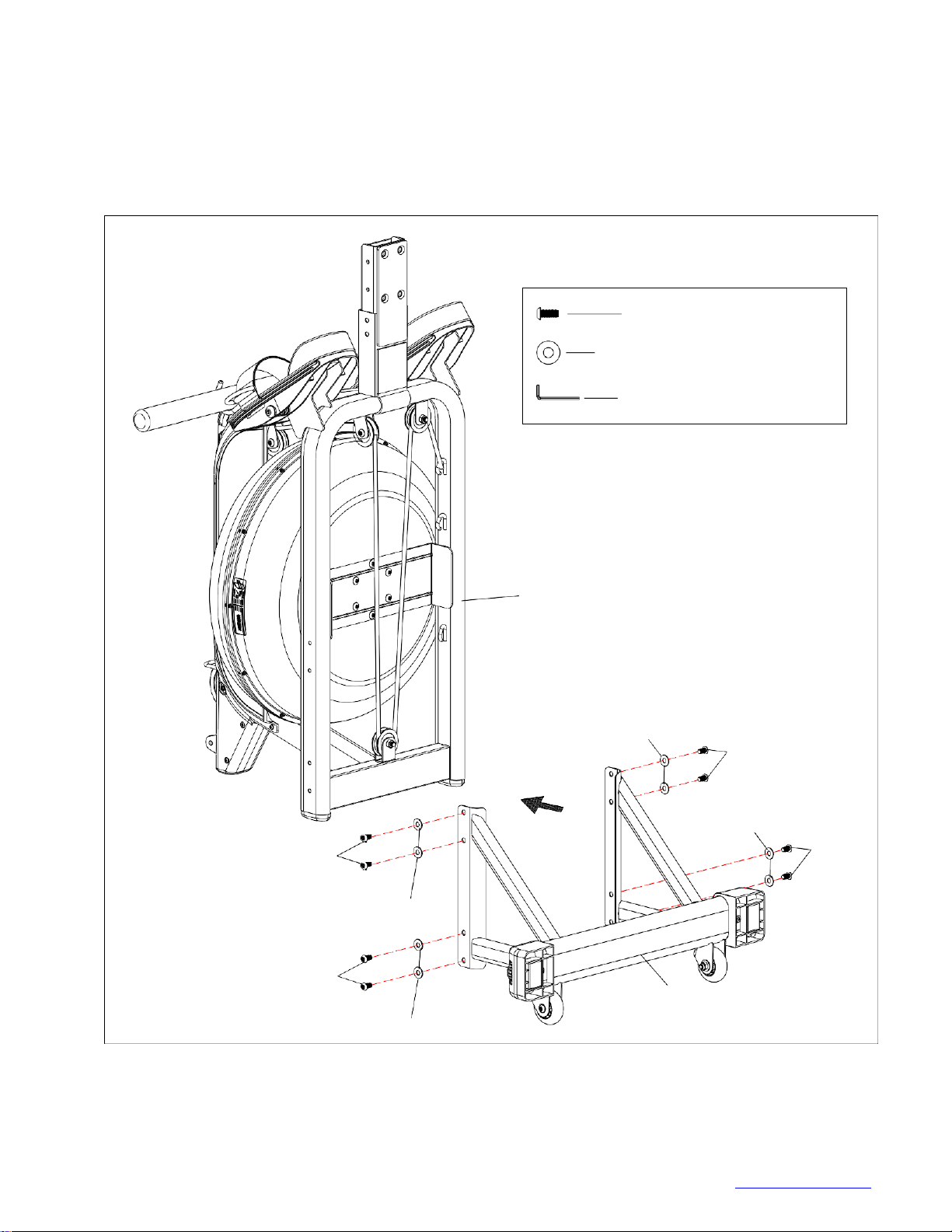
4
35
60
65
60
65
53
53
1
#53 M8*⅝ 4pcs
#60 M8*⅝ 8pcs
#75 OD20*ID8.5*1.5 8pcs
#74 S5
STEP-4
1. Slide the Seat (No.35) onto the Slide Rail (No.3).
2. Attach the Slide Rail (No. 4) to the Main Frame (No. 1) using 4 Flat Screws (No. 53).
with 4 Washers (No.65) and Screws (No.60).Insert all 8 screws partially into the holes first, and then
tighten with Allen Wrench (No.74).

10
© IMPEX INC.
www.marcypro.com
1
54
43
42
65
41
70
#76 S13-17 1pc
#75 S5 1pc
#65 OD20*ID8.5*1.5 1pc
#70 M8 1pc
#54 M8*2½ 1pc
STEP-5
1. Connect the Connection wire (No. 43) to the Sensor wire (No. 42).
2. Attach the Support for computer (No. 41) to Main Frame (No. 1), using 1 Screw (No.54) with
Washer (No.65) and Nylon lock nut (No.70). Tighten with Allen Wrench (No.75) and Spanner
(No.76).
The assembly is complete!

11
© IMPEX INC.
www.marcypro.com
EXPLODED DIAGRAM
42
61 40
50
44
50
11
48
28 68
16
28 47
29 60
60
65
61 65
31 2
61 61
41
56 39
70
57 7065 8
57
43 65 54
9
70 39 56
29 65
23 14
6 69
65 65 61
67
20 46 64
65
60
70 65 61 60
60
60 26 61
10
12
19
1
45 34
37 54
13
21
49
45 34
333470
49
333470 15 37 69
61
67
19
62 25 63
17
49
45 32
34
53 33
34
70
36
45
34
33 61
34
70
61
68 60 65
48 65
24 4 60
27
50
55
5
18
30
29 65
72 63 58
27
51
50
52 66
71
65
58
35
49 49
7
59 7
61 38
74 3 22
73 75 38
29
76 61
65
71
66 59 70
64

12
© IMPEX INC.
www.marcypro.com
AMZ-167RW PARTS LIST
No.
Description
Spec.
QTY
1
Main Frame
1
2
Front Stabilizer
1
3
Rear Stabilizer
1
4
Slide Rail
1
5
Handlebar
1
6
Tank Plate
1
7
Seat Carriage
2
8
Support for Computer
1
9
Support Plate
1
10
Handlebar seat
1
11
Fixing Plate For Belt Wheel
1
12
Impeller
1
13
Belt Wheel
POM,Black
1
14
Guide Roller
POM,Black
1
15
Lower Guide Roller
PU,Black
1
16
Mesh belt wheel
POM,Black
1
17
Upper Tank
PC
1
18
Lower Tank
PC
1
19
Shroud
HIPS,Black
2
20
Front Cover L
PP,Black
1
21
Front Cover R
PP,Black
1
22
Seat Roller
POM,Black
3
23
Magnet Seat
POM, black
1
24
Rubber Sealing Ring
Rubber
1
25
Fill Plug
Rubber,Black
1
26
Impeller Shaft Seal
Rubber, black
1
27
Limit pad
Rubber, black
2
28
Plastic washer
POM, black
2
29
Adjustable end cap
PP, black
4
30
Rail end cap
PP, black
1
31
Left Pedal
PP, black
1
32
Right Pedal
PP, black
1
33
Bungee pulley
POM, black
4
34
Spacer for Bungee pulley
ABS,black
8
35
Seat
PU,Black
1
36
Bungee cord
Nylon, black
1
37
Support Sleeve
4
38
Spacer for Roller
6
39
Moving Wheel
PU,Black
2
40
Sensor holder
Nylon, black
1
41
Computer
1
42
Sensor wire
L450
1
43
Connection Wire
L500
2
44
Pin
1
45
Bolt
M8*1⅛
4
46
Bolt
M10*2¾
2
47
Bolt
M10*2⅛
1

13
© IMPEX INC.
www.marcypro.com
48
Bolt
M12*4⅞
2
49
Bolt
M6*15
18
50
Flat head Crosshead Screw
M6*⅜
6
51
Bolt
M8*4⅞
2
52
Bolt
M8*5⅛
1
53
Flat head Bolt
M8*⅝
4
54
Bolt
M8*2½
2
55
Crosshead Screw
M5*1⅛
1
56
Bolt
M8*1¾
2
57
Crosshead Screw
M5*½
4
58
Outer hex Bolt
M8*⅝
4
59
Adjusting Screw
M6*1⅝
2
60
Bolt
M8*⅝
16
61
Crosshead Screw
M4*⅝
17
62
Crosshead Screw
M3*⅞
12
63
Washer
OD7*ID3.2*1.0
24
64
Washer
OD25*ID10.5*2.0
4
65
Washer
OD20*ID8.5*1.5
26
66
Adjusting Bolt Fixing Plate
2
67
Crosshead Screw
ST4.2*12
2
68
Hexagonal nut
M12
2
69
Nylon lock nut
M10
3
70
Nylon lock nut
M8
11
71
Nylon lock nut
M6
2
72
Nylon lock nut
M3
12
73
Funnel
1
74
Pumping Siphon
1
75
Allen Wrench
S5
1
76
Allen wrench
S13-S17
1
CARE AND MAINTENANCE
1. Inspect and tighten all parts each time you use the machine. Replace any worn parts
immediately.
2. This machine can be cleaned using a damp cloth and mild non-abrasive detergent. Do notuse
solvents.
3. Store the rower IN-DOOR. Excess moisture and water would cause rust on the frame.
4. The rower shall be placed at least 24 inches away from the wall or/and any other object suchas
furniture to provide safe access to and passage around the machine.
5. Toavoid possible injury, the help of two or more people are needed when moving the machine
around.
6. Disposal Instructions –The equipment can be safely disassembled and disposedwithout
unreasonable hazards. Call your local recycle agency regarding details of recycling.
7. The maximum user weight is 300 lbs.
8. Assembled Dimension (L x W x H): 78.75”x22.05”x42.13”
14
© IMPEX INC.
www.marcypro.com
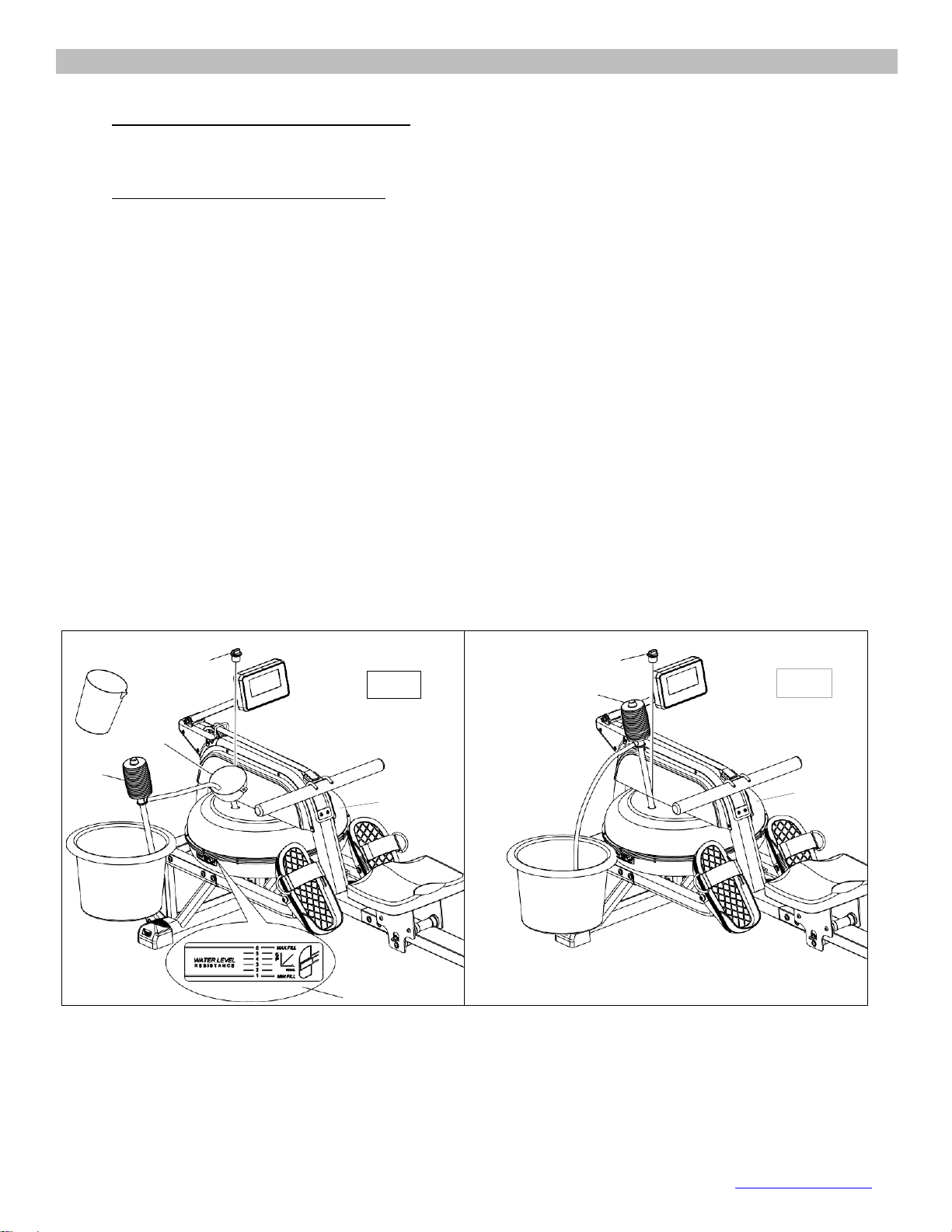
OPERATING NOTES
1.
Remove the Fill Plug (No.25) from the Upper Tank Cover (No.17).
2.
To fill tank with water, refer to Fig. A. Insert the Funnel (No.73) into the tank, then use a cup or
the Siphon Pump (No.74) and a bucket to fill the tank. Use the water level gauge on the side of
the tank to measure desired water level in the tank.
3.
To empty the tank, refer to Fig. B. Place a bucket next to the rower, and use the Siphon Pump
(No.74) to pump out the water from the tank into the bucket.
4.
Insert the Fill Plug (No.25) into the Upper Tank Cover (No.17). Wipe excess water off of the
frame.
NOTE:
•Fill the tank onlywith tap water. Add 1 water-purification tablet (1 packet is included.). Never use
pool chlorine or chlorine bleach. This will damage the tank and void the warranty.
•Add a water purification tablet every 6 months or as needed. If water remains cloudy, replace
the water in the tank.
•Water from the tank is not suitable for consumption. Dispose the water after pumping it out from
the tank.
A.W ATER LEVEL
•See Fig. A. The water level gauge is on the side of the tank. The maximum fill level is 6. Never
fill it over this limit. Filling the tank over this limit will void the warranty.
•The resistance depends on the water level in the tank. Water level 1 is the lowest resistance.
Level 6 is the highest resistance.
74
73
25
Fig.A
17
Water level label
25
74
Fig.B
17
15
© IMPEX INC.
www.marcypro.com
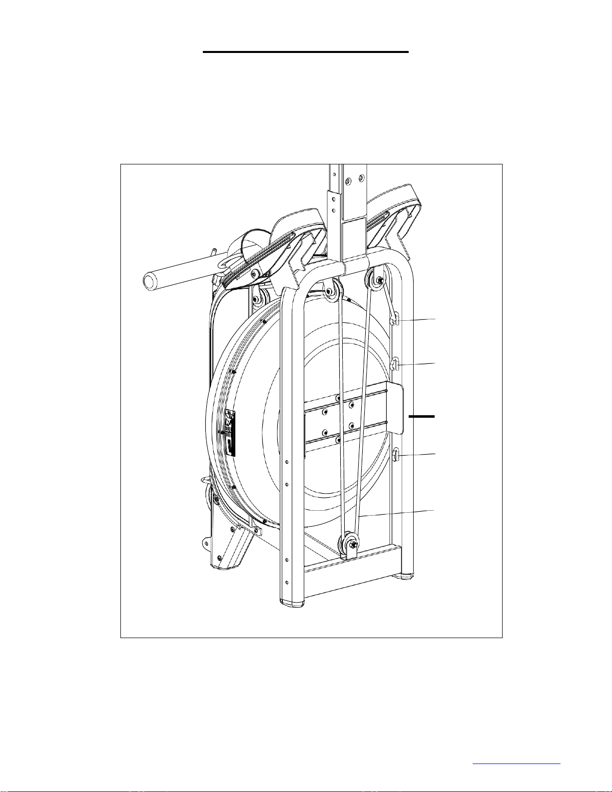
A
B
1
C
36
ADJUSTMENT GUIDE
There are 3 hooks (A, B, C) for the bungee cord (No.36), located on the inside of the frame under the
water tank. If you hook the bungee cord on to B or C, it increases the assisted return of the mesh belt.
C is the fastest return.
Use caution when adjusting the bungee cord.

16
© IMPEX INC.
www.marcypro.com
Adjusting the Pedal
The pedal strap is adjustable and can be
personalized to fit the user’s foot size.
Release Velcro strap by pulling it upward
by the D-Ring, adjust the size to fit.
Tighten the pedal strap around your foot,
by pulling down to secure it.
MOVING THE MACHINE
To move the machine, lift up the rear
stabilizer until the transportation wheels on
the front stand touch the ground. With the
wheels on the ground, you can transport
the rower to the desired location with ease.
To Stabilize the Rower
Adjust the Rear Stabilizer of the machine if
the machine is unbalanced during use.
3
29

17
© IMPEX INC.
www.marcypro.com
3
4
CAUTION!
Move with caution when you
raise the rower up, as your
head may touch the Rear
Stabilizer.
35
35
CAUTION!
When you stand the
rower up, the Seat will
slide down.
4
3
When not in use, you can save space by storing
the rower vertically.
If you plan to not use the rower for more than a
month, empty the tank prior to storing.
STORAGE GUIDE
Caution!
Moving parts, such as the seat, can cause injury. Keep hands clear of the sliding rail during use!

© IMPEX INC.
www.marcypro.com
COMPUTER
Our computerized display console on the Water Rower allows the user to tailor a
personalized workout by monitoring their progress. During a workout, the display
console will alternately and repeatedly display the Time, Time/500M, SPM, Distance,
Strokes, Total Strokes, Calories Burned and Pulse.
BUTTONS
UP▲/ DOWN▼:Press either buttons to cycle through available selections, and to
adjust the function value upward or downward.
ENTER: To confirm your selection.
During training, press the button to scan through each display function.
START / STOP: To start and stop your selected workout program.
RESET: Press to go back to the main menu.
Long press (3-5 seconds) will reset all values back to zero.
RECOVERY: To activate the RECOVERY PROGRAM that will automatically evaluate
your fitness immediately after your work out.
DISPLAY FUNCTIONS
TIME: Set target time by pressing UP or DOWN buttons (1min ~ 99 min), in 1-min.
increments.
TIME/500M: Your average 500-meter time will automatically be displayed and
continuously updated.
SPM: Strokes per minute.
DISTANCE: Set target value by pressing UP or DOWN buttons (0 ~ 99900 meters) in
100-meter increments.
STROKES: Preset target value by pressing UP or DOWN buttons (0~9990 strokes) in
10-stroke increments.
TOTAL STROKES: Accumulates total strokes from 0 up to 9999.
CALORIES: Set target CALORIES by pressing UP or DOWN buttons
(10Cal ~9990Cal) in 10-Cal. increments.
PULSE: In Manual Mode, set target value by pressing up or down button to set from 30
to 240, in 1 BPM increments. The computer will display user’s heart rate during
training. When target value is reached, computer will beep until you change to
another mode or take off Chest belt. Also, the Pulse ICON will blink. The pulse
function will only work if it is connected to a chest strap system (not included).
CALENDAR: The computer will display year, month, and day when computer is in sleep
mode.
TEMPERATURE: The computer will display the current room temperature when the
computer is in sleep mode.
19
© IMPEX INC.
www.marcypro.com
CLOCK: The computer will display current time when the computer is in sleep mode.
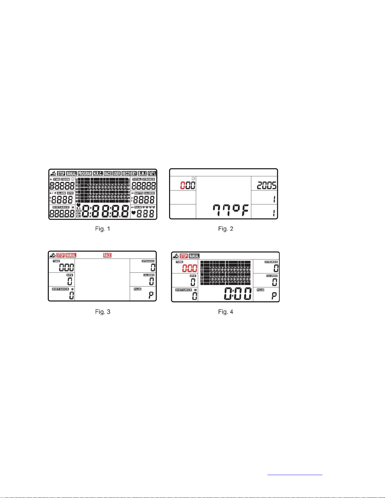
OPERATION
1.
Install 2 AA batteries (included) and computer will beep for 2 seconds(Fig.1).
The computer will enter into the CLOCK & CALENDAR MODE (Fig.2).
2.
The CLOCK will flash. Press UP/DOWN to set the hour. Press ENTER toconfirm.
Press UP/DOWN to set the minutes. Press ENTER to confirm. Continue to set up
YEAR (displays in the STROKES window); MONTH (displays in the CALORIES
window); DAY (displays in the PULSE window) by pressing UP or DOWN. Each
time, press ENTER to confirm.
After setting the CLOCK, the ALARM icon will blink for you to set up an alarm. To
skip setting up an alarm, press ENTER.
To set up an alarm, press UP KEY to turn on ALARM. An arrow will appear next to
ALARM.
Press ENTER. CLOCK window will flash. Press UP or DOWN to set the alarm time.
Press ENTER to confirm. Computer will go into the SPORT screen (Fig.3).
3.
When you enter into the SPORT screen, MANUAL and RACE will blink. Press UP or
DOWN to select MANUAL or RACE. Press ENTER to confirm your selection.
(1)
MANUAL (Fig.4): There are 2 options in MANUAL mode.
A. The computer can be set to countdown.
i. When you select MANUAL, the value of TIME will start to flash. Press
UP/DOWN to set the value of TIME to countdown. Press ENTER to
confirm it. If you do not want to set the value of time to COUNTDOWN,
press ENTER to go to the next function.
ii. You can set the values for DISTANCE, STROKES, CALORIES, or
PULSE. (You can only set the value for one function to countdown. For
example, if you have set the target value for TIME, then DISTANCE can’t
be set.)
iii. Press START button to start. The STOP icon will disappear.
iv. When the function you have selected counts down to zero or you press
STOP button, the computer will stop and display the averagevalue.
Table of contents
Other Circuit Fitness Home Gym manuals

Popular Home Gym manuals by other brands

ParaBody
ParaBody Home Guide user guide

York Fitness
York Fitness Aspire Rower 56019 owner's manual

SportsArt Fitness
SportsArt Fitness P751 owner's manual

Pure Fitness
Pure Fitness 8639FID owner's manual

SKLZ
SKLZ Power Strapz Instruction manual and exercise guide

Weider
Weider Easy Compact 90 Manual do utilizador


