Circutor SGE-3G/GPRS User manual

INSTRUCTION MANUAL
Modem/Router
SGE-3G/GPRS
(M179B01-03-17A)

2
SGE-3G/GPRS
Instruction Manual

3
Instruction Manual
SGE-3G/GPRS
SAFETY PRECAUTIONS
DANGER
Warns of a risk, which could result in personal injury or material damage.
ATTENTION
Indicatesthatspecialattentionshouldbepaidtoaspecicpoint.
Follow the warnings described in this manual with the symbols shown below.
If you must handle the unit for its installation, start-up or maintenance, the following
should be taken into consideration:
Incorrect handling or installation of the unit may result in injury to personnel as well as damage
to the unit. In particular, handling with voltages applied may result in electric shock, which may
cause death or serious injury to personnel. Defective installation or maintenance may also
leadtotheriskofre.
Read the manual carefully prior to connecting the unit. Follow all installation and maintenance
instructions throughout the unit’s working life. Pay special attention to the installation stan-
dards of the National Electrical Code.
Refer to the instruction manual before using the unit
In this manual, if the instructions marked with this symbol are not respected or carried out correctly, it can
result in injury or damage to the unit and /or installations.
CIRCUTOR,SAreservestherighttomodifyfeaturesortheproductmanualwithoutpriornotication.
DISCLAIMER
CIRCUTOR, SAreservestherighttomakemodicationstothedeviceortheunitspecica-
tions set out in this instruction manual without prior notice.
CIRCUTOR, SA on its web site, supplies its customers with the latest versions of the device
specicationsandthemostupdatedmanuals.
www.circutor.com

4
SGE-3G/GPRS
Instruction Manual
CONTENTS
SAFETY PRECAUTIONS ���������������������������������������������������������������������������������������������������������������������������������������3
DISCLAIMER ����������������������������������������������������������������������������������������������������������������������������������������������������������3
CONTENTS�������������������������������������������������������������������������������������������������������������������������������������������������������������4
REVISION LOG�������������������������������������������������������������������������������������������������������������������������������������������������������5
SYMBOLS���������������������������������������������������������������������������������������������������������������������������������������������������������������5
1�- VERIFICATIONS UPON RECEPTION ��������������������������������������������������������������������������������������������������������������6
2�- DESCRIPTION OF THE PRODUCT������������������������������������������������������������������������������������������������������������������6
3�- INSTALLING THE DEVICE �������������������������������������������������������������������������������������������������������������������������������7
3�1�- PRELIMINARY RECOMMENDATIONS ����������������������������������������������������������������������������������������������������7
3�2�- INSTALLATION �����������������������������������������������������������������������������������������������������������������������������������������8
3�2�1�- INSTALLATION ON DIN RAIL ������������������������������������������������������������������������������������������������������������8
3�2�2�- PANEL-MOUNTED INSTALLATION ���������������������������������������������������������������������������������������������������9
3�3�- TERMINALS OF THE DEVICE����������������������������������������������������������������������������������������������������������������10
4�- START-UP ������������������������������������������������������������������������������������������������������������������������������������������������������� 11
5�- OPERATION ���������������������������������������������������������������������������������������������������������������������������������������������������12
5�1�- INDICATOR LEDs �����������������������������������������������������������������������������������������������������������������������������������12
5�2�- COMMUNICATIONS PORTS ������������������������������������������������������������������������������������������������������������������13
6�- CONFIGURATION �������������������������������������������������������������������������������������������������������������������������������������������14
6�1�- MODEM ���������������������������������������������������������������������������������������������������������������������������������������������������15
6�2�- DynDNS���������������������������������������������������������������������������������������������������������������������������������������������������15
6�3�- TIME: NTP SERVER �������������������������������������������������������������������������������������������������������������������������������16
6�4�- ETHERNET PORT�����������������������������������������������������������������������������������������������������������������������������������16
6�5�- PORT FORWARDING �����������������������������������������������������������������������������������������������������������������������������17
6�6�- RS-485 �����������������������������������������������������������������������������������������������������������������������������������������������������18
6�7�- RS-232 �����������������������������������������������������������������������������������������������������������������������������������������������������18
6�8�- DELIVERY OF SMS MESSAGES �����������������������������������������������������������������������������������������������������������19
6�9�- SECURITY �����������������������������������������������������������������������������������������������������������������������������������������������19
6�10�- SAVING THE CONFIGURATION ����������������������������������������������������������������������������������������������������������19
7�- TECHNICAL FEATURES ��������������������������������������������������������������������������������������������������������������������������������20
8�- TECHNICAL SERVICE������������������������������������������������������������������������������������������������������������������������������������22
9�- WARRANTY�����������������������������������������������������������������������������������������������������������������������������������������������������22
10�- CE CERTIFICATE������������������������������������������������������������������������������������������������������������������������������������������23

5
Instruction Manual
SGE-3G/GPRS
REVISION LOG
Table 1: Revision log�
Date Revision Description
06/17 M179B01-03-17A Initial Version
Note: The images of the devices are for illustrative purposes only and might differ from the
original device.
SYMBOLS
Table 2: Symbols�
Symbol Description
In compliance with the corresponding European directive.
The unit complies with the 2002/96/EC European directive. Do not dispose of the unit in
a household waste container at the end of its useful life. Observe the local electronic unit
recycling regulations.
Direct current.
~Alternating current.

6
SGE-3G/GPRS
Instruction Manual
1�- VERIFICATIONS UPON RECEPTION
The following must be checked upon reception of the device:
a)Thedevicehasbeensuppliedaccordingtothespecicationsinyourorder.
b) The device has not been damaged during transport.
c) Perform an external visual inspection of the device before connecting it.
d) Check that it has been supplied with the following:
- An installation guide.
Immediately contact the carrier and/or CIRCUTOR's after-sales service if
you detect any problem in the device upon reception.
2�- DESCRIPTION OF THE PRODUCT
The SGE-3G/GPRS can connect an application to the Internet via IP connections locally or
through networks.
The SGE-3G/GPRS can be connected to UMTS networks (Universal Mobile Telecommunica-
tion System) where this technology is installed. Otherwise, it will connect via GPRS networks
(General Packet Radio Service). The SIM card installed must have the necessary services,
whichmusthavebeenactivatedbyitsserviceprovider.InthecaseoffacilitieswithnoxedIP,
the SGE-3G/GPRS is compatible with the DYNDNS service.
The device features:
- 3 communications ports: Ethernet, RS-232 and RS-485.
- 11 Indicator LEDs.

7
Instruction Manual
SGE-3G/GPRS
3�- INSTALLING THE DEVICE
3.1.- PRELIMINARY RECOMMENDATIONS
The people using and handling the device must follow the safety measures es-
tablished in the country where the device will be used to guarantee its safe oper-
ation, using personal protective equipment if needed.
The SGE-3G/GPRSdevicemustbeinstalledbyauthorisedandqualiedstaff.
Disconnect the device from the mains and disconnect the measuring devices before handling,
changing the connections of or replacing the device. Handling the device while it is connected
is hazardous to the people near it.
The cables must be in perfect working order to prevent accidents or injuries to people and/or
damage to the facilities/installations.
Limittheoperationofthedevicetomeasuringthespeciedcurrentorvoltagevalues.
The manufacturer of the device shall not be held responsible for any damage resulting from the
user or installation company failing to observe the warnings and/or recommendations indicated
in this manual nor for the damage derived from the use of non-original products or accessories
or those from other brands.
Inspect the device before using it. Make sure that there are no cracks and that the housing is
intact.
Do not use the device to take measurements if you detect an anomaly or malfunction.
Check the environment in which the device is installed before taking a measurement. Do not
use the device to take measurements in dangerous, explosive, wet or damp environments.
Disconnect the device from the mains and from the power supply (both the de-
vice and its measuring system) before performing any maintenance operations,
repairs or handling any of the connections of the device.
Contact the after-sales service if you detect that the device is not working prop-
erly.

8
SGE-3G/GPRS
Instruction Manual
3.2.- INSTALLATION
While the device is connected, the terminals, opening the cover or removing el-
ements can expose parts that are hazardous to the touch. The device must not
be used until the installation process is complete.
The device must be connected to a power circuit that is protected with GL (IEC 269) or M-type
fuses, rated 0.5 to 2A. It must feature a thermal-magnetic circuit breaker or equivalent device
to disconnect the device from the mains.
The power circuit of the device will be connected with a cable with a minimum cross-section of
1.5 mm².
The device can be connected to other CIRCUTOR modules. To do so, insert the plastic clips,
as shown in Figure 1,toguaranteethatthemodulesarermlyconnected.
Figure 1: Inserting the clips�
The device can be installed on a DIN Rail or mounted on a panel.
3�2�1�- INSTALLATION ON DIN RAIL
Figure 2 shows how the DIN Rail fastening elements must be attached to the rear of the device.
Figure 2:Fitting the DIN Rail xing elements.

9
Instruction Manual
SGE-3G/GPRS
LifttheguidesafterttingtheguidesandmountingtheSGE-3G/GPRS on a DIN rail, to ensure
theyarermlysecured.
3�2�2�- PANEL-MOUNTED INSTALLATION
Figure 3 and Figure 4showdifferentoptionsthatcanbeusedtotthepanelmountingguides.
The modules are somewhat symmetrical, so they can be attached to the panel in different ways.
Figure 3: Option 1: Fitting the panel xing elements.
Figure 4: Option 2: Fitting the panel xing elements.
Figure 5showshowtoinsertthescrewstosecurethepanelxingelements.

10
SGE-3G/GPRS
Instruction Manual
Figure 5:How to insert the screws into the panel xing elements.
3.3.- TERMINALS OF THE DEVICE
Table 3:List of terminals of the SGE-3G/GPRS�
Terminals of the SGE-3G/GPRS
1: Ethernet Communications 5: A, RS-485 Communications
2: RS-232 Communications 6: N, Auxiliary power supply
3: B, RS-485 Communications 7: L, Auxiliary power supply
4: S, RS-485 Communications
1
2
3
4
5
6
7
Figure 6:SGE-3G/GPRS Terminals�

11
Instruction Manual
SGE-3G/GPRS
4�- START-UP
The following conditions must be met to guarantee the proper operation of the SGE-3G/GPRS:
The antenna must meet the GMS frequency range requirements established in each
country.
The SIM card must be supplied by the mobile phone operator and have the data transmis-
sion function active to guarantee its correct operation. The PIN code must be deactivated
before the SIM card is inserted.
The SGE-3G/GPRSModem/Routermustbeconguredonitswebsite,sonoadditionalsoft-
ware is required to start-up the device.
AcomputerwithanEthernetportandanEthernetcrossovercablearerequiredtocongurethe
device. The default IP address of the device is:
IP: 192.168.1.1
Netmask: 255.255.255.0
A secure web protocol (HTTPS) is required to access the SGE-3G/GPRS through the web site.
The device will be accessed from the following address: https://192�168�1�1
The SIM card is inserted through the rear of the SGE-3G/GPRS. Press the button on the slot
to extract the card holder.
Figure 7: Slot used to insert the SIM card�

12
SGE-3G/GPRS
Instruction Manual
5�- OPERATION
5.1.- INDICATOR LEDs
The device features 11 Indicator LEDs, Figure 10 and Table 4.
H
M
L
3G
Stat
PMon
Tx
Rx
Tx
Rx
ON
Figure 8:SGE-3G/GPRS Indicator LEDs�
Table 4: Description of the LEDs
LED Description
HVery good coverage
MGood coverage
LPoor coverage
3G Steady: Device connected to a 3G network
Flashing: Device connected to a GPRS network
Stat Modem active
PMon Concentrator power supply
Tx Delivery of data via RS-232 or RS-485
Rx Reception of data via RS-232 or RS-485
ON The device is working correctly

13
Instruction Manual
SGE-3G/GPRS
5.2.- COMMUNICATIONS PORTS
The SGE-3G/GPRS features three communications ports:
Ethernet (terminal in Table 3) allows the device to communicate with a PC or any de-
vicewithacommunicationport.Thisistheportthroughwhichthedeviceiscongured,
see “6.- CONFIGURATION”�
RS-232 (terminal 2 in Table 3) allows the device to communicate with any device using
thisprotocol.TheportmustbeconguredfromthewebsiteoftheSGE-3G/GPRS�
Table 5: RS-232 Connector�
RS-232 Connector PIN Description
1 GND
2 RX
3 TX
4 CTS
5RTS
6 GND
If the RS-232 port has been deactivated, bridge pins 4 and 5 for at least 3 seconds to
sendSMSmessagestothetelephonenumberconguredinthewebsiteoftheSGE-3G/
GPRS.
RS-485 (terminals 3, 4 and 5 in Table 3) allows the device to communicate with any
otherdeviceusingthisprotocol.Theportmustbeconguredfromthewebsiteofthe
SGE-3G/GPRS�

14
SGE-3G/GPRS
Instruction Manual
6�- CONFIGURATION
After connecting to the LocalArea Network (LAN) and conguring the IP address or DHCP
name, the device features an internal web site where the network protocol and serial port con-
gurationparameterscanbecongured.
To access this web site, simply use a conventional browser and enter the default IP address in
the SGE-3G/GPRS:
https://192�168�1�1
This is a secure web site; select the “Continue to this website (not recommended) option.
Press the "Setup" button to access the setup screen of the SGE-3G/GPRS.
Figure 9showsthehomecongurationscreen.
Figure 9: Home conguration screen.
It shows:
Connection: Type of connection established and power of the signal.
IP address: IP address
Hostname: Name of the DynDNS (only active if the DynDNS has been programmed)
Time: Time of the SGE-3G/GPRS.
Press the Setup button to access the setup screen of the SGE-3G/GPRS.

15
Instruction Manual
SGE-3G/GPRS
6.1.- MODEM
The SGE-3G/GPRS can be connected to 3G or GPRS networks. The parameters provided by
theoperatoroftheSIMcardmustbeconguredtoaccesssomeofthesenetworks.
Figure 10: Setup screen: Modem�
6.2.- DynDNS
The DynDNS service (Dynamic Domain Server) allows the real-time update of information
about domain names in a name server.
The most common use is the assignment of an Internet domain name to a computer with a
variable IP address (in our case, SGE-3G/GPRS with a dynamic IP address). This allows the
establishment of a connection with the device without the need for an Internet connection with
identicationviaaxedIPaddress.
Ethernet connection
Private IP
Sending the IP (publishes) +
Hostname DYNDNS
Servers
DYNDNS
DYNDNS hostname
IP request
Facilitates IP
Computer to which the
SGE-3G/GPRS wants to
connect
DYNDNS
connection
Figure 11: Operation of the DynDNS service�
Users that wish to use the DynDNS service must be registered in the service. To do so, open
the following web site: www�dyndns�org
Figure 12: Setup screen: DynDNS�

16
SGE-3G/GPRS
Instruction Manual
Setup parameters:
Hostname: hostname of the DynDNS service that the user must have created previ-
ously.
User: Name of the user of the DynDNS account to access the service.
Password: Password of the user of the DynDNS account to access the service.
6.3.- TIME: NTP SERVER
The SGE-3G/GPRS can be synchronised with the NTP (Network Time Protocol) time and date
server in a UTC time system.
The default device shows no values, indicating that the system is synchronised with DHCP, pro-
videdthatthenetworkserverallowsthis.2NTPserverscanbecongured,incaseonestops
operating.
Figure 13: Setup screen: Time, NTP server�
The device time can be updated with 2 methods:
1�- Press the Sync to PC Time button to synchronise the time of the SGE-3G/GPRS
with that of the PC.
2�- UsinganNTPtimeserver,forwhichthefollowingsectionsmustbecongured:Pri-
mary NTP server and Secondary NTP server.
6.4.- ETHERNET PORT
The Ethernet port has the following setup parameters:
Hostname: Name of the Ethernet port.
Address: IP Address of the SGE-3G/GPRS
Netmask: Netmask of the device
DHCP: Activates the DHCP server of the SGE-3G/GPRS
First address: Start IP of the DHCP.
Last address: Final IP of the DHCP.
Forced DNS server:DNSusedtoassignthecongurationoftheDHCP.

17
Instruction Manual
SGE-3G/GPRS
6.5.- PORT FORWARDING
Port Forwarding assigns ports to deliver information through a network of different IP address-
es.
Figure 14:Port forwarding example.
Figure 15: Setup screen: Port forwarding�
Setup parameters:
3G Port: Input port of the SGE-3G/GPRS�
Forward to Address: Destination IP Address.
Port: Port of the destination IP Address.

18
SGE-3G/GPRS
Instruction Manual
6.6.- RS-485
The device features an RS-485 communication bus that is used to communicate with external
peripherals, acting as a communications master.
Figure 16: Setup screen: RS-485�
Setup parameters:
Protocol: Communications protocol: TCP or UDP.
Port: Destination port of the device with which the system will communicate.
Packing timeout: maximum waiting time.
Baud rate: Transmission speed: 4800... 115200 bauds.
Data bits: No. of data bits: 7 or 8.
Parity: Parity: None, Even or Odd.
Stop bits: No. of stop bits: 1 or 2.
6.7.- RS-232
The device features an RS-232 communication bus that is used to communicate with external
peripherals, acting as a communications master.
Figure 17: Setup screen: RS-232�
Setup parameters:
Protocol: Communications protocol: TCP or UDP.
Port: Destination port of the device with which the system will communicate.
Packing timeout: maximum waiting time.
Baud rate: Transmission speed: 4800... 115200 bauds.
Data bits: No. of data bits: 7 or 8.
Parity: Parity: None, Even or Odd.
Stop bits: No. of stop bits: 1 or 2.

19
Instruction Manual
SGE-3G/GPRS
6.8.- DELIVERY OF SMS MESSAGES
The device can send SMS messages via port RS-232, see “5.2.- COMMUNICATIONS PORTS”.
Figure 18: Setup screen: Delivery of SMS messages�
Setup parameters:
Number 1 ��� 4: No. of telephones to which the message will be sent.
Message text: text of the message that will be sent.
6.9.- SECURITY
The edit password can be enabled in the SGE-3G/GPRS,avoidingthemodicationofthesetup
parameters. It is not active by default. In case it is activated, the "user" will always be “admin”,
onlythepasswordcanbemodied.
Figure 19: Setup screen: Security�
6.10.- SAVING THE CONFIGURATION
Iftheinformationinanyoftheabovesectionsismodied,itmustbesavedbypressingthe
Save Setup button.
To return to the default setup, press Load default setup
Figure 20: Setup screen: Save the conguration.

20
SGE-3G/GPRS
Instruction Manual
7�- TECHNICAL FEATURES
Power supply
Rated voltage 85 ... 264 V ~
Frequency 50 ... 60 Hz
Power 7 ... 12 VA
Installation category CAT III 300V
Battery
Type CR2032 SLF (ref: 6032 201 501, VARTA)
Working Life 5 years
Clock
Type RTC, powered with battery
Radio Communications
Connection Four-band GSM/GPRS/EDGE: GSM850/900/1800/1900
Double-band HSPA:900/2100
Transmission
GPRS: D/L up to 85.6Kbps, U/L up to 85.6Kbps
EDGE: D/L up to 236.8Kbps, U/L up to 236.8Kbps
UMTS: D/L up to 384Kbps, U/L up to 384Kbps
HSPA: D/L up to 7.2Mbps, U/L up to 5.76Mbps
Antenna: Nominal impedance 50Ω
Antenna: Connector SMA
RS-232 - RS-485 Communications
Fieldbus RS-485 RS-232
Communications protocol UDP - TCP UDP - TCP
Speed 4800 ... 115200 bauds 4800 ... 115200 bauds
Stop bits 1 - 2 1 - 2
Parity None - Even - Odd None - Even - Odd
Ethernet Communications
10/100 Base-T ; Ethernet IEEE802; 10/100 Mbits/s, self-adapting
User interface
LED 11 LEDs
Environmental features
Operating temperature -10ºC ... +50ºC
Relative humidity (without condensation) 5 ... 95%
Maximum altitude 2000 m
Protection degree IP41
Insulation Class II
Mechanical features
Dimensions Figure 21
Other manuals for SGE-3G/GPRS
1
Table of contents
Other Circutor Network Router manuals
Popular Network Router manuals by other brands

TRENDnet
TRENDnet TW100-BRF214 Specifications
Patton electronics
Patton electronics DIAMONDLINK 3201 quick start guide
D-Link
D-Link Ethernet Broadband Router DIR-100 Quick installation guide
Belkin
Belkin F1PI242EGAU Self help guide
NETGEAR
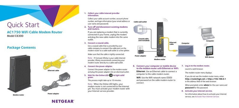
NETGEAR C6300 Quick start quide

Hama
Hama 53120 Operating instruction
