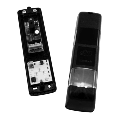
Circutor airBRIDGE RS485 User manual

Router Bridge RS485 to radio
airBRIDGE
INSTRUCTIONS MANUAL
M98250501-03-13A

airBRIDGE
- 2 - of 11 Instructions Manual

airBRIDGE
Instructions Manual 3 of 11
Safety Warnings & Symbols
DANGER
Death, serious injury, or fire hazard could result from improper connection of this equipment. Read and
understand this manual before connecting the equipment. Follow all installation and operating instructions
while using the instrument.
Installation, operation, and maintenance of this instrument must be performed by qualified personnel only.
The National Electrical Code defines a qualified person as “one who has the skills and knowledge related
to the construction and operation of the electrical equipment and installations, and who has received
safety training on the hazards involved.”
Use always the required personal protective equipment
WARNING
Read the instructions manual before using the equipment.
If the instructions preceded by this symbol are not met or applied correctly, this can cause personal injury
or equipment and / or facilities damage.
Liability limitations
CIRCUTOR, SA reserves the right to make changes, without previous notice, to devices or specifications of equipment
shown in this manual.
The term of the CIRCUTOR guarantee is two years from the date of purchase and is limited to refund of the purchase price,
repair free of charge, or replacement of defective equipment that is returned to CIRCUTOR post-sales service within the
term of the guarantee.
The latest versions of specifications and the most up to date manuals of this equipment are available to CIRCUTOR, SA
customers on its web site: www.circutor.com.
Recommendations prior to use
In order to use the equipment safely, it is critical that individuals who handle it, follow the safety
measures set out in the standards of the country where it is being used, use the necessary personal
protection equipment, and pay attention to the various warnings set forth in this instruction manual.
Before handling, modifying the connection or replacing the equipment, the power supply must be switched off, and the
equipment disconnected.
It is important to use only the connection cables and accessories that are delivered along with the equipment . These
products are specially designed for use with this apparatus and comply with current safety standards. Also, it is critical to
keep the cables in perfect condition in order to avoid accidents, personal injury and damage to installations.
The manufacturer of the equipment is not responsible for any damages resulting from failure by the user or installer to heed
the warnings and/or recommendations set out in this manual, nor for damages resulting from the use of non-original
products or accessories or those made by other manufactures.
We recommend using only the original material delivered with the equipment in order to ensure the safety of individuals who
handle it and the integrity of the equipment itself.
Inspect the work area before install. Do not use the device in dangerous areas or where there is a risk of explosion. Avoid
using the device in wet areas

airBRIDGE
4 of 11 Instructions Manual
TABLE OF CONTENTS
Safety Warnings & Symbols ............................................................................................................................................ 3
Liability limitations .......................................................................................................................................................... 3
Recommendations prior to use ....................................................................................................................................... 3
1GENERAL OVERVIEW ............................................................................................................................................... 5
1.1 INITIAL TESTING...................................................................................................................................................... 5
1.2 STANDARD COMPONENTS AND ACCESORIES......................................................................................................... 5
2GENERAL CHARACTERISTICS .................................................................................................................................... 5
3TECHNICAL FEATURES ............................................................................................................................................. 5
4DIMENSIONS ........................................................................................................................................................... 6
5CARD LAYOUT AND CONNECTION DIAGRAM .......................................................................................................... 7
6ASSOCIATE THE DEVICE TO A COMPATIBLE NETWORK ............................................................................................ 7
7DISASSOCIATING THE DEVICE FROM THE NETWORK ............................................................................................... 8
8LED / PUSH BUTTON INTERFACE.............................................................................................................................. 8
9FEAURES OF MODBUS DEVICES CONNECTED TO THE ROUTER-BRIDGE ................................................................... 8
10 CHARACTERISTICS OF THE RADIO TRAFFIC CAUSED BY ROUTER-BRIDGE................................................................. 9
10.1 PROPRIETARY DEVICES.................................................................................................................................................. 9
10.2 GENERIC MODBUS DEVICES (ATTACHED TO A ROUTER-BRIDGE).......................................................................................... 10
11 TRAFFIC LIMITATIONS ........................................................................................................................................... 10
12 ROUTER-BRIDGE DATA .......................................................................................................................................... 10
12.1 ROUTER-BRIDGE INPUT REGISTERS ...................................................................................................................... 10
13 IN CASE OF MALFUNCTION.................................................................................................................................... 11

airBRIDGE
Instructions Manual 5 of 11
1 GENERAL OVERVIEW
1.1 INITIAL TESTING
Upon receiving the equipment, test the following points:
•The equipment meets the specifications of your order
•It has not been damaged during shipping.
•The shipment includes the accessories requested from the manufacturer.
1.2 STANDARD COMPONENTS AND ACCESORIES
With the airBRIDGE you must have received a compatible antenna.
2 GENERAL CHARACTERISTICS
The "airBridge" is a Router Bridge from RS485 to radio. The purpose of this equipment is to permit
communication with standard Modbus devices using ZB-Connection network infrastructure.
The device requires an AC or a DC power supply in order to keep communication.
For network purposes, it has the active function of maintaining radio traffic from and to other similar
devices and it can also act as a parent device for battery-powered sensors of the same family.
See also the manual on ZigBee network Configuration (M98253901-40-13A)
3 TECHNICAL FEATURES
IN (1) Supply
Rated voltage
100 to 240 VCA
Frequency 50 /60 Hz (± 5%)
Consumption
3 VA
Installation Category
300V CATIII
IN (2) DC Internal supply Do not connect simultaneously with IN(1) supply
Rated voltage
12 to 24 Vac
12 to 24 Vcc
Frequency
50 /60 Hz (± 5%)
-
Consumption
2,4 VA
100 mA
COMMUNICATIONS
Interface between
RS-485 to Radio ; IEEE 802.15.4
compliant
RF range
2405 MHz ÷ 2480 MHz
Modulation
DSSS
RF transmission power
0 dBm (1mW)
Protocol
Modbus RTU
Default configuration
9600 baud / No parity / 1 Stop bit
USER INTERFACE
LED indicators
See paragraph 7
ENVIRONMENTFEATURES
Working temperature
-5 … 45 ºC
Storage temperature
-10 … 60 ºC
Relative humidity (without condensation)
95 %
Maximum altitude (m)
2.000
Pollution resistance
II
Degree of protection IP44

airBRIDGE
6 of 11 Instructions Manual
MECHANICAL FEATURES
Weight 332 g
Materials Polycarbonate
Dimensions (mm) 259 x 139,5 x 51,5
Connectors 3,81 mm pitch (pull-out terminals)
STANDARDS
General Legislation 2006/95 EEC (LV Directive)
99/5 EEC (R&TTE Directive)
2004/108 EEC (EMC Directive)
Electrical and radiation safety EN 60950-1 (2006) +A11 (2009)
EN 62479 – (2010)
Electromagnetic Compatibility EN 61000-6-2 (2005)
EN 61000-6-3 (2007)
Electromagnetic compatibility
and Radio spectrum Matters (ERM)
ETSI EN 301 489-1 v1.8.1
ETSI EN 300 328 v1.7.1
ETSI EN 301 489-17 v1.2.1
Communications IEEE 802.15.4
ZigBee , MiWi compatible
4 DIMENSIONS

airBRIDGE
Instructions Manual 7 of 11
5 CARD LAYOUT AND CONNECTION DIAGRAM
Equipment must be connected to external supply through a suitable overcurrent
protective device
6 ASSOCIATE THE DEVICE TO A COMPATIBLE NETWORK
The process to associate a Router-Bridge to a RF network is the usual in all ZB-bridge routers.
The association process is activated automatically by the device in case that the node does not have
any network parameters assigned. This happens if the device is new in the network or if it has been
voluntarily disassociated.
The association process consists of an automatic scanning of all the 16 radio channels, in search of
an “open” and compatible network (ZB-Connection network). Scanning continues about 20 seconds.
At the end of the scanning process if the association process finishes unsuccessfully the device
resets and re-starts a new association process.
Network opening is performed by stimulating the Gateway (for further information, refer to the
document relating to the Gateway).

airBRIDGE
8 of 11 Instructions Manual
7 DISASSOCIATING THE DEVICE FROM THE NETWORK
Device disassociation causes the loss of network parameters, with the consequent exiting of the
device from the network it belongs to. Disassociation can be done in two ways:
-Receipt of the appropriate command password.
-Holding the push button on the PCB for at least 6 seconds. Disassociation using the push-
button is only possible 20 seconds after the device has been switched on.
8 LED / PUSH BUTTON INTERFACE
The Router-bridge has three LED indicator, giving information on the device status. Furthermore, the
Router-bridge has a push-button which allows the sending commands to the device.
Identification of Router-bridge LED indicators (inside the box)
Behaviour of LED indicators at the start-up:
At the reset of Router-bridge all LED indicators light for 2 seconds, then all flash fast for another 2
seconds and after the flashing the device starts the normal operation.
How do the LED indicators work when the router-bridge is NOT ASSOCIATED to a network:
If the router-bridge is not associated to a network, LED “A” is steady ON and LED “B” and “C” are
both OFF
How do the LED indicators work when the Router-bridge is ASSOCIATED TO A NETWORK:
LED “A”: Working Status
Slow flashing (1Hz) -> Router LINKED
Fast flashing (4Hz) -> Router NOT LINKED
LED “B” (middle led): Radio Link
Turned off -> No Router with good link in the proximity
1 flash + pause -> One Router with good link in the proximity
2 flashes + pause-> Two Routers with good link in the proximity
3 flashes + pause-> Four or more Routers with good link in the proximity
LED “C”: Radio Activity
Usually turned off
Short Flash on transmitting or receiving a radio message
9 FEAURES OF MODBUS DEVICES CONNECTED TO THE ROUTER-BRIDGE
Router-Bridge can connect to the ZB-Connection Gateway one or more Modbus devices.
The attached devices must use Modbus -RTU standard.
The Modbus devices are interfaced with the Router-Bridge through the RS485 port (see connection
diagram and default communications parameters). The logic link does not use any hardware
handshaking.
”A” (external led)
”B” (middle led)
”C” (internal led)
Push button

airBRIDGE
Instructions Manual 9 of 11
The communication parameters can be set by means of the 4 DIP-SWITCH on the Router-Bridge
PCB, according to the following table:
DIP1
(baud rate) DIP2 DIP3 DIP4
(stop bit) Baud rate Parity Stop Bit
OFF
OFF
OFF
OFF
9600
None
2
ON
OFF
OFF
OFF
19200
None
2
OFF
ON
OFF
OFF
9600
Even
2
ON
ON
OFF
OFF
19200
Even
2
OFF
OFF
ON
OFF
9600
None
2
ON
OFF
ON
OFF
19200
None
2
OFF
ON
ON
OFF
9600
Odd
2
ON
ON
ON
OFF
19200
Odd
2
OFF
OFF
OFF
ON
9600
None
1
ON
OFF
OFF
ON
19200
None
1
OFF
ON
OFF
ON
9600
Even
1
ON
ON
OFF
ON
19200
Even
1
OFF
OFF
ON
ON
9600
None
1
ON
OFF
ON
ON
19200
None
1
OFF
ON
ON
ON
9600
Odd
1
ON
ON
ON
ON
19200
Odd
1
All the devices connected to the RS-485 bus of a Router-Bridge must have a univocal
address.
All the devices in the same MODBUSPRO network must have an univocal address.
One single duplicated address makes impossible the correct working of the whole
network.
10 CHARACTERISTICS OF THE RADIO TRAFFIC CAUSED BY ROUTER-BRIDGE
A ZB network is composed by several devices which can be divided into two groups:
1. Proprietary devices
2. Generic Modbus devices (attached to a Router-Bridge)
10.1 Proprietary devices
The proprietary devices emit, periodically or after certain events, a frame giving the information on
their internal status, which is detected by the Gateway Master or Coordinator. The data are collected
by the Gateway and stored in the internal memory, to be at disposal when required by the Supervisor
(Agent management).
Coordinator
(Gateway)
Bridge
Repeater
Repeater
End-Device
End-Device
End-Device
End-Device
End-Device
E
E
E
E
E
G
R
R
B
Outside
Supervisor PC or
PLC
N
N
Generic serial
devices
Radio link
Serial link

airBRIDGE
10 of 11 Instructions Manual
If the external device (Supervisor PC or PLC) requires data from a proprietary device, the answer is
obtained from the data locally available in the Gateway. For this reason a data request to a
proprietary device doesn’t generate any radio message, so there is a complete separation between
the local serial communications (between the Gateway and client) and the radio network traffic
(between Gateway and all proprietary devices).
10.2 Generic Modbus devices (attached to a Router-Bridge)
If the external device (Supervisor PC or PLC) requires data from a generic Modbus device the serial
message is converted in a radio message and it is sent to the Router-Bridge to which the generic
Modbus device is attached to.
As the Router-Bridge receives the radio message from the Gateway it arranges to send it through the
serial line.
The answer coming from the generic Modbus device arrives to the Router-Bridge, it is transformed to
a radio message and it is sent to the Gateway which, at last, arranges to turn it into a serial message
to be sent to the outside device.
Gateway and Router-Bridge are substantially responsible only for the transport of the message.
Unlike the first case there is not any separation between the local serial traffic (between Gateway and
outside client) and the radio traffic present in the network.
This involves that for a correct working of the network the local serial traffic must consider the intrinsic
limits of the radio network.
11 TRAFFIC LIMITATIONS
The requests turned to generic Modbus devices have the following limitations:
Message length
Both the requests and the answers must not exceed the length of 52 bytes; this involves the
prohibition to read more than 26 registers (InternalRegister or InputRegister) in a single message.
Request frequency
The time delay between the reception of an answer and the following request must not be less than
one second.
Frequency of the requests in the case of absence for answer
The time gap between two consecutive requests, the first of which has not received an answer, must
not be less than 3 second.
This is translated in a time-out of communication of at least 3 seconds.
12 ROUTER-BRIDGE DATA
It is possible to extract some information about the Router-Bridge’s operation or ID.
This information is accessible through the reading of 12 InputRegister addresses (40001 to 40011).
The reading request should be addressed to the same logical address of one of the Modbus devices
connected to the Router-Bridge.
12.1 ROUTER-BRIDGE INPUT REGISTERS
Input Register[40001]
Router-Bridge Device Type (101)
Input Register[40002]
Router-Bridge Firmware Version
Input Register[40003]
Router-Bridge EUI64 (bytes 0,1)
Input Register[40004]
Router-Bridge EUI64 (bytes 2,3)
Input Register[40005]
Router-Bridge ShortID
Input Register[40006]
Cost (distance from the Gateway in terms of hop)
Input Register[40007]
Wireless Signal Level of the last message received (dB+100)
Input Register[40008]
Number of Router-Bridge neighbours
Input Register[40009]
Number of good Router-Bridge neighbours
Input Register[40010]
Number of End-Device children of Router-Bridge
Input Register[40011]
Received message counter

airBRIDGE
Instructions Manual 11 of 11
13 IN CASE OF MALFUNCTION
In the event of questions or concerns regarding operation or malfunction of the analyzer, notify
Technical Assistance Service (S.A.T.) of CIRCUTOR, SA.
SPAIN 902 449 459
INTERNATIONAL (+34) 93 745 29 00
Technical assistance Post-sales Department
Vial Sant Jordi, s/n –
08232 – Viladecavalls
Barcelona – Spain
e-mail: sat@circutor.es
Web: www.circutor.es
Other manuals for airBRIDGE RS485
1
This manual suits for next models
1
Table of contents
Other Circutor Network Router manuals
Popular Network Router manuals by other brands
Fortinet
Fortinet FortiAP-C24JE quick start guide
D-Link
D-Link DMC-300SC - Media Converter - External Quick installation guide

Siemens
Siemens SIMATIC NET RUGGEDCOM APE1808 Configuration manual

TP-Link
TP-Link Deco BE65 user guide
NetComm Wireless
NetComm Wireless NB16DG Administration manual
ZyXEL Communications
ZyXEL Communications P-2802HW(L)-IX quick start guide

