CIS DCC-HD1 Quick start guide

DCC-HD1 Rev.900-785-30-00
©2013 CIS Corporation. All rights reserved.
FULL HD
Color MOS
Assembly Unit
DCC-HD1
Product Specification
& Operational Manual
CIS Corporation
En
g
lish

DCC-HD1 Rev.900-785-30-00
©2013 CIS Corporation. All rights reserved.
1
Table of Contents
PAGE
1. Scope of Application............................................................................................................................................... 2
2. Handling Precautions.............................................................................................................................................. 2
3. Product Outline...................................................................................................................................................... 3
4. Bundled Items ....................................................................................................................................................... 3
4.1. Standard Bundled Items ............................................................................................................................. 3
4.2. Packaging .................................................................................................................................................. 3
5. Specifications......................................................................................................................................................... 4
5.1. General Specifications................................................................................................................................. 4
6. Part Names and Functions ...................................................................................................................................... 6
7. External Connector.................................................................................................................................................. 7
7.1. PD-VC01 CN1 (10 pins)............................................................................................................................... 7
7.2 PD-VC01 CN2 (BNC) ................................................................................................................................... 7
7.3 PD-VC01 CN4 (4 pins)................................................................................................................................. 7
7.4 PD-VC01 CN4 (4 pins)................................................................................................................................. 7
8. Guideline for Thermal design .................................................................................................................................. 8
8.1. Operating temperature of main parts........................................................................................................... 8
8.2. Temperature measurement of the surface of the device................................................................................ 8
8.3. Reference> surface temperature of each device in a CIS chassis(29mm×29mm×77mm)................................ 8
9. Factory Settings ..................................................................................................................................................... 9
10. Dimensions...................................................................................................................................................... 10
11. Case for Indemnity (Limited Warranty).............................................................................................................. 11
12. MOS Pixel Defect.............................................................................................................................................. 11
13. Product Support............................................................................................................................................... 11

DCC-HD1 Rev.900-785-30-00
©2013 CIS Corporation. All rights reserved.
2
1. Scope of Application
This is to describe DCC-HD1, an assembly unit for camera modules. All specifications
contained herein are subject to change without prior notice. Reproduction in whole or in part
is prohibited.
2. Handling Precautions
The assembly unit must not be used for any nuclear equipments or aerospace equipments with
which mechanical failure or malfunction could result in serious bodily injury or loss of human life.
Our warranty does not apply to damages or defects caused by irregular and/or abnormal use of
the product.
Please observe all warnings and cautions stated below.
Our warranty does not apply to damages or malfunctions caused by neglecting these
precautions.
zDo not use or store the assembly unit in the dusty or humid places.
zDo not apply excessive force or static electricity that could damage the assembly unit.
zDo not shoot direct images that are extremely bright (e.g., light source, sun, etc).
zFollow the instructions in Chapter 7, “External Connector Pin Assignment” for connecting
the camera module. Improper connection may cause damages not only to the camera
module but also to the connected devices.
zConfirm the mutual ground potential carefully and then connect the camera module to
monitors or computers. AC leaks from the connected devices may cause damages or
destroy the camera module.
zDo not apply excessive voltage. (Use only the specified voltage.) Unstable or improper
power supply voltage may cause damages or malfunction of the camera assembly.
zDCC-HD1 is an assembly unit for camera modules. It is designed based on the premise of
embedding in a camera. Therefore, the appropriate heat dissipation needs to be
considered when embedding the board unit.
Operating the assembly unit without appropriate heat dissipation considered may cause
damages or malfunction.

DCC-HD1 Rev.900-785-30-00
©2013 CIS Corporation. All rights reserved.
3
3. Product Outline
DCC-HD1 is provided as an assembly unit that is a part of CIS full HD color camera module,
VCC-HD1, utilizing a 1/3 type MOS image sensor.
1080 60p/59.94p/50p (3G-SDI), 1080 60i/59.94i/50i (HD-SDI), 720 60p/59.94p/50p
(HD-SDI) is corresponded.
Key Features
□ Features CIS original ISP, state-of-the-art “ClairvuTM” engine for superb imaging
quality.
□ Sensor board 25.4mm×25.4mm, Main board 25.4mm×38mm, Driver board 25.4mm
×38mm.
□ Cameras are controllable with RS-232C and USB communications.
*This model uses μT-Kernel source code based on μT-License of T-Engine Forum
(www.t-engine.org).
4. Bundled Items
4.1. Standard Bundled Items
□ Sensor board (BI-VC01PA), Main board (MB-VC01), Driver board (PD-VC01)
*Boards are connected with FPC (51 pins) at the time of delivery.
□ 10 pins connector (power, USB, I/F)
□ 4 pins connector (DC IRIS)
□ 3 pins connector (RS-232C)
4.2. Packaging
□ Individual carton
□ Master carton (10pcs/carton)
*Master carton may change depends on the quantity to be shipped per delivery.

DCC-HD1 Rev.900-785-30-00
©2013 CIS Corporation. All rights reserved.
4
5. Specifications
5.1. General Specifications
Note: The specification below is based on a chassis typed camera of CIS VCC-HD1.
(1) Pick up device
Device Type 1/3 type MOS sensor (color)
Effective Pixel Numbers 1944(H) ×1092(V)
Unit Cell Size 2.75μm(H) ×2.75μm(V)
Chip Size 5.346mm(H) ×3.003mm(V) (Effective Pixels)
(2) Resolution 1080p,1080i :
1920(H) × 1080(V)
720p : 1280(H) ×720(V)
(3) Aspect Ratio 16 : 9
(4) Video Output Format 1920 x 1080p @60fps(Level A) 3G-SDI
1920 x 1080p @60fps(Level B) 3G-SDI
1920 x 1080p @59.94fps(Level A) 3G-SDI
1920 x 1080p @59.94fps(Level B) 3G-SDI
1920 x 1080p @50fps(Level A) 3G-SDI
1920 x 1080p @50fps(Level B) 3G-SDI
1920 x 1080i @60fps HD-SDI
1920 x 1080i @59.94fps HD-SDI
1920 x 1080i @50fps HD-SDI
1280 x 720p @60fps HD-SDI
1280 x 720p @59.94fps HD-SDI
1280 x 720p @50fps HD-SDI
(5) Sync. System Internal Sync.
(6) Video Output Standard 3G-SDI/HD-SDI : Y/Pb/Pr(4:2:2 10bit) BNC 75Ωterminal
(7) Sensitivity F5.6 2000lx
(8) Minimum illumination F1.4 1.2lx
Conditions : VIDEO 50%, AGC 30dB, Electric Shutter OFF
(9) Dust or stains in optical
systems No dust or stain shall be detected on the testing screen with setting the camera aperture at F16.
(10) Power Requirements(*1) DC+9~+15V
(11) Power Consumption(*1) 4.0W at DC+12V IN
(12) Dimensions Refer to overall dimension drawing.
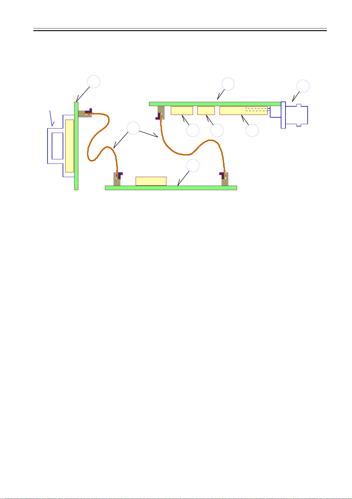
(13) Weight Approx. 12g (Sensor board, Main board)
(14) Lens Mount OLPF and a filter on a sensor board at the time of delivery
(15) Gain Setting AGC (Max. Gain : 0dB~30dB)
MANUAL : 0dB~30dB
(16) Shutter Speed Variable
Range OFF : 1/60(60fps, 59.94fps), 1/50(50fps)
MANUAL : 1/8k, 1/4k, 1/2k, 1/1k, 1/500, 1/250, 1/120, 1/100, 1/60, Open
AUTO : 1/8k s~Open (Upper limit and lower limit can be set.)
(17) White Balance Adjustment
Range
AUTO, AUTO(Outdoor), Preset 7 different kinds, User Preset 1~5, One Push
Preset:
Daylight(5500K), Cloudy(6500K), Shade(8000K), Tungsten(3200K), Fluorescent(White),
Fluorescent(Neutral White), Fluorescent(Daylight) 6500K
(18) DC IRIS output(*1) Auto/Open Selectable. Can be used with electric shutter (With priority to electric shutter).
(19) Auto Exposure Detection Average/Center-Weight/Spot(1/256)/Backlight Compensation
(20) Flicker Cancelling OFF/ON
(21) Edge Enhancement OFF, 1, 2, 3, 4, 5 (typ.3)
(22) Color Saturation Adjustment 0%(B/W)~100%(typ.)~200%
(23) Gamma Compensation Auto Gamma Compensation OFF(γ≒0.45) , ON, ON[Strong]
(24) Contrast Adjustment -2, -1, 0, 1, 2 Selectable (typ.0)
(25) Color Balance Blue/Red:-100~0~100(typ.0) , Green/Magenta:-100~0~100(typ.0)

DCC-HD1 Rev.900-785-30-00
©2013 CIS Corporation. All rights reserved.
5
(26) Black Level Adjustment Level:0~127(typ.0)
(27) Pixel Defect (White spot)
Correction Corrected at factory setting.
(28) Remote Control Operation Cameras can be controlled via RS-232C communications or USB 2.0 Full Speed (12Mbps).
Camera settings can be controlled by control software via PC.
(29) Safety/Quality standards UL: Conform to UL Standard including materials and others.
RoHS: Conform to RoHS
CE and FCC are acquired as VCC-HD1 (chassis typed camera).
(30) Durability (*1)
Vibration Acceleration : 98m/s2 (10G)
Frequency : 20~200 Hz
Direction : X,Y, and Z, 3 directions
Testing time : 120min for each direction
Shock No malfunction shall be occurred with 980m/s2(100G) for ±X,±Y, and ±Z,
6 directions.
(31) Operation environment
(*1) Performance
guaranteed 0 ~+40℃Humidity
20 ~80%RH with no condensation
Operation
guaranteed -5 ~+45℃Humidity
20 ~80%RH with no condensation
※Performance guaranteed: All the specifications specified in this manual is guaranteed under
performance guaranteed temperature.
※Operation guaranteed : All the camera functions operate normally under operation guaranteed
temperature.
(32) Storage Environment (*1) Storage Temperature: -25 ~+60℃, Humidity: 20 ~80%RH with no condensation.
(*1) Applied when embedded in VCC-HD1, chassis typed camera.
<3G-SDI output Level A and Level B>
A difference between Level A and Level B is a way of mapping Y signal and Cb/Cr signal onto 3G-SDI standard signal. The
difference does not affect the resolution of the video signal. Some 3G-SDI receivers correspond to either Level A or B,
whereas other receivers correspond to both Levels, so please set the camera mode to match your 3G-SDI receiver.

DCC-HD1 Rev.900-785-30-00
©2013 CIS Corporation. All rights reserved.
6
6. Part Names and Functions
1. Sensor board (BI-VC01PA)
OLPF and filter case are attached to the sensor board.
Protect the OLPF from dusts.
Has the same serial number as the one on a main board
2. Main board (MB-VC01)
Mainly provided with on-board FPGA and CPU.
Has the same serial number as the one on a sensor board.
3. Driver board (PD-VC01)
Mainly provided with on-board 3G-SDI, HD-SDI drive, and power circuit.
Has the same serial number as the one on a sensor board.
4. FPC (51 pins)
FPCs which connect each board
Boards are connected at the time of delivery.
Sensor board and main board are paired up as the correction data of the sensor is saved in the main board.
5. Electric power supply, USB I/F connector (10 pins)
Power input (DC+12V) and USB I/F signal.
Connect to the power input and USB using the attached 10 pins cable.
6. 3G-SDI/HD-SDI output connector (BNC)
3G-SDI/HD-SDI video-out signal
Connect to the 3G-SDI/HD-SDI monitor using BNC cable.
7. DC IRIS LENS connector (4 pins)
Signal for the DC IRIS LENS
Connnect to the DC IRIS LENS using the attached 4 pins cable. No connection is needed when DC IRIS is not
in use.
8. RS-232C I/F connector (3 pins)
Signal for RS-232C
Connect to the RS-232C using the attached 3 pins cable.
No connection is needed when RS-232C is not in use.
BI-VC01 Board
MB-VC01 Board
PD-VC01 Board
OLPF
Filter Case
BNC (3G,HD-SDI OUT)
1
2
3
4
6
587
CN1
CN1 CN2
CN3 CN4 CN5 CN1 CN2

DCC-HD1 Rev.900-785-30-00
©2013 CIS Corporation. All rights reserved.
7
7. External Connector
7.1. PD-VC01 CN1 (10 pins)
7.2 PD-VC01 CN2 (BNC)
7.3 PD-VC01 CN4 (4 pins)
7.4 PD-VC01 CN4 (4 pins)
型名: BM10B-SRSS-TB (JST)
ピン番号 名称
1 Power IN DC+12V
2 GND
3 N.C.
4 N.C.
5 N.C.
6 N.C.
7 USB_VBUS
8 USB_D-
9 USBD+
10 GND
Model Name BCJ-BPLHA (CANARE)
Pin No.
1 3G-SDI/HD-SDI output
2 GND
Model Name:BM4B-SRSS-TB (JST)
Pin No.
1 IRIS_DUMP+
2 IRIS_DUMP-
3 IRIS_DRIVE-
4 IRIS_DRIVE+
Model Name BM4B-SRSS-TB (JST)
Pin No.
1 RS-232C_TXD
2 RS-232C_RXD
3 GND
1
2
1 4
1 3
110

DCC-HD1 Rev.900-785-30-00
©2013 CIS Corporation. All rights reserved.
8
8. Guideline for Thermal design
This camera is designed for embedding into a chassis, therefore, operating the board itself without heat release will exceed the
tolerance of the operation temperature. The operation temperature will reach 130℃when operating FPGA without casing.
Do not leave it on without casing as it may cause burns and damages to the camera. Please refer to the guideline below for
designing heat dissipation.
8.1. Operating temperature of main parts
Board (ref) Data sheet value Upper limit temperature of
IC package surface
Image sensor BI-VC01PA(IC1) ta=75℃85℃
FPGA MB-VC01(IC1)
tj=85℃80℃
CPU MB-VC01(IC4)
ta=85℃95℃
SDI IC PD-VC01(IC3) ta=85℃95℃
Upper limit temperature of the package is ta+10℃for parts defined “ta” on a data sheet.
As the data sheet value of FPGA says “tj,” upper limit temperature of FPGA shall be 80℃based on the thermal
conductivity of the package and power consumption.
Please release heat so that surface temperature of the IC package on a board in a chassis does not exceed the upper
limit temperature. Please measure the temperature in the usage environment.
Give first priority to the heat dissipation of the FPGA because it is the main heat source.
8.2. Temperature measurement of the surface of the device.
Measure temperature by fixing a thermocouple to the device surface with tape, making a slit in the heat conduction
sheet, and adhering a heat-sink tightly onto it.
(E.g.:Temperature measurement of the surface of FPGA)
8.3. Reference> surface temperature of each device in a CIS chassis(29mm×29mm×77mm)
Ambient
temperature
25℃ 40℃ 45℃
Image sensor 58 73 78
FPGA 55.7 70.7 75.7
CPU 51.7 66.7 71.7
SDI IC 55.1 70.1 75.1

DCC-HD1 Rev.900-785-30-00
©2013 CIS Corporation. All rights reserved.
9
9. Factory Settings
Factory Settings
Video Format Settings 1920 x 1080p @60fps(Level A) 1920 x 1080i @60fps
1920 x 1080p @60fps(Level B)
1920 x 1080p @59.94fps(Level A)
1920 x 1080p @59.94fps(Level B
1920 x 1080p @50fps(Level A)
1920 x 1080p @50fps(Level B)
1920 x 1080i @60fps
1920 x 1080i @59.94fps
1920 x 1080i @50fps
1280 x 720p @60fps
1280 x 720p @59.94fps
1280 x 720p @50fps
Gain Mode Auto, Manual Auto
Manual Gain 0dB~30dB 0dB
Max Gain 0dB~30dB 30dB
Shutter Mode Auto, Manual Auto
Shutter Limit Max Open ~< Shutter Limit Min Open
Shutter Limit Min Shutter Limit Max < ~1/8000 1/8000
Manual Shutter Open~1/8000 Open
Iris Open, Auto Open
Flicker Cancel OFF/ON OFF
AE Mode Average Center-Weight
Center-Weight
Spot
Backlight Compensation
Spot Block X=0~15 , Y=0~15 X=8, Y=8
AE Level 0(%)~100(%) 50(%)
AE Speed 0~100 2
White Balance Settings Auto Auto
Auto(Outdoor)
Daylight(5500K)
Cloudy(6500K)
Shade(8000K)
Tungsten(3200K)
Fluorescent(White)
Fluorescent(Neutral White)
Fluorescent(Daylight)
OnePush
Manual
Preset 1~5
Manual R Gain 0(%)~800(%) 100(%)
Manual B Gain 0(%)~800(%) 100(%)
Noise Reduction OFF, ON OFF
Edge Enhancement OFF, 1, 2, 3, 4, 5 3
Color Saturation 0(%)~200(%) 100(%)
Color Balance Blue/Red -100~100 0
Color Balance Green/Magenta -100~100 0
Pedestal OFF/ON OFF
Pedestal Level 0~127 44
Contrast -2, -1, 0, 1, 2 0
Auto Gamma OFF, ON, ON[Strong] OFF

DCC-HD1 Rev.900-785-30-00
©2013 CIS Corporation. All rights reserved.
10
10. Dimensions

DCC-HD1 Rev.900-785-30-00
©2013 CIS Corporation. All rights reserved.
11
11. Case for Indemnity (Limited Warranty)
We shall be exempted from taking responsibility and held harmless for damage or losses incurred by
the user in the following cases.
zIn case damage or losses are caused by fire, earthquake, or other acts of God, acts by third party,
deliberate or accidental misuse by the user, or use under extreme operating conditions.
zIn case indirect, additional, consequential damages (loss of business interests, suspension of
business activities) are incurred as result of malfunction or non-function of the equipment,
we shall be exempted from responsibility for such damages.
zIn case damage or losses are caused by failure to observe the information contained in the
instructions in this product specification & operation manual.
zIn case damage or losses are caused by use contrary to the instructions in this product
specification & operation manual.
zIn case damage or losses are caused by malfunction or other problems resulting from use of
equipment or software that is not specified.
zIn case damage or losses are caused by repair or modification conducted by the customer or any
unauthorized third party (such as an unauthorized service representative).
zExpenses we bear on this product shall be limited to the individual price of the product.
12. MOS Pixel Defect
MOS pixel defects might be noted with time of usage of the products.
The cause of the MOS pixel defects is the characteristic phenomenon of MOS itself and CIS is
exempted from taking any responsibilities for them.
13. Product Support
When defects or malfunction of our products occur, and if you would like us to investigate on the cause
and repair, please contact your distributors you purchased from to consult and coordinate.
Table of contents
Other CIS Camcorder manuals