Cisco TelePresence MX700 User manual

78-100277-02A0 | 2016 JUNE | © 2016 Cisco Systems, Inc. All rights reserved.
Installation guide
for Cisco TelePresence MX700 Dual Camera
on a free standing oor stand or a oor stand secured to the wall
http://www.cisco.com/go/mx-docs

78-100277-02A0 | 2016 JUNE | © 2016 Cisco Systems, Inc. All rights reserved.
Installation guide for Cisco TelePresence MX700 Dual camera - Floor stand
Page 2
Manpower
We recommend three people working together
to mount the system. Follow local regulations.
Dimensions
Height: 1631 mm / 64.3in.
Width: 2517 mm / 99.1 in.
Depth: 156 or 215 mm / 6.2 or 8.5 in. (wall secured)
920mm / 36.3 in. (free standing)
Weight: 156kg / 344 lb
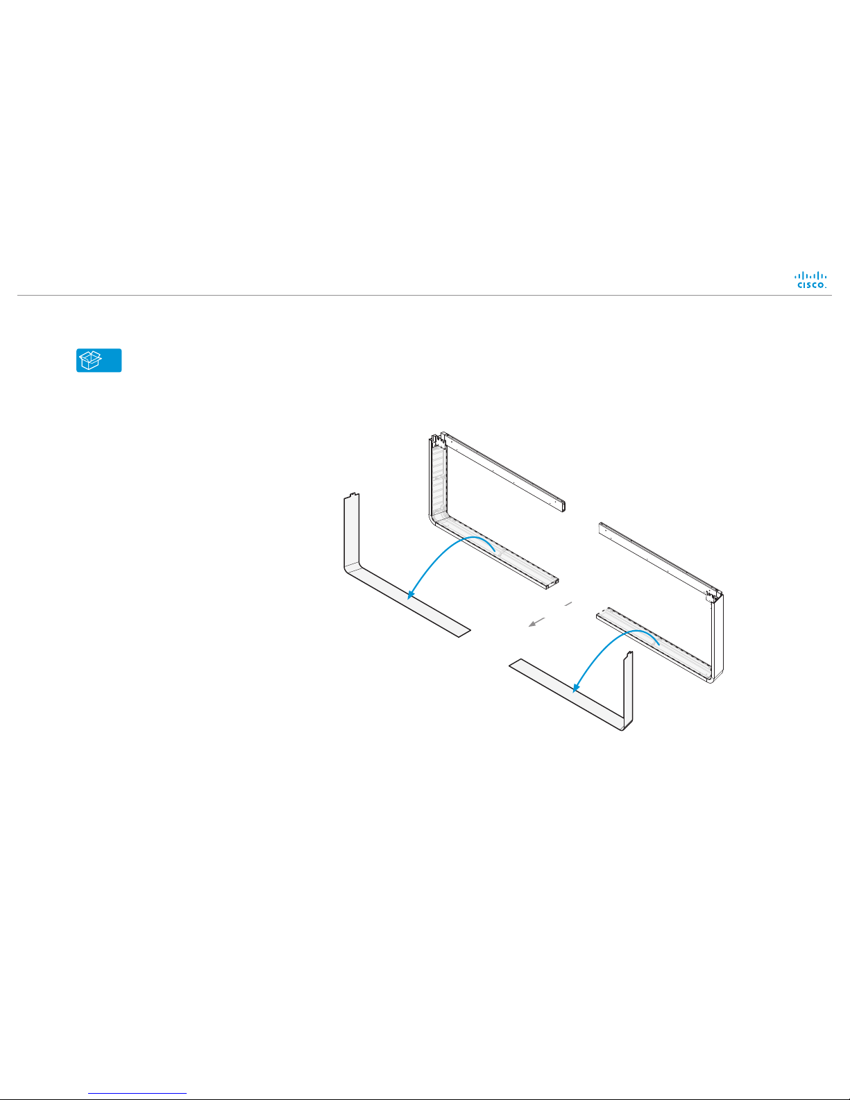
Floor stand secured to the wall
This guide covers the floor stand mounted MX700 with
dual camera, in either the free standing or wall secured
configurations.
Free standing floor stand
Room setup
Explore the Cisco Project Workplace to find
inspiration and guidelines when preparing your
office or meeting room for video conferencing,
http://www.cisco.com/go/projectworkplace
Documentation
Cisco Spark: Visit the Cisco Spark help site to
find more information about Spark registered
room systems, http://help.ciscospark.com
Other services: Visit the Cisco web site
to find user guides and compliance and
safety information for the video system,
http://www.cisco.com/go/mx-docs

78-100277-02A0 | 2016 JUNE | © 2016 Cisco Systems, Inc. All rights reserved.
Installation guide for Cisco TelePresence MX700 Dual camera - Floor stand
Page 3
Lift off box L/M. Lay box A flat on the floor and remove the lid.
2
1Open the plastic snap locks and remove the side walls.
Packaging
L/M
A
D
Boxes are labeled A to M. This guide refers to the labels.
A M
...
B+E-G Shows which boxes are inside.
Tools and screws are in this box.

78-100277-02A0 | 2016 JUNE | © 2016 Cisco Systems, Inc. All rights reserved.
Installation guide for Cisco TelePresence MX700 Dual camera - Floor stand
Page 4
Tools
Allen key, 4 mm
Allen key, 2.5mm
Torx T20
Screws
The screw kit contains more screws than you need,
because the same kit is shipped with all mounting options.
M6x90, countersunk
Tool: Allen key, 4 mm
M6x35, countersunk
Tool: Allen key, 4 mm
M6x12, countersunk
Tool: Allen key, 4 mm
M6x12, pan
Tool: Allen key, 4 mm
M4x8, pan
Tool: Allen key, 2.5mm
PT4x10, pan
Tool: Torx T20
EMC Class A declaration
WARNING: This is a class A product. In a domestic environment this
product may cause radio interference in which case the user may be
required to take adequate measures.
声明
此为A级产品,在生活环境中,该产品可能会造成无线电干扰。在这种
情况下,可能需要用户对其干扰采取切实可行的措施。
WARNING: This is a class A product. In a domestic environment
this product may cause radio interference in which case the user
may be required to take adequate measures.

1Remove covers from floor stand parts
A
78-100277-02A0 | 2016 JUNE | © 2016 Cisco Systems, Inc. All rights reserved.
Installation guide for Cisco TelePresence MX700 Dual camera - Floor stand
Page 5
Set aside the covers. They will be
replaced when the system is fully
assembled and tested (step 20).
Front

2Assemble floor stand
B
78-100277-02A0 | 2016 JUNE | © 2016 Cisco Systems, Inc. All rights reserved.
Installation guide for Cisco TelePresence MX700 Dual camera - Floor stand
Page 6
Fasten the upper and lower center parts
simultaneously, first on one side; then on
the other.
Six screws from the back
and two from the top.
8 × M6x12,
countersunk
8 × M6x12,
countersunk

3Fasten center bracket
78-100277-02A0 | 2016 JUNE | © 2016 Cisco Systems, Inc. All rights reserved.
Installation guide for Cisco TelePresence MX700 Dual camera - Floor stand
Page 7
Front
B
2 × M6x12, pan

4Secure floor stand
B
78-100277-02A0 | 2016 JUNE | © 2016 Cisco Systems, Inc. All rights reserved.
Installation guide for Cisco TelePresence MX700 Dual camera - Floor stand
Page 8
Option A:
Mount the feet to the floor stand to allow it to be free standing.
4 × M6x35,
countersunk
Front
Option B (secured to the wall) is described on the next page.

4Secure floor stand
78-100277-02A0 | 2016 JUNE | © 2016 Cisco Systems, Inc. All rights reserved.
Installation guide for Cisco TelePresence MX700 Dual camera - Floor stand
Page 9
Side view
94 mm / 3.70 in. 37 mm / 1.46 in.
C
Front
The system must be installed by qualified
personnel, in accordance with state and local
building regulations.
The wall and mounting hardware must be
able to safely support the product.
The wall brackets have two mounting positions.
Position the brackets the way that suits your
room the best.
1 2 Place the floor stand in the wall brackets
without fastening it. Move the floor stand and
wall brackets into position.
The wall brackets can be fastened through
any of the horizontal slots. Mark the required
screw hole positions on the wall.
Fasten each wall bracket in a secure manner
ensuring that the wall’s structure is sufficient
to support the system (screws/mounting
hardware not provided; not shown in
illustration).
3Fasten the floor stand to
the wall brackets with the
four screws (provided). 4 × M6x12 (pan)
Option B:
Use the wall brackets provided to secure the floor stand to the wall.
Option A (free standing with feet) is described on the previous page.

5Read this before you mount the monitors
78-100277-02A0 | 2016 JUNE | © 2016 Cisco Systems, Inc. All rights reserved.
Installation guide for Cisco TelePresence MX700 Dual camera - Floor stand
Page 10
The monitors are heavy
We recommend three people
working together to mount the
monitors. Two people should lift
the monitor using the handles as
described here. The other person
must help stabilizing the monitor
and check that the monitor enters
the slots properly.
Use lifting handles
To avoid trapping your fingers, use the
lifting handles at the bottom of the monitor.
The screws with wing nut, which
you can see from the sides of the
monitor, must enter the center slot
on each side of the lower frame.
Applies to systems that are secured to
the wall: To assure that the camera can
move freely, fasten two bump-ons on
the rear of the top profile, close to the
camera.

6Lift left monitor onto floor stand
D
78-100277-02A0 | 2016 JUNE | © 2016 Cisco Systems, Inc. All rights reserved.
Installation guide for Cisco TelePresence MX700 Dual camera - Floor stand
Pag e 11
65 kg / 144 lb
Make sure that the screw
with wing nut enters the
center slot on both sides.
Do not let go of the monitor
before it is securely placed
on the floor stand.
1
Rear view
Tighten the wing nuts
on both sides. They are
accessed from the sides
of the monitor.
2
Rear view

7Fasten left monitor to floor stand and connect power cable
78-100277-02A0 | 2016 JUNE | © 2016 Cisco Systems, Inc. All rights reserved.
Installation guide for Cisco TelePresence MX700 Dual camera - Floor stand
Page 12
Enter four screws from
front and four screws from
underneath. Then, tighten
all screws.
1
Connect power cable
A power cable is strapped at the
rear of the monitor. Connect it to the
close-by socket.
Let the other end hang freely. It will
be connected to the right monitor in
step 9.
2
4 × M6x90,
countersunk
4 × M6x35,
countersunk

8Lift right monitor onto floor stand
D
78-100277-02A0 | 2016 JUNE | © 2016 Cisco Systems, Inc. All rights reserved.
Installation guide for Cisco TelePresence MX700 Dual camera - Floor stand
Page 13
65 kg / 144 lb
Tighten the wing nuts
on both sides. They are
accessed from the sides
of the monitor.
2
Make sure that the screw with
wing nut enters the center slot on
both sides.
Keep the outer side a bit lower than
the side toward the other monitor
when lowering the monitor onto the
floor stand.
Do not let go of the monitor before it
is securely placed on the floor stand.
1Rear view
Rear view

9Fasten right monitor to floor stand and connect power cable
78-100277-02A0 | 2016 JUNE | © 2016 Cisco Systems, Inc. All rights reserved.
Installation guide for Cisco TelePresence MX700 Dual camera - Floor stand
Pag e 14
Enter four screws from
front and four screws from
underneath. Then, tighten
all screws.
1
Connect power cable
Connect the loose end of
the power cable from step
10 to the close-by socket at
the rear of the right monitor.
The socket must be reached
from below.
Make sure that the power
switch next to the socket is
in its ON position.
2
4 × M6x90,
countersunk
4 × M6x35,
countersunk

10Remove support handles
78-100277-02A0 | 2016 JUNE | © 2016 Cisco Systems, Inc. All rights reserved.
Installation guide for Cisco TelePresence MX700 Dual camera - Floor stand
Page 15
Unscrew the screws (4 × M4x8)
and remove the support handles.
1Unscrew the screws (2 × M4x8)
and remove the brackets that the
support handles were fastened to.
2

11 Mount joining bracket
E
78-100277-02A0 | 2016 JUNE | © 2016 Cisco Systems, Inc. All rights reserved.
Installation guide for Cisco TelePresence MX700 Dual camera - Floor stand
Page 16
Box E is placed underneath box C.
7 × M6x12, pan
Place the joining bracket in the
channel. Make sure it aligns with
the channel at top.
Open the lever.
Push down the lever to
horizontal position.
12
3 4

12 Mount back cover
E
78-100277-02A0 | 2016 JUNE | © 2016 Cisco Systems, Inc. All rights reserved.
Installation guide for Cisco TelePresence MX700 Dual camera - Floor stand
Page 17
1
2
Lower the back cover toward the
system. The cover snaps to magnets.
Lead the guidance pins on the back
cover into the holes.
Mount the back cover. If the system is
placed close to the wall the back cover
must be mounted from above.

13Organize pre-mounted cables
78-100277-02A0 | 2016 JUNE | © 2016 Cisco Systems, Inc. All rights reserved.
Installation guide for Cisco TelePresence MX700 Dual camera - Floor stand
Page 18
Organize the cables that are placed in the channel on top of the monitors. Lead the cables to
the right, and place them as shown in the illustration.
Note that the loudspeaker cable 4 above the right monitor will not be used.
The camera module will be connected in step 15 and the cables will be connected in steps 14,
16 and 17.
Right
monitor
On the right side of monitor
Power over Ethernet
(step 14)
To the left of camera module Camera cables
Power (step 16)
Ethernet (step 16)
Loudspeaker cables
number 3–4 (step 17)
2 × HDMI (step 14)
USB, type B (step 14)
HDMI (step 16)
To the right of camera module
Loudspeaker cables
number 1-3, 5 (step 17)
4 ×
Loudspeaker cable
number 5 (step 17)

14 Connect cables to right monitor and PoE injector
78-100277-02A0 | 2016 JUNE | © 2016 Cisco Systems, Inc. All rights reserved.
Installation guide for Cisco TelePresence MX700 Dual camera - Floor stand
Page 19
Power over Ethernet injector
Ethernet
Right monitor connector panel
HDMICOLOR
CALIBRATION 12
DO NOT
REMOVE
USB (type B)HDMI
SWITCH

15Mount camera module (page 1 of 2)
F, G
78-100277-02A0 | 2016 JUNE | © 2016 Cisco Systems, Inc. All rights reserved.
Installation guide for Cisco TelePresence MX700 Dual camera - Floor stand
Page 20
Make sure that the HDMI
cable for the left camera and
loudspeaker cable 5 can be
accessed through the hole in the
bottom plate of the camera module.
Check that no cables are pinched
when the camera module is inserted.
4 × M4x8, pan
Fasten the stud with one screw to
the upper right corner of the right
camera. Repeat this step for the
upper left corner of the left camera.
Fasten each stud to the top profile
with two screws from underneath.
3 × M4x8, pan
123
Other manuals for TelePresence MX700
7
Table of contents
Other Cisco Camcorder manuals