Cisco TelePresence SpeakerTrack 60 User manual

Cisco TelePresence
SpeakerTrack 60
INSTALLATION GUIDE
The SpeakerTrack 60 uses a unique dual-camera
technique to quickly view a close-up of the active
speaker in the meeting room.
78-100223-02C0 | MARCH 2015.
Copyright © 2015 Cisco Systems, Inc. All rights reserved.

78-100223-02C0 | MARCH 2015.
Copyright © 2015 Cisco Systems, Inc. All rights reserved.
Installation
We invite you to explore the Project Workplace guide to inspire you on room design and room
setup. Go to: www.cisco.com/go/projectworkplace
Main box contents
A. 1 × Cover plate
B. 1 × Microphone panel with four
biult-in microphones
C. 2 × Precision 60 Camera
D. 1 × Base unit, with connectors
1 × Accessories box
1 × Installation Guide
Accessories
E. 2 × Camera interface plate
F. 1 × Wall bracket
G. 1 × DC Power cable w/ barrel plug,
20 cm / 7.87 in
H. 1 × DC Power cable w/ barrel plug,
45 cm / 17.72 in
I. 1 × Ethernet cable, 20 cm / 7.87 in
J. 1 × Ethernet cable, 35 cm / 13.78 in
K. 1 × Power adapter and power cable
L. 1 × Gloves
M. 1 × Torx Key (T20)
N. 1 × Allen Key
O. 2 × Thumb nut, M4
P. 4 × Pan headed screw, M4 16 mm
Q. 2 × 1/4” UNC screw
R. 1 × Template for attaching the
wall bracket (not shown)
B
D
FE
G
I
H
J
C
A
K
L NM
O QP

78-100223-02C0 | MARCH 2015.
Copyright © 2015 Cisco Systems, Inc. All rights reserved.
Safety instructions
NOTE: It is of great importance that the wall mount unit is safely installed, that the wall is able to
support the product and that the screws or mounting means used are suitable for the wall and
the weight of the product.
NOTE: According to the relevant international safety standard for IT products the wall is required
to support four times the actual load, which implies that the SpeakerTrack 60 must be mounted to
a wall which supports at least: 4 × 11.25 kg = 45 kg (4 × 24.8 lbs = 99.2 lbs).
NOTE: This type of equipment is to be installed by the submitter’s/dealer’s qualied installer.
The installer is responsible for obtaining safety inspection of the structural integrity of the
installation by the local authority/inspection department.
NOTE: Note that the surface is hot when the camera is in operation.
WARNING: Use Ethernet cable only when connecting to the Ethernet port on the
camera. Do not connect a serial VISCA cable to the Ethernet port on the camera, as
this will cause severe damage to the camera.

78-100223-02C0 | MARCH 2015.
Copyright © 2015 Cisco Systems, Inc. All rights reserved.
Room guidelines
The participants should be seated within the horizontal eld of view (HFOV) and within the
maximum microphone range. In acoustically dampened rooms, the SpeakerTrack 60 can be
used at the full eective range. In less dampened rooms, the performance may be decreased.
Minimum distance to the side
walls 120 cm / 47.25 in
Maximum microphone
range 900 cm / 354 in
HFOV 80°
Top view of a room with SpeakerTrack 60. For optimal audio tracking the SpeakerTrack
should be mounted at some distance from the side walls.

78-100223-02C0 | MARCH 2015.
Copyright © 2015 Cisco Systems, Inc. All rights reserved.
Mounting the unit above the monitor
Having eye contact with remote participants is essential for a good user experience, and therefore
you should consider if SpeakerTrack 60 should be mounted above or below the monitor.
NOTE: Obstacles placed in front of the microphone panel, or in the sight line of the
microphones, will cause severe loss in the speaker track performance.
Side view of a room with SpeakerTrack 60 mounted above the monitor. For optimal audio
tracking the SpeakerTrack should be mounted at some distance to the ceiling.
Select a mounting height for SpeakerTrack 60 that provides
clear line of sight, to all four edges of the microphone panel,
from all appropriate positions in the meeting room.
Minimum distance to the
ceiling 40 cm / 15.75 in

78-100223-02C0 | MARCH 2015.
Copyright © 2015 Cisco Systems, Inc. All rights reserved.
Mounting in a recess above the monitor
SpeakerTrack 60 is designed to be wall mounted. If mounted in a recess, the sound from any
participant in the room must reach at least three of the four microphones on the microphone
panel. To obtain this, the recess should be constructed with sloping walls.
CAD drawings with details and dimensions: http://www.cisco.com/go/telepresence/docs and
navigate to: Collaboration Endpoints > Collaboration Peripherals > TelePresence Peripherals >
TelePresence SpeakerTrack 60 > Technical References
• The bottom wall of the recess is sloped 17°
• The side walls of the recess are sloped 45°
• The maximum depth of the recess is 217.6 mm (8.56 in). If less depth the camera will
protrude from the wall. Follow local building regulations and accessibility requirements.
820 mm (32.3 in)
320 mm
(12.6 in)

78-100223-02C0 | MARCH 2015.
Copyright © 2015 Cisco Systems, Inc. All rights reserved.
Side view of a room with SpeakerTrack 60 mounted beow the monitor. For large monitors
(70” and above), we recommend mounting the SpeakerTrack below the monitor.
Select a mounting height for SpeakerTrack 60 that provides
clear line of sight, to all four edges of the microphone panel,
from all appropriate positions in the meeting room.
Mounting the unit below the monitor
Having eye contact with remote participants is essential for a good user experience, and therefore
you should consider if SpeakerTrack 60 should be mounted above or below the monitor.
NOTE: Obstacles placed in front of the microphone panel, or in the sight line of the
microphones, will cause severe loss in the speaker track performance.

78-100223-02C0 | MARCH 2015.
Copyright © 2015 Cisco Systems, Inc. All rights reserved.
Mounting in a recess below the monitor
SpeakerTrack 60 is designed to be wall mounted. If mounted in a recess/box, the sound
from any participant in the room must reach at least three of the four microphones on the
microphone panel. To obtain this the recess/box must be constructed with inclined walls.
CAD drawings with details and dimensions: http://www.cisco.com/go/telepresence/docs and
navigate to: Collaboration Endpoints > Collaboration Peripherals > TelePresence Peripherals >
TelePresence SpeakerTrack 60 > Technical References
820 mm (32.3 in)
320 mm
(12.6 in)
• The upper wall of the recess is sloped 17°
• The side walls of the recess are sloped 45°
• The maximum depth of the recess is 217.6 mm (8.56 in). If less depth the camera will
protrude from the wall. Follow local building regulations and accessibility requirements.

78-100223-02C0 | MARCH 2015.
Copyright © 2015 Cisco Systems, Inc. All rights reserved.
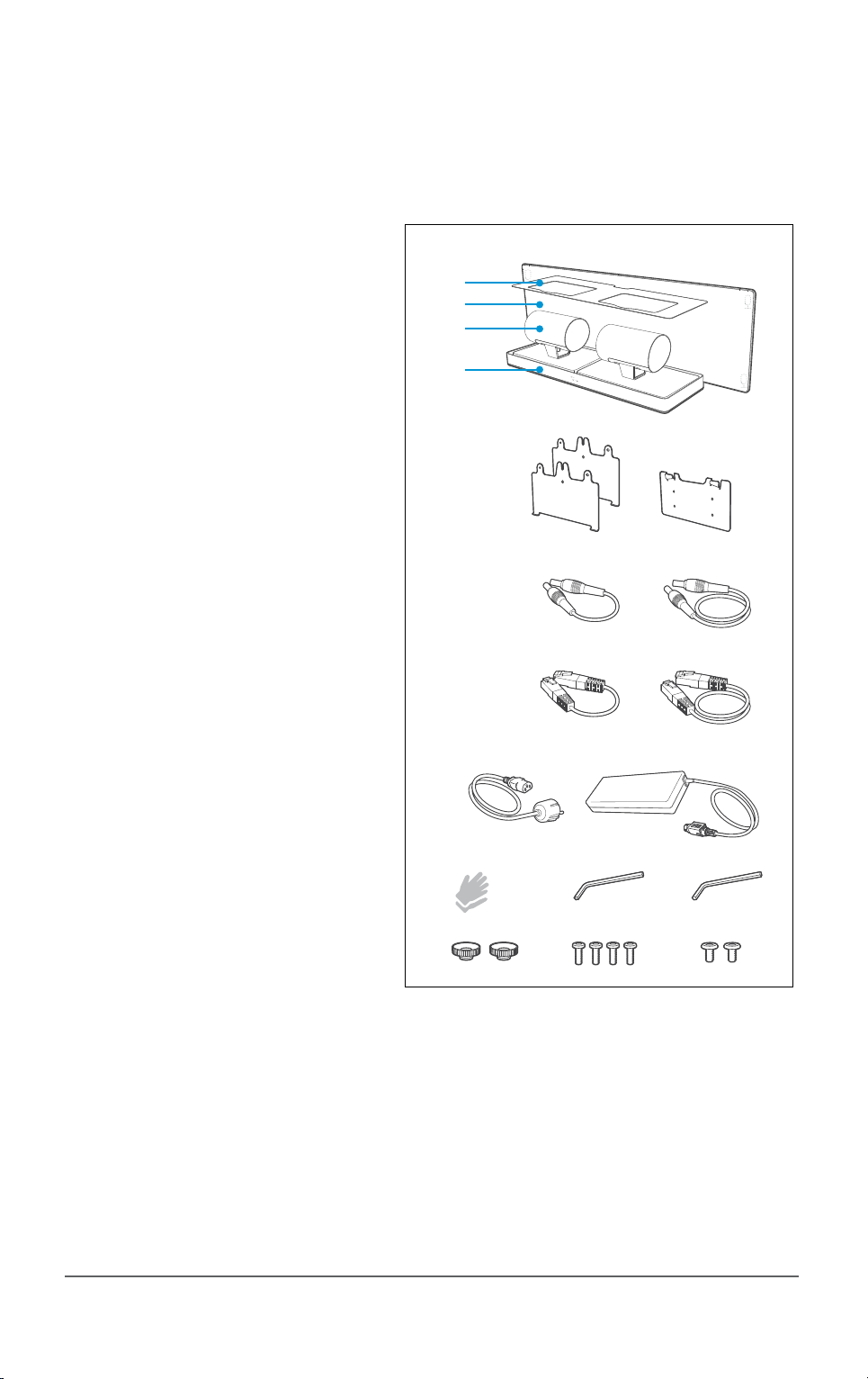
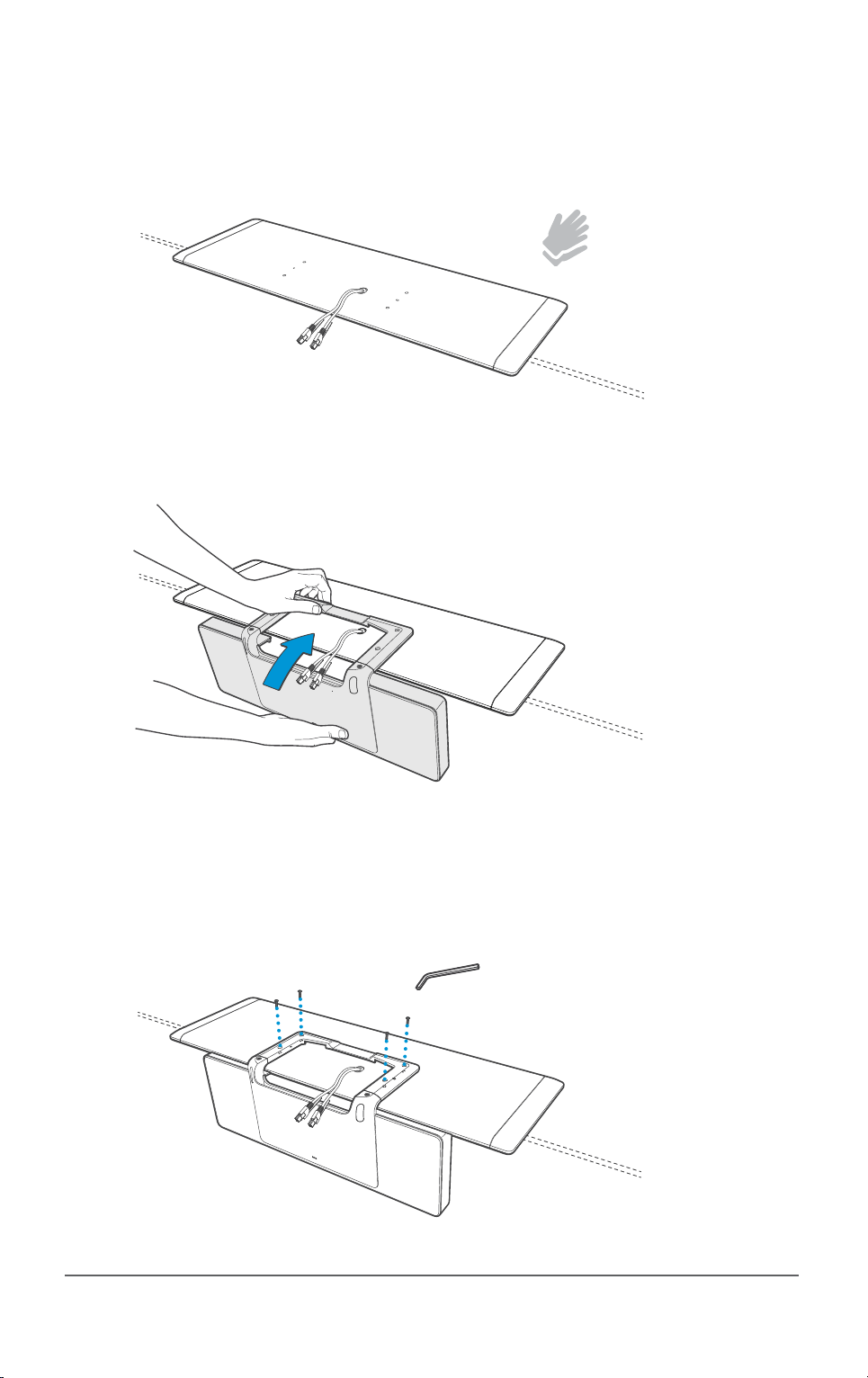
Mounting the wall bracket
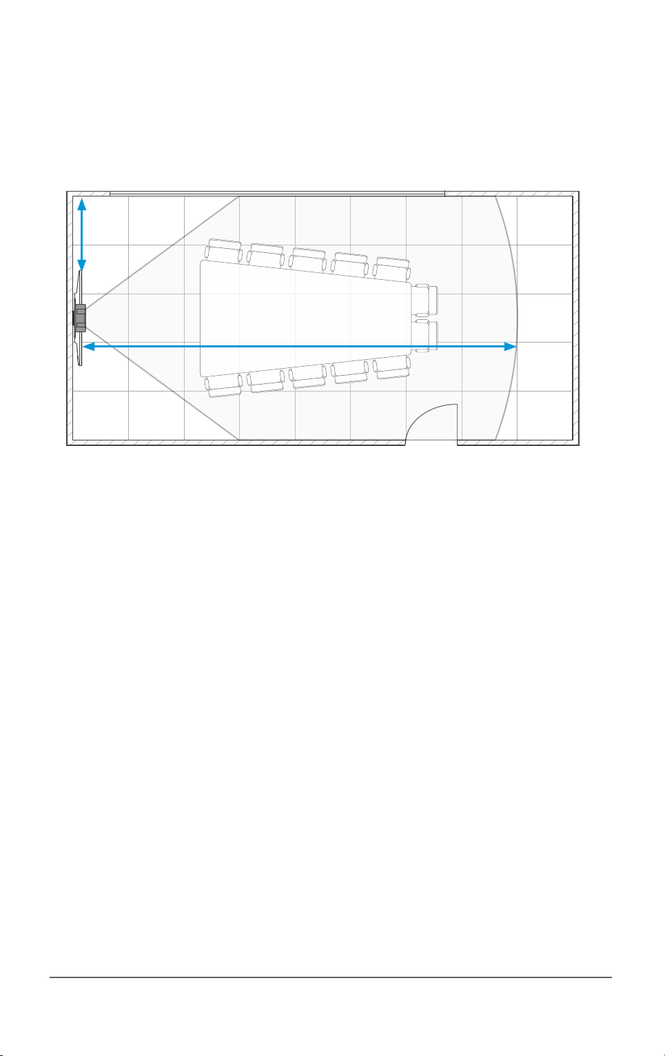
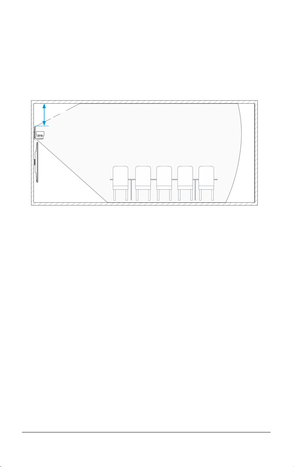
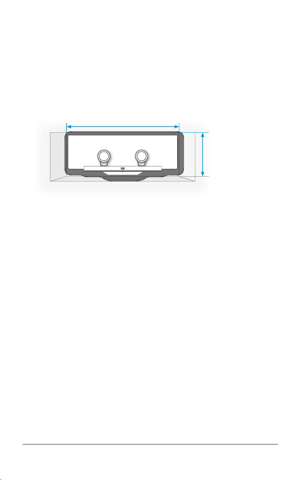
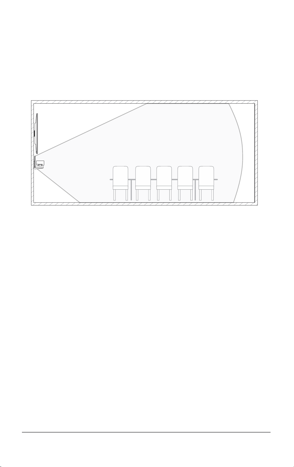
NOTE: Read the room guidelines, mounting guidelines and safety instructions before you start
mounting the wall bracket (F). Use the Template for attaching the wall bracket (R), found with
the accessories, and follow the instructions on the template when mounting the wall bracket.
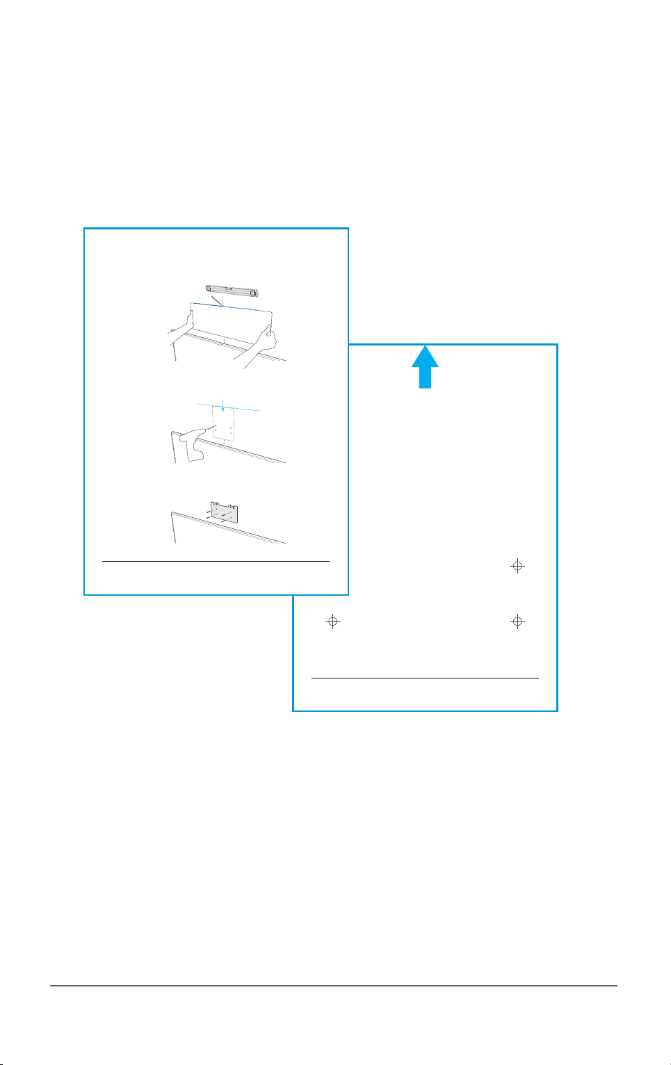
Template, page 1 (found with the accessories)
Template, page 2
78-100272-01A0 | FEBRUARY 2014.
Copyright © 2014 Cisco Systems, Inc. All rights reserved.
M6
78-100272-01A0 | FEBRUARY 2014.
Copyright © 2014 Cisco Systems, Inc. All rights reserved.
M6
Template for attaching wall bracket for SpeakerTrack 60
Gabarit de xation du support mural pour SpeakerTrack 60
Check that the unit is level.
Vériez que l’appareil est à niveau.
SpeakerTrack 60
rear panel
SpeakerTrack 60
panneau arrière
The monitor
center point
Template for drilling holes
(found overleaf)
Modèle pour les trous de forage
(qui se trouve au verso)
Wall bracket
Support mural
Find the center point of the
monitor and the top center point of
the SpeakerTrack 60 rear panel.
Localisez le centre du moniteur
et le centre supérieur du
SpeakerTrack 60.
Use the template on the other side of
this sheet when drilling holes for the
wall bracket. Screw dimension M6.
Utilisez le modèle au verso de cette
page pour le perçage des trous de la
xation murale. Vis dimension M6.
Select the type of attachment for
the wall bracket on the basis of the
type of material the wall is made of
(wood, concrete, gypsum).
Sélectionnez le type de xation du
support mural en fonction du type
de matériau du mur (bois, ciment,
gypse).

78-100223-02C0 | MARCH 2015.
Copyright © 2015 Cisco Systems, Inc. All rights reserved.
Mounting the base unit
Place the microphone panel (B) on a clean and stable surface (for example a table) with the
microphone cables headed up and the textile headed down.
Remove the cover plate (A) from the base unit before this
operation. Hold the base unit (D) as illustrated and slide in
place. Make sure the guide-pins positions correctly.
Use the four pan headed screws (P) when fastening the base unit.
Use the Torx Key (M) and tighten the screws.
Use the supplied
gloves (L).

78-100223-02C0 | MARCH 2015.
Copyright © 2015 Cisco Systems, Inc. All rights reserved.
Mounting the cables
Connect the cables to the connector panel on the base unit:
1. Find the Ethernet cables (I, J) and the power cables (G, H) in the accessories box. Connect
the short cables to the connectors marked R ( ) and the long cables to the connectors
marked L ( ). Lead them through the open slot to make them available for camera
mounting.
2. Connect the microphone cables coming from the microphone panel.
3. Find the power adapter and the power cable (K) in the accessories box. Connect the power
cable to the base unit.
4. Connect an Ethernet cable (not included) to the Ethernet port on the base unit. Connect
the other end directly to the codec. If you do not have any free Ethernet port on the codec
(typically if a Touch device is connected) you will need a network switch. Connect the
switch to the Ethernet port on the codec, and connect the Touch device and SpeakerTrack
60 to the switch. We recommend using a Cisco switch.
1 2
3 4
Connect the short Ethernet and
power cables to the right camera,
and the long Ethernet and power
cables to the left camera.
Connect the microphone
cables that comes from the
microphone panel.
Connect the Ethernet
cable (not included)
directly to the codec
(Eth2/Eth3).
Connect the
power cable.
Rear view

78-100223-02C0 | MARCH 2015.
Copyright © 2015 Cisco Systems, Inc. All rights reserved.
Mounting the assembly to the wall
Hold and lift the unit as illustrated. Carefully place the unit onto the wall bracket.
Check that the unit is level. If not,
you can adjust the unit sideways.

78-100223-02C0 | MARCH 2015.
Copyright © 2015 Cisco Systems, Inc. All rights reserved.
Mounting the interface plate
Place the camera (C) on a stable surface as illustrated. Use the 1/4” UNC screw (Q) and Allen
Key (N) and mount the camera interface plate (E) to the camera.
Repeat these steps for the second camera (C).

78-100223-02C0 | MARCH 2015.
Copyright © 2015 Cisco Systems, Inc. All rights reserved.
Connecting the camera cables
It can be a bit cramped when you connect and secure the cameras, so you’ll probably
want to inspect the camera connector panel to know where the HDMI, Ethernet and power are
located.
Start with the camera to the right and hold the camera as illustrated. Make sure the short cables
(Ethernet and power) are available for this camera and connect the cables. Then connect the
HDMI cable coming from the codec. Guide the camera into position.
Proceed with the camera to the left and hold the camera the same way as you did with the rst
camera. Connect the long cables (Ethernet and power) to the left camera. Connect the HDMI
cable coming from the codec. Guide the camera into position.
3,0A
Connect one HDMI cable
to each camera. The HDMI
cables for the two cameras
are going to the codec.
The Ethernet and power
cables are coming from the
base unit. The short cables
goes to the right camera and
the longer cables to the left
camera.
Right
side
Left
side

78-100223-02C0 | MARCH 2015.
Copyright © 2015 Cisco Systems, Inc. All rights reserved.
Fastening the cameras
Make sure the pins on the base plate ts the holes in the camera interface plate.
Use the thumb nut (O) to
attach the camera to the
base. Repeat this step for
the second camera.
Make sure the pins on the
base plate ts the holes in
the camera interface plate.

78-100223-02C0 | MARCH 2015.
Copyright © 2015 Cisco Systems, Inc. All rights reserved.
Finishing up
• Move the two cameras into standby position as illustrated and carefully slide the cover
plate (A) on place.
• Use a cable management for a good aesthetic appearance.
• Connect the Ethernet and HDMI cables to the codec, see the codec documentation for
further information.
• Connect the power cable to the power mains.
HDMI
left
camera
Ethernet Power HDMI
right
camera

78-100223-02C0 | MARCH 2015.
Copyright © 2015 Cisco Systems, Inc. All rights reserved.
User documentation and support
User documentation for SpeakerTrack 60:
http://www.cisco.com/go/telepresence/docs
Navigate to: Collaboration Endpoints > Collaboration Peripherals >
TelePresence Peripherals > TelePresence SpeakerTrack 60
For support, go to: http://www.cisco.com/support

78-100223-02C0 | MARCH 2015.
Copyright © 2015 Cisco Systems, Inc. All rights reserved.
Find an overview of the Cisco oces on our web site.
http://www.cisco.com/go/oces
Cisco and the Cisco logo are trademarks or registered trademarks of Cisco and/or its aliates in the U.S. and
other countries. To view a list of Cisco trademarks, go to this URL: www.cisco.com/go/trademarks. Third-party
trademarks mentioned are the property of their respective owners. The use of the word partner does not imply a
partnership relationship between Cisco and any other company. (1110R)
Other manuals for TelePresence SpeakerTrack 60
3
Table of contents
Other Cisco Speakers manuals