City Theatrical AUTOYOKE User manual

TABLE OF CONTENTS
SECTION 1 SPECIFICATIONS
1-1 Dimensions and Weight
1-2 Compliance
1-3 Electrical
1-4 Protocol
1-5 Motors
SECTION 2 SAFETY
SECTION 3INSTALLATION AND SET-UP
3-1 Unpack and inspect the shipping container
3-2 Placing a lighting fixture in the AutoYoke
3-3 Installing the fixture power connector on the AutoYoke
3-4 Attaching a scroller
3-5 Inserting the DMX Iris
3-6 AutoFocus
3-7 Changing Lens Tubes
3-8 Securing the counterweight system
3-8 Hanging the AutoYoke
3-9 Power cable
3-10 Data cable
SECTION 4USER INTERFACE
4-1 Menu system
4-2 Address
4-3 Calibrate
4-3a Calibrate All
4-3b Calibrate a single attribute
4-3c AutoCalibrate
4-4 Invert
4-5 Resolution
4-5a 8 bit or 16 bit
4-5b DMX Smoothing values
4-6 Pan, Tilt, Iris and Focus Limits
4-7 Software release
4-8 LED Display
4-8a Timeout
4-8b Brightness
4-9 Restore factory defaults
4-10 Error messages
p. 1
p. 2
p. 2
p. 2
p. 2
p. 3
p. 4
p. 5 - 9
p. 9
p. 10
p. 11
p. 12
p. 13
p. 14
p. 15
p. 15
p. 15
p. 16
p. 17
p. 18
p. 18
p. 19
p. 19 - 20
p. 20 - 21
p. 21
p. 22
p. 22
p. 23 - 24
p. 25
p. 25
p. 26
p. 26
p. 26
p. 27

SECTION 5OPERATION
5-1 DMX channel assignments
5-2 Pan and Tilt
5-3 Default setting
5-4 Personality settings
5-5 Control channel
5-6 Encoders
SECTION 6BEAM SIZE AND COLOR CONTROL
DMXIris
AutoFocus
Scrollers
SECTION 7MAINTENANCE
Software revisions
Spare parts
Lighting fixture
SECTION 8 WARRANTY
Limited Warranty
Procedure
p. 28
p. 28
p. 29
p. 29
p. 30
p. 30
p. 31
p. 31
p. 31
p. 32
p. 32
p. 32
p. 32
p. 32
SECTION 1: SPECIFICATIONS
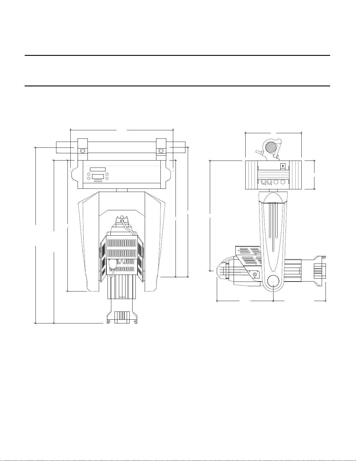
1-1DIMENSIONS & WEIGHT
AutoYoke weight: 26 lbs (11.7 kg)
Total weight ofAutoYoke with Source Four:40 lbs (18 kg)
-1-
***Note: AutoYoke is shown with ETC Source Four and Light Source “Mega Claw” clamps
s
t
Menu
Enter
AUTOYOKE
CITY
THEATRICAL
I N C
10"
5-3/8"
9-1/8" Lens tube in
11-1/4" Lens tube out
10-1/2"
21-1/2"
20-7/8"
22"
25"
24-1/8"
29-1/4"
Lens tube in
31-3/8"
Lens tube out
32-1/4"
Lens tube in
34-3/8"
Lens tube out

1-2COMPLIANCE
Conforms to UL STD 73, Eighth Edition - Motor Operated Appliances.
Certified to CAN/CSA C22.2 NO.: 68.92
ETL# 9801635
CETL# 9801635
CE, GS,
1-3ELECTRICAL
· Working voltage: 100-240 VAC, 50/60 Hz
· Rated current: 1.3A
1-4PROTOCOL
· USITT DMX512
· Start code: (00h)
· Maximum load: 32 fixtures per DMX link (See Section 3-9, Data Cable)
· Maximum length of DMX link: 2000'(See Section 3-9, Data Cable)
· Required control channels: 7 (16-bit) or 5 (8-bit)(See Section 3-9, Data Cable)
· Termination: 120Ω(See Section 3-9, Data Cable)
1-5MOTORS
· High torque stepper motor, half stack
· Rated voltage DC: 8.7
· Step angle (degrees): 1.8
-2-

SECTION 2: SAFETY
· A moving light is a dangerous piece of equipment. It is for professional use only.
· If the supply cord is damaged, it must be replaced by the manufacturer or its service agent or a similarly
qualified person in order to avoid a hazard.
· Follow all safety procedures that apply to the lighting fixture, per its manufacturer’s instructions.
1. Refer to the lighting fixture’s user manual for all applicable safety information.
2. Maintain minimum safe distances.
· The AutoYoke is designed for use only with the ETCSource Four 5°, 10°, 19°, 26°, 36° or 50°
Using a fixture other than the ETC Source Four 5°, 10°,19°, 26°, 36° or 50° WILL VOID THE
AUTOYOKE WARRANTY.
· Always ground (earth) the AutoYoke electrically.
· Balance of the lighting fixture as mounted in the AutoYoke is critical to proper operation of the AutoYoke.
Attempting to operate the AutoYoke while the lighting fixture is out of balance presents a significant risk
of inaccuracy, increased motor noise and component failure. See Section 3-7, Securing the
Counterweight System, for complete information.
· Never lift the AutoYoke by the lighting fixture. Always lift and carry the AutoYoke by its two
handles, located on the sides of the power supply.
· Always suspend the AutoYoke from approved clamps secured to the designated points on the AutoYoke
power supply. See Section 3-8, Hanging the AutoYoke, for further information.
· Always use an approved safety cable when hanging the AutoYoke.
· Always disconnect the AutoYoke from AC power before service.
· Do not use DMX accessories that are not cited in this manual due to possible electrical incompatibility
with the AutoYoke.
· Do not allow the AutoYoke or its accessories to come into contact with moisture.
· Do not put flammable materials on or near the AutoYoke.
-3-

SECTION 3: INSTALLATION AND SET-UP
WARNING:Using a fixture other than the ETC Source Four 5°,10°,19°, 26°, 36° or 50°
with the AutoYoke WILL VOID THE AUTOYOKE WARRANTY.
Additional hazards include the following:
· Damaging both the AutoYoke and the lighting fixture
· Fixture detaching from the AutoYoke
· Fire hazard
3-1UNPACK AND INSPECT THE SHIPPING CONTAINER
Verify that the AutoYoke has arrived complete and undamaged. The shipping container will contain the
following items:
· (1) AutoYoke w/ User’s Manual
· (1) counterweight halo
· (10) counterweight rings [8 lead, 2 steel]
· (2) lighting fixture mounting screws [5/16 - 18 x 1/2” flanged button head screws]
· (2) Counterweight halo mounting screws [1/4 - 20 - 3/4” socket head cap screws]
· (3) Counterweight ring mounting screws [1/4 - 20 - 1” socket head cap screws]
· (3) Counterweight ring mounting screws [1/4 - 20 - 2” socket head cap screws]
CITY
THEATRICAL
I N C
s
A U T O Y O K E
t
Enter
Menu
Lumen
-4-
Source Four
cradle
connector box
counterweight halo
yoke
control panel
handle
power supply
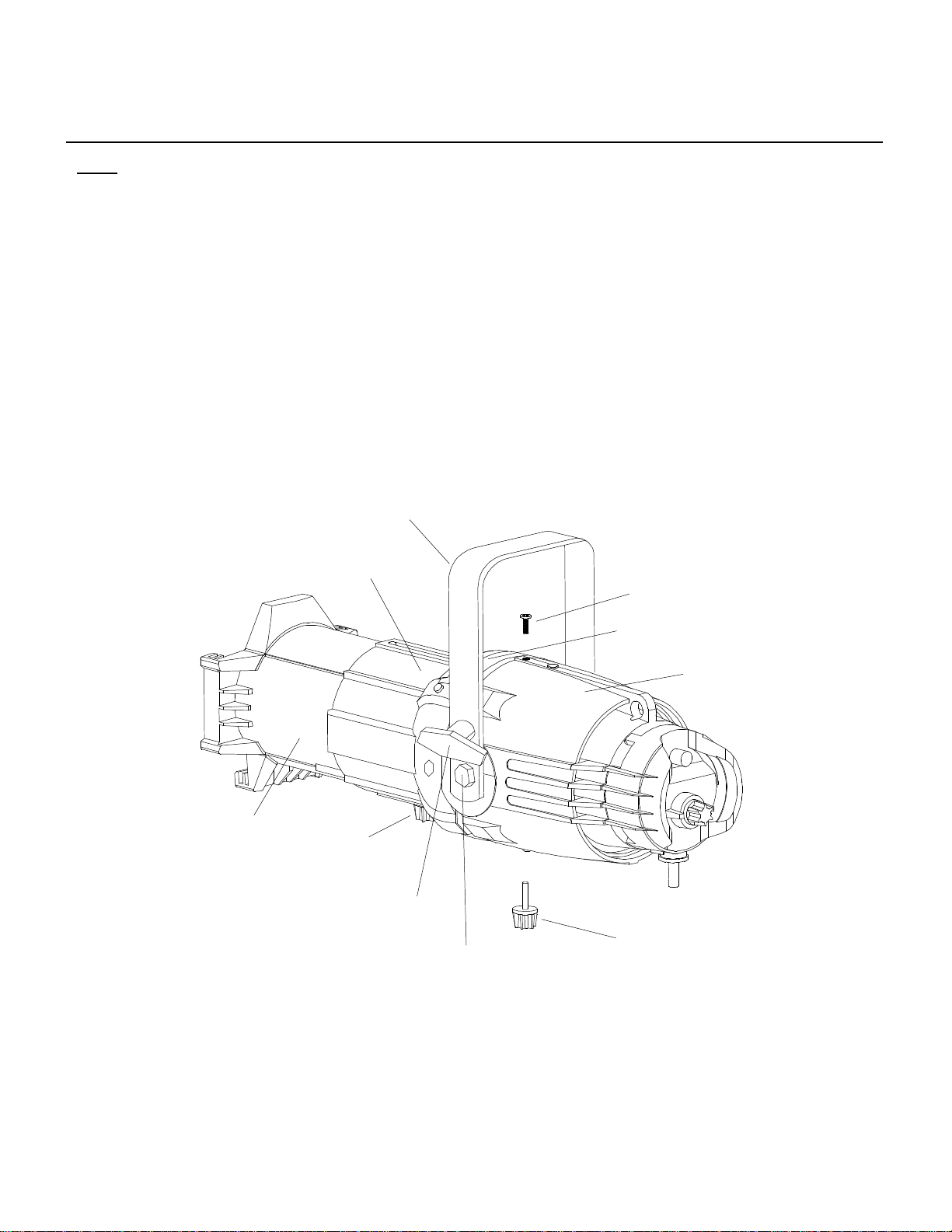
3-2PLACING A LIGHTING FIXTURE IN THE AUTOYOKE
*NOTE: SOURCE FOUR FIXTURES THAT WERE MANUFACTURED BEFORE JULY 1995 DO NOT HAVE A
THREADED HOLE FOR THE “RETAINER BOLT” AS IN EXAMPLE 1 BELOW. THEY ONLY HAVE A
“BARREL ROTATION KNOB”, INSTALLATION OF THESE UNITS WILL REQUIRE MODIFICATION FOR
PROPER MOUNTING TO THE AUTOYOKE. CONTACT CITY THEATRICAL, INC. FOR A MODIFICATION KIT.
1. Remove all accessories from the lighting fixture (scroller, gel frame, top hat, etc.)
2. On the lighting fixture, remove the yoke by removing the yoke locking knob and the two hex bolts that
are on either side of the lighting fixture.
-5-
yoke
hex bolt
yoke locking knob
beam focus knob
lens tube
front barrel assembly
barrel rotation knob
reflector housing assembly
iris slot
retainer bolt
EXAMPLE 1

3.Remove the Source Four shutters with the following instructions:
a. Remove the lens tube from the front barrel assembly by
removing the beam focus knob.
b.Untwist and remove the Source Four front barrel
assembly from the reflector housing assembly by loosening
the barrel rotation knob and removing the retainer bolt.
c.Lay the front barrel assembly on its side, with the iris slot
pointing up.
d.Remove the four pan head 8-32 x 3/4” screws and 8-32
Ny-lok nuts that fasten the top and bottom barrel casting.
Remove the four shutter springs. Always wear protective
eyewear during this procedure, as the springs may pop
out of place.
e.Separate the top and bottom barrel casting, and remove the
four shutter blades. Keep the three divider plates in the
same position relative to each other and the SourceFour
(refer to Source Four user manual for further details).
f.Rejoin the top and bottom barrel casting. Starting at the
holes closest to the shutters, use the four pan head screws
and Ny-lok nuts to fasten the front barrel casting halves
together. Hold the Ny-lok nuts tight against the casting while
tightening the screws. Torque the screws to 25 inch/pounds
[From Source Four Parts and Assembly Instructions
published by ETC].
g.Insert the four shutter springs between the four dimples in
the shutter plate and the tabs in the lip of the casting.
Always wear protective eyewear during this procedure, as
the springs may pop out of place [From Source Four Parts
and Assembly Instructionspublished by ETC].
h.Twist and re-insert the front barrel assembly into the
reflector housing assembly, and fasten by inserting the
barrel rotation knob into the hole from which you previously
removed the retainer bolt (Example 2). Do not re-insert
the retainer bolt at this time. It will be used shortly.
i. Re-insert the lens tube into the front barrel assembly, and
fasten by tightening the beam focus knob.
-6-

4. Tighten the barrel rotation knob into the hole from which you previously removed the retainer bolt. The
barrel rotation knob should now be on the same side as the iris slot. (Example 2)
5. With its iris slot on top, rest the lens tube of the lighting fixture inside the cradle of the AutoYoke. The
lighting fixture’s cable with the stage pin connector should lie between the cradle and the lighting fixture
(NOT directly beneath the lighting fixture), on the same side of the cradle as the female stage pin
connector on the connector box.
6. Using a flat head screwdriver for leverage between the
lighting fixture and the AutoYoke cradle, GENTLYmaneuver
the lighting fixture into the cradle. When the lighting fixture
is in the correct position, the holes on the sides of the
lighting fixture from which you removed the hex bolts will
line up with the matching holes on the cradle.(Example 3)
***Note: If the lighting fixture will be permanently installed
in the AutoYoke, City Theatrical Inc. suggests
cutting the lighting fixture cable to 22” to eliminate
interference with the movement of the fixture in the yoke.
***Note: The lighting fixture must have a three pin stage
connector to plug directly into the AutoYoke.
New position of
barrel rotation knob
Old position of
barrel rotation knob
-7-
EXAMPLE 2
Slide lighting
fixture in from
rear of cradle.
screwdriver
These holes must
match up.
EXAMPLE 3

7. Secure the lighting fixture into the cradle with the (2) 5/16 - 18 x 1/2” flanged button head screws
provided (Example 4).
8. Rotate the lighting fixture and cradle 90 degrees so you have access to the bottom of the cradle.
Use the retainer bolt that you originally removed to secure the lighting fixture into the bottom of the
cradle through the hole in the cradle (Example 5)
CITY
THEATRICAL
INC
s
AUTO YO KE
t
Enter
Menu
-8-
EXAMPLE 4
EXAMPLE 5
9.TIGHTEN ALL HARDWARE.Tighten the side hex screws, the bottom retaining bolt, iris slot cover
screws and both the beam focus knob and the barrel rotation knob. This step is of the utmost
importance. IF THE HARDWARE IS NOT TIGHT, YOU RISK INACCURACY, NOISE, AND THE
POSSIBILITY OF THE LIGHTING FIXTURE DETACHING FROM THE AUTOYOKE. (Example 6)
10.Plug the lighting fixture cable with the male stage pin connector into the female stage pin connector
on the cradle connector box.
3-3INSTALLING THE LIGHTINGFIXTURE POWERCONNECTOR ON THE AUTOYOKE
When AutoYoke is ordered without a lighting fixture power connector (standard factory configuration is
three pin stage connector), use the following instructions to install the connector:
1.Strip cable jacket back 1 - 1/4”.
2. Strip 1/2” of insulation from end of each connector.
3.Attach conductors to pins per connector manufacturers instructions. The body of the connector
should be marked with a “N”, “G”, and “H”. This corresponds to:
N:Neutral(white wire)
G:Ground(green wire)
H:Hot(black wire)
Wire pins in the following order: “N” first, “G” second, “H” third.
-9-
barrel rotation knob
iris slot cover screws
lighting fixture mounting screws
retainer bolt
beam focus knob
EXAMPLE 6

3-4ATTACHING A SCROLLER
A color scroller is an optional accessory, and is not supplied by City Theatrical Inc. See
Section 6 for further information.
THE AUTOYOKE SUPPORTS THE WYBRON FORERUNNER, WYBRON CXI (See cable note below),
WYBRON COLORAM II (See cable note below), RAINBOW PRO SERIES, AND CHROMA Q BROADWAY
COLOR SCROLLERS. THE AUTOYOKE SUPPLIES POWER TO THE SCROLLER; OTHER
MANUFACTURER’S SCROLLERS ARE NOT ELECTRICALLY COMPATIBLE. ATTEMPTING TO USE A
SCROLLER OTHER THAN THOSE LISTED ABOVE WILL POTENTIALLY DESTROY THE SCROLLER.All
AutoYoke-compatible scrollers that are not a Wybron CXI or a Wybron Coloram II are referred to in this
manual as direct DMX scrollers.
See Section 4-2 for addressing.
1.Insert the scroller into the lighting fixture gel frame holder.
2.Plug a 15” 4-Pin XLR cable into the scroller and into the cradle connector box on the AutoYoke. (See
Example 7 for front view of cradle connector box)
***Note: City Theatrical does not recommend using a cable that is longer than 15”. Using a scroller
cable that is longer than 15” runs the significant risk of interfering with the AutoYoke’s range
of motion.
***Note: When using a Wybron CXI or a Coloram II, the scroller cable must be wired in the following
way: Male pin 1 to Female pin 4
Male pin 2 to Female pin 2
Male pin 3 to Female pin 3
Male pin 4 to Female pin 1
Using a cable that is not wired this way will destroy the scroller. Always consult the color
scroller manufacturer’s signal cable requirements before connecting a scroller to the AutoYoke.
-10-
XLR 4 pin
connector
(Scroller)
XLR 7 pin
connector
(Iris)
Stage Pin
connector
(lighting fixture)
EXAMPLE 7

3.Use at least one wire tie to secure
the scroller to the lighting fixture
(Example 8). The scroller must
not be able to shift in the gel
frame holder; Shifting may result
in AutoYoke inaccuracy and the scroller
falling from the fixture.
3-5INSERTING THE AUTOIRIS
The AutoIris is an optional accessory. See Section 6 for further information.
***Note: It is extremely important to avoid damaging the AutoIris with the end of the lens tube while it
is in the fixture. This can occur while focusing the lighting fixture if the lens tube is forced all
the way in. Damage can also occur if the AutoYoke is shipped with a loose lens tube allowing
the tube to slam into the AutoIris.
1.Remove iris slot cover from lighting
fixture and keep the screws.
2.Rotate iris slot cover 180 degrees and
hold in place.
3.Insert the AutoIris into the drop-in iris
slot on the lighting fixture.
4. Replace screws through holes to retain
AutoIris and reversed iris slot cover.
5.Plug the DMX Iris signal cable into the
7-Pin female XLR on the AutoYoke
cradle connector box.
-11-
iris slot cover screws
Old position of iris slot cover
New position of iris slot cover
AutoIris
EXAMPLE 8

3-6AUTOFOCUS
AutoFocus is an optional accessory. It is a factory installation. It will be necessary to perform simple
field maintenance wth the following tools:
· #1 Phillips head screwdriver
· #2 Phillips head screwdriver
· (2) 7/16 open end wrenches (optimally with offset heads).
CRITICAL MAINTENANCE POINTS:
· Tighten all Phillips head screws as much as possible.
· Tighten the front guide bolt as much as possible.
· Verify that the lead screw is exiting the motor opening at center. Observe this with the scroller
attached and the lead screw positioned either all the way out or all the way in.
If the lead screw is not at the exact center of the motor opening, loosen the two jam nuts.
Then tighten or loosen the rear guide bolt so that the lead screw is centered in the motor
opening. Once positioned correctly, use one crescent wrench to hold the rear guide bolt in
place, and use the other one to tighten the two jam nuts.
· Verify that the home flag is perpendicular to the drive shaft and flat so that it passes through the
home sensor correctly. Carefully adjust as needed.
home sensor
jam nuts (2)
lead screw
rear guide bolt
home flag
front guide bolt
motor opening
-12-

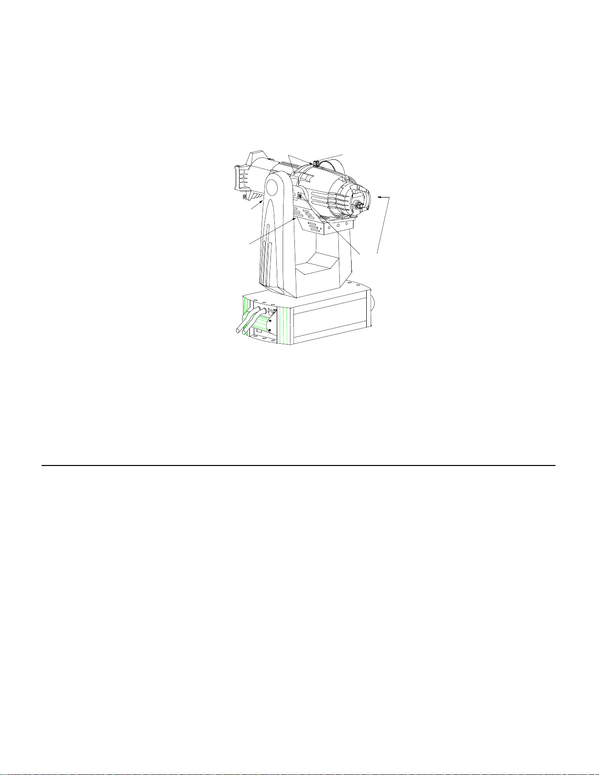
3-7CHANGING LENS TUBES (FOR UNITS WITH AUTOFOCUS)
If the Autoyoke is installed with AutoFocus and you wish to change or replace the Source Four lens tube, follow
these conversion procedures:
REMOVING EXISTING LENSTUBE FROM AUTOYOKE WITH AUTOFOCUS:
·Remove Autofocus cover
·Remove the 1-inch screw holding the front of the lenstube and the autofocus shaft.
·Loosen the 2 jam nuts on the 2-inch screw located just above the focus motor.
·Loosen the 2-inch screw (it is not necessary to remove the screw from the shaft).
·Lens tube may now be removed from the barrel.
MODIFICATION OF THE LENS TUBE:
·Remove plastic knob, ¼" screw and brass ferrule, they are not used. Remove all eight plastic guides,
they are not used.
·Cut strips of "BLACKTAK" 5 ¾" long and cover the slots where the plastic guides were removed in the
previous step. Smoothen "BLACKTAK" carefully to remove creases.
·Disassemble two halves of lens by removing three 8-32 screws with nuts and one 8-32 screw (at the
lower gel clip) which is tapped into the lens tube/ or may be also have a nut in some versions.
·Look at the inside front of the lens. One side of the lens tube has three lens holders and the other side
has two. Lay the side of the lens with the three lens holders down on the bench and carefully separate
the two halves of the lens, leaving the side with the three lens holders on the bench. For European lenses
with the safety screen, keep the screen in the half of the lens with the three lens holders.
·Insert one (1) ¼" x 1/32" flat washer as a shim under the nut opposite the gel frame retaining clip in the
lens casting.
·Put the two halves of the lens back together again. Be careful that the spring clip goes into the hole
properly.
·Reinstall the two 8-32 screws with nylock nuts at the rear of the lens to hold the two lens halves togeth
er. Reinstall one 8-32 screw with nylock nut near the spring clip (use needle-nose pliers or modified nut-
driver to hold the nut)
·Install Front Lens Mount Bracket at the lower gel clip with the one screw which is tapped into the casting.
The clip goes adjacent to the clearance hole. Use the same screw which was in there originally.
-13 -

3-8SECURING THE COUNTERWEIGHT SYSTEM
1.This step must be done after attaching the scroller and DMX Iris to ensure proper balance.
2.Facing the back of the lighting fixture, line up the holes on the bottom of the counterweight halo with
the matching holes on the rear of the connector box. Use two of the counterweight screws (1/4 - 20
x 3/4” socket head cap screws) to secure the counterweight halo into place.
3.The 10 counterweight rings provided with the AutoYoke should be added one at a time until the lighting
fixture is in balance. Facing the back of the lighting fixture, position the Leadrings on the back of the
counterweight halo, lining up the holes. Add Lead weights until the AutoYoke is close to the point of
balance and then add a Steel ring last to sandwich the lead weights. Use the remaining two counter
weight screws (1/4-20 x 2” socket head screws) to secure the rings into place.
***Note: If you are operating the AutoYoke with a Chroma Q scroller you may not need to add the
lead counterweight rings.
TIGHTENALLHARDWARE.
4. The lighting fixture will be in balance when it freely drifts to a horizontal position (perpendicular to the
AutoYoke). Operating the AutoYoke with the lighting fixture out of balance will result in inaccuracy.
***Note: If you are operating the AutoYoke without a scroller or with the lens tube of the lighting
fixture run all the way in, you may not need to add the counterweight rings or the counterweight
halo. In addition, the counterweight quantity may have to be adjusted once the lens tube position is
established. Operating the AutoYoke without a scroller will create an out of balance condition that
will not effect the accuracy or repeatability of the AutoYoke. Though not critical, this out of balance
condition can be improved with the addition of a color extender. Remember to safety all gel slot
accessories.
-14 -

3-9HANGING THE AUTOYOKE
The AutoYoke must be securely attached to the hanging position with hanging clamps. The Power Supply must be
placed either directly above or directly below the lighting fixture for proper operation. A secondary means of
suspension - a safety cable - must be used to prevent the AutoYoke from falling in the event of hanging clamp
failure.
Pan direction is CLOCKWISE from 0% to 100% when the AutoYoke is hanging Power Supply up, facing the Front
Panel, looking at the AutoYoke hanging from below. Keep this in mind when choosing hanging
orientation for optimal travel.
1.Attach hanging clamps to the specified holes on the top of the
Power Supply.
2. Hang the AutoYoke on a minimum of 2’3” centers and with a clearance
of 3’ from the top of the Power Supply to a fully extended lens tube
and scroller.
3.Fasten a safety cable through one of the handles of the AutoYoke, and
secure it to the hanging position.
3-10POWER CABLE
AutoYoke:The cable with the three pin Edison connector supplies power to the AutoYoke. Plug to a
NON DIMpower supply that is configured for a switchable PSUor a hot circuit that does
not pass through a dimmer rack.
Lamp:The cable with the three pin stage or twist lock connector (or without connector) supplies
power to the lighting fixture. Plug it to a dimmer.
3-11DATACABLE
Plug a DMXcable to the male 5-pin XLR on the AutoYoke Power Supply.
· Cable must be twisted pair, 120Ω, shielded EIA485 cable (Belden 9829, 9842 or equivalent),
minimum 22 AWG.
· Recommended maximum cable length is 1640’ (500m). [Recommended Practice for DMX512,
Adam Bennette 1994] Maximum cable length is 2000’ (610m).
· A maximum of 32 DMX receiving devices can be present on a single DMX line.
· The last DMX device on the line must be terminated with a resistor with a value of 120Ω.
-15 -
Hook Clamps

SECTION 4: USER INTERFACE
4-1MENU SYSTEM
Several of the routines (marked with a * below) that are performed at the front panel are also
accessible from the control channel (See Section 5-4, Control Channel, for further operation).
The menu on the front panel of the AutoYoke allows you to do the following:
· Set DMX address
· Calibrate*
· Invert Pan, Tilt, Iris and Focus travel direction
· Select 8- or 16-bit operation
· Select DMX smoothing value
· Set Pan, Tilt, Iris and Focus Limits*
· Display software version
· Invert display
· Change LED display properties
· Restore Factory Defaults
· Display Error messages
Throughout this manual, the following conventions will be used to explain menu navigation:
· Menu:The Menubutton allows you to enter the menu item or return to the
upper level menu items.
· Enter: The Enterbutton allows you to select a function.
· st: The arrow keys allow you to navigate into and out of the
menu system.
· AddrAddr:Menu items that appears on the LED display on the front
panel will be presented in this format.
-16-

4-2AddrAddr- ADDRESS
The AutoYoke requires 7 channels (16-bit) or 5 channels (8-bit) per fixture to operate. The scroller
requires an address other than those addresses occupied by the AutoYoke. When using a Wybron CXI
scroller, the scroller must be addressed at 001001, and it will occupy 3 control channels - the 8th, 9th, and
10th in the sequence when operating in 16-bit and the 6th, 7th, and 8th when operating in 8-bit. When
using a Coloram II scroller, the address at the head (rotary switch) is inconsequential, but the scroller will
always occupythe 8th channel in the sequence (in 16-bit) and the 6th channel in the sequence (in 8-bit).
All other specified scrollers can be set at a user selected DMX address as long as it is not occupied by an
AutoYoke attribute. It is only necessary to select the first DMX address for the AutoYoke.
*NOTE:WHEN USING COLORAM II SCROLLERS, SET THE DIP SWITCHES AS FOLLOWS:
Switch 1 - OFF (Motor Speed - Normal)
Switch 2 - ON (Operation - 24-Chan)
Switch 3 - OFF (Chan Range - 1~12)
Switch 4 - OFF (Fan Speed - Remote Xtrol)
DMX CHANNEL ASSIGNMENTS
16-bit8-bit
1 - Pan Course 1 - Pan
2 - Pan Fine 2 - Tilt
3 - Tilt Course 3 - Iris(occupied if not used)
4 - Tilt Fine 4 - Focus (occupied if not used)
5 - Iris(occupied if not used)5 - Control Channel
6 - Focus(occupied if not used)**Address scroller independently
7 - Control Channel
**Address scroller independently
1.Turn on the AutoYoke. Pan, Tilt, Iris and Focus will AutoCalibrate as the word GoGotravels across the
LED display (This will only occur if the AutoYoke is still configured with Factory Defaults. See Section
4-9 for Factory Default settings). If the AutoYoke is receiving DMX, it will travel to the DMX values
once it has calibrated. If the AutoYoke is not receiving DMX, it will move to a 50/50 position on
the Pan and Tilt axes upon the completion of calibration. The 50/50 position is at the halfway
point of the attributes' travel range. See Section 5-2 for further information about the 50/50 position
.***Note: If the AutoYoke is not receiving DMX, a series of dashes will continuously travel across the
LED display
***Note: The scroller is not part of the AutoCalibrate or Calibrate routine, but will autodetect and
self - test at Power Up.
2.Press Menu:AddrAddr(Address)AddrAddrwill appear on the display.
-17-

3.Press Enter:Default (or previously programmed)
address will appear on the
display.
4. Press st:0 - 5040 - 504Select DMX address from 0 -0 -
504504.
5.Press Enter:Address is recorded.
4-3CALCAL-CALIBRATE
Calibration is necessary to insure accurate operation at both power up and following an error
state. In the event that an AutoYoke is forced off of its recorded position, it should be recalibrated. See
Section 5-6, Encoders, for further information about recovering recorded position after the AutoYoke has
been hit. If the AutoYoke is not Calibrated at power up, it will not operate.
In the Calibrate sub-menu, the options are as follows:
· ALLALLCalibrate Pan, Tilt, Iris and Focus
· CALPCALPCalibrate Pan and Tilt (Tilt always Calibrates with Pan)
· CALtCALtCalibrate Tilt
· CALICALICalibrate Iris
· CALFCALFCalibrate Focus
· ACPACPAutoCalibrate Pan and Tilt at power up
· ACtACtAutoCalibrate Tilt at power up
· ACIACIAutoCalibrate Iris at power up
· ACFACFAutoCalibrate Focus at power up
· The default Calibrate setting is AutoCalibrate Pan, Tilt, Iris and Focus at power up. You may
choose to turn off the AutoCalibrate option or you may choose to AutoCalibrate only some of the
attributes. However, every attribute MUSTbe Calibrated before you operate the AutoYoke. See
Section 5-3, Factory Defaults, for further information.
4-3aCALIBRATE ALL (Pan, Tilt, Iris and Focus):
1.Press Menu:AddrAddr(Address)AddrAddrwill appear on the display.
2.Press st:CALCAL(Calibrate)Advance to CALCAL.
3.Press Enter:ALLALLALLALLwill appear on the display.
4.Press Enter:Pan, Tilt, Iris and Focus will
Calibrate.
-18-
Other manuals for AUTOYOKE
2
Table of contents


