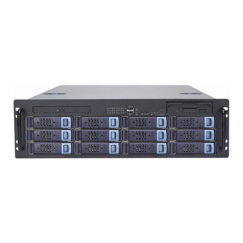
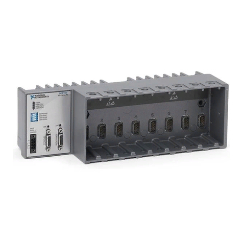
Clavister SC6300 Series Assembly instructions

Installation and Setup guide
ATCA SC6300 Series Chassis
Clavister AB
Sjögatan 6J
SE-89160 Örnsköldsvik
SWEDEN
Phone: +46-660-299200
Fax: +46-660-12250
www.clavister.com
Published 2010-01-27

Installation and Setup guide
ATCA SC6300 Series Chassis
Published 2010-01-27
Copyright Notice
This publication, including all photographs, illustrations and software, is protected under
international copyright laws, with all rights reserved. Neither this manual, nor any of the material
contained herein, may be reproduced without the written consent of Clavister.
Disclaimer
The information in this document is subject to change without notice. Clavister makes no
representations or warranties with respect to the contents hereof and specifically disclaims any
implied warranties of merchantability or fitness for a particular purpose. Clavister reserves the
right to revise this publication and to make changes from time to time in the content hereof
without any obligation to notify any person or parties of such revision or changes.
Limitations of Liability
UNDER NO CIRCUMSTANCES SHALL CLAVISTER OR ITS SUPPLIERS BE LIABLE FOR DAMAGES OF
ANY CHARACTER (E.G. DAMAGES FOR LOSS OF PROFIT, SOFTWARE RESTORATION, WORK
STOPPAGE, LOSS OF SAVED DATA OR ANY OTHER COMMERCIAL DAMAGES OR LOSSES)
RESULTING FROM THE APPLICATION OR IMPROPER USE OF THE CLAVISTER PRODUCT OR
FAILURE OF THE PRODUCT, EVEN IF CLAVISTER IS INFORMED OF THE POSSIBILITY OF SUCH
DAMAGES. FURTHERMORE, CLAVISTER WILL NOT BE LIABLE FOR THIRD-PARTY CLAIMS AGAINST
CUSTOMER FOR LOSSES OR DAMAGES. CLAVISTER WILL IN NO EVENT BE LIABLE FOR ANY
DAMAGES IN EXCESS OF THE AMOUNT CLAVISTER RECEIVED FROM THE END-USER FOR THE
PRODUCT.
2

Table of Contents
Preface................................................................................................................ 5
1.InstallationOverview ......................................................................................... 6
2.Unpacking ........................................................................................................ 8
3.SitePreparation ...............................................................................................10
4.RackMounting .................................................................................................11
5.FrontBladeInstallation ......................................................................................13
6.SF6090SwitchFabricBladeInstallation ................................................................15
7.ConnectingPower ............................................................................................26
8.ThePowerEnclosure .........................................................................................29
3

List of Figures
1.1.TheATCASC6300SeriesChassis ........................................................................ 6
4.1.BladeEjectorLatchOpenPosition ....................................................................12
5.1.BladeEjectorLatchClosedPosition ...................................................................14
6.1.TheSF6090SwitchFabricBlade ........................................................................15
6.2.CorrectTransceiverInsertion............................................................................17
6.3.CorrectXFPInsertion ......................................................................................18
6.4.CorrectSFPInsertion ......................................................................................18
6.5.SFBLatchOpenPosition .................................................................................19
6.6.SFBLatchClosedPosition ................................................................................19
6.7.SFBSerialandEthernetPorts ...........................................................................21
8.1.TheSC6300SeriesChassis1UPowerEnclosure ...................................................29
8.2. Power Rack Rear View - DC Cable Connector Detail .............................................. 31
8.3.DCCablestoPEMConnection ..........................................................................32
8.4.ChassisonPowerRack-FrontView ...................................................................32
8.5.ChassisonPowerRack-RearView ....................................................................33
4

Preface
Target Audience
The target audience for this guide is the user who has taken delivery of a packaged Clavister
SC6300 Series Chassis and going through the installation phase. The guide takes the user from
unpacking and installation to power-up and initial network connection.
Notes to the Main Text
Special sections of text which the reader should pay special attention to are indicated by icons
on the left hand side of the page followed by a short paragraph in italicized text. There are the
following types of such sections:
Note
This indicates some piece of information that is an addition to the preceding text. It may
concern something that is being emphasised or something that is not obvious or
explicitly stated in the preceding text.
Tip
This indicates a piece of non-critical information that is useful to know in certain
situations but is not essential reading.
Caution
This indicates where the reader should be careful with their actions as an undesirable
situation may result if care is not exercised.
Important
This is an essential point that the reader should read and understand.
Warning
This is essential reading for the user as they should be aware that a serious situation
may result if certain actions are taken or not taken.
5

Chapter 1: Installation Overview
The ATCA SC6300 Series Chassis is a high performing, modular, chassis based computing
platform designed for the unique requirements of performance critical environments such as the
telecom industry, service providers, the financial sector and data centers. This manual discusses
chassis installation as well as installation of the SF6090 Switch Fabric Blade. Depending on the
application, different comuputational blades can be inserted into the chassis and these are
covered in separate product manuals.
Figure 1.1. The ATCA SC6300 Series Chassis
Planning for Cabling
The implementation of the cable routing that connects the system to other equipment and
power sources should be planned in advance.
The cables do not need to be available when you first install the product, but you should know
how the cables will be routed and whether they will be connected to the front or the rear of the
chassis. The choice of modules determines where connectors are located.
Follow Electrostatic Discharge (ESD) Precautions
Components can be damaged by electrostatic discharge (ESD). When an installation step
instructs you to protect any replaceable component from ESD, follow the precautions described
6

below:
• Products contains static-sensitive components and should be handled with care. Failure to
employ adequate anti-static measures can cause irreparable damage to components.
• Handle the product only when wearing a grounded wrist strap at a grounded work area.
• Don't remove blades from the chassis or from their electrostatic discharge (ESD) shielding
bags until a step instructs you to do so. Failure to follow ESD precautions may damage
components.
Chapter 1: Installation Overview
7

Chapter 2: Unpacking
The following steps should be followed to unpack the SC6300 Series Chassis:
1. Use either an ESD wrist strap, or ESD heel straps on a conductive floor surface, as you open
the packaging.
2. Remove the SC6300 Series Chassis from its packaging and place it so the slots are oriented
horizontally and right side up.
The chassis houses the bladess that make up the total system. The chassis also provides
power and thermal management to the blades and supports the product's chassis
management architecture.
3. Verify that you have the following components, either shipped with the chassis or delivered
separately
•1 x Air filter.
•2 x Fan Trays.
•2 x Power Entry Modules (PEMs).
•1 x ESD wrist strap.
•1 x Front cable guide (option).
The power-feed and ground cables are required, but not supplied, since they are specific to
the site or to the configuration.
4. Verify any additional ordered components are in the shipment. These can include:
• Standard configurations include one or two SF6090 Switch Fabric Blades (SFBs). The
SFBs should already be installed in the chassis.
• Rear slots will be completely populated with filler panels, except for those slots where
the included front blades have companion rear transition modules installed.
• System configurations that do not have all the front slots populated must have active
blades or air management filler panels installed in them to maintain system airflow.
Additional air management filler panels can be ordered separately.
5. Perform a thorough inspection of the entire system to confirm components are properly
installed, seated, and not loose. Pins, shrouds, mounting screws, and other items can
become loose or damaged during the course of handling, shipping, and assembly.
Operating a damaged system can harm the chassis and the devices that interface to it.
8

Warning
Operating damaged equipment can harm the chassis and the devices that interface
with it.
Chapter 2: Unpacking
9

Chapter 3: Site Preparation
It should be verified that the installation site meets the following requirements:
1. Access to the installation site and the equipment should be restricted to authorized
personnel only.
2. A readily accessible disconnect device must be incorporated into the building's wiring
between the chassis Power Entry Module (PEM) input terminals and the power source.
3. The required rating of the disconnect device is determined by the nominal input voltage.
See the table below for a list of permitted nominal inputs and the corresponding disconnect
device ratings.
Nominal Input Disconnect Device Ratings
-48 V 60 VDC @ 40 A
-60 V 80 VDC @ 40 A
4. The SC6300 Series Chassis requires at least 5 centimetres (2 inches) of unobstructed
clearance at the side air inlets and outlets to ensure sufficient airflow for the individual
blades.
5. The installation site must be compatible with the recommended temperatures:
• The SC6300 Series Chassis has a maximum recommended continuous operating
temperature of 40°C.
• The chassis is rated to operate during transient conditions from -5° to 55°C for a
maximum of 96 consecutive hours.
• In closed or multi-rack assembly environments, the local ambient temperature may be
greater than the room ambient.
10

Chapter 4: Rack Mounting
The SC6300 Series Chassis can be placed on a flat surface, such as a table, or mounted in a rack.
For mounting in a rack, there are two stages:
A. Rack preparation.
B. Chassis installation.
A. Rack Preparation
The rack needs to be checked for the following:
1. Verify that the rack environment in which the equipment is to be installed is compatible
with the maximum transient operating temperature (55°C).
2. Confirm the rack is stable and will not tip over when the chassis is being loaded in it.
3. Verify that the rack has support rails installed. Refer to the rack's documentation for
information on installing the rack and the required rails .
Warning
Do not attempt to install the chassis if rails are absent or if the rack's ears are the only
support for the chassis weight. THE CHASSIS FRONT MOUNTING BRACKETS ARE NOT
INTENDED TO SUPPORT THE WEIGHT OF THE CHASSIS AND ITS BLADES.
B. Install the Chassis
To install the chassis in the rack, the steps are as follows:
1. If the chassis is to be lifted by hand into the rack, it is recommended that all the blades from
the front of the chassis are removed to reduce weight.
If you are using equipment to lift the chassis into the rack then the removal of blades can
you should go directly to step 2.
• Loosen the thumb screws on each blade and lift the ejector latches to the open position.
11

Figure 4.1. Blade Ejector Latch Open Position
• Remove and place each blade in a separate anti-static bag or on a grounded surface. Do
not stack the blades on top of each other. When handling the blades, follow the ESD
precautions described above.
Employ at least two people and use safe lifting precautions to lift the chassis into the rack
and slide it onto the support rails.
2. Secure the chassis to the rack by its mounting brackets. Refer to the rack's documentation
for information on the appropriate hardware to use.
3. Verify that the chassis is level and not twisted in the rack. Uneven mounting may cause
difficulties with blade installation and alignment of chassis features.
Chapter 4: Rack Mounting
12

Chapter 5: Front Blade Installation
This section dicusses the general installation steps for the front blades in the SC6300 Series
Chassis. A detailed description for the installation of SFBs can be found in Chapter 6, SF6090
Switch Fabric Blade Installation. A detailed description for how to install different processor blades
can be found in the separate manuals for each blade type.
Modules should be inserted into the SC6300 chassis in the following order:
1. The first SFB should be first fitted into slot 2 using the steps described below.
2. A second SFB goes into slot 1. If there is only one SFB, install an air management filler panel
into slot 1.
3. Install the processing blades and any other front-slot blades, one at a time, using the same
steps described below. Follow any specific slot-assignment instructions, otherwise, use the
slots closest to the SFBs.
The general steps for installing any blade into the chassis are as follows:
1. Attach your ESD wrist strap to one of the front ESD friction-lock connectors, which are
located in the top corners of the chassis. Protect the blades from ESD damage as described
previously.
2. Slide the blade half way into the physical slot.
If correctly aligned, the right and the left edges of the blade will fit within the narrow
channels of the chassis.
3. To fully seat a blade into the chassis:
• Lift the ejector latches outward to the open position, and insert the blade all the way
into the chassis.
• Close both ejector latches simultaneously. This will seat the blade's connectors into the
backplane.
13

Figure 5.1. Blade Ejector Latch Closed Position
4. If a blade mates with a rear transition module, confirm that the rear transition module's zone
3 connection is located at the rear of the slot before installing the blade.
5. Install front and rear air management filler panels into any empty slots:
• Do NOT use blank faceplates in place of filler panels. To ensure proper thermal and
emission profiles, use flow blocking filler panels.
• Load the node slots with active blades sequentially from bottom to top and install flow
blocking filler panels in all unpopulated slots.
Chapter 5: Front Blade Installation
14

Chapter 6: SF6090 Switch Fabric Blade
Installation
Prerequisites
This section describes the specific installation of the SF6090 Switch Fabric Blade (SFB) into the
SC6300 Series Chassis. Correct installation will require the following:
•A 9-pin D-shell to RJ-45 serial port cable (shipped with the SFB).
•A standard Ethernet crossover cable.
•Adequate ventilation for all hardware.
15

Figure 6.1. The SF6090 Switch Fabric Blade
Important ESD Precautions
Electrostatic discharge can cause permanent damage to static-sensitive components in this
product. Important ESD procedures include:
• Keep the product in its ESD shielding bag until a step tells you to remove it.
• Put on a grounded wrist strap before you move near or touch the product.
• Install the product only in a grounded work area.
Installing SFPs or XFPs
The SFB comes with sockets for small form-factor pluggable (SFP) and 10 Gigabit small
form-factor pluggable (XFP) transceiver modules. If SFPs and XFPs are installed, they can provide
external connections to the Ethernet interfaces. The sockets are accessed from the faceplate of
the SFB.
Configuration recommendations
Standard SFB configurations come without SFP or XFP transceivers installed. To protect the
internal components of the SFB, transceivers or filler plugs must be installed in all empty sockets:
• The Base Ethernet configuration supports up to four SFP transceivers and one XFP
transceiver, with filler plugs installed in unused sockets.
• The Fabric Ethernet configuration supports up to four XFP transceivers, with filler plugs
installed in unused sockets.
A list of tested and qualified transceivers and filler plugs can be supplied by Clavister
Transceiver Installation
SFP and XFP transceivers can be installed on the SFB at any time, but Clavister recommends
performing the installation before the SFB is installed in the chassis.
Chapter 6: SF6090 Switch Fabric Blade
Installation
16

Figure 6.2. Correct Transceiver Insertion
The illustration above shows the correct orientation for inserting SFP transceivers. The SFP you
use may vary in appearance depending on manufacturer, but the same insertion guidelines,
listed below, should be followed. Use the same guidelines when inserting XFP transceivers as
well.
1. Follow ESD precautions and make sure you are adequately grounded.
2. Remove the transceivers and the SFB from their antistatic bags.
3. On the SFB's faceplate, remove the filler plugs from the sockets in which you are installing
the SFP or the XFP transceivers. For sockets not being used, keep the filler plugs in place to
protect the internal components of the board.
4. Make sure the transceiver's bale (the latch on the cable side of the transceiver) is in the
closed position. This will ensure the transceiver snaps into position when inserted into the
socket.
5. How you insert the transceiver into the socket depends on the SFB's orientation:
• If the SFB is oriented vertically, insert the transceiver so the connector side is on the left.
• If the SFB is oriented horizontally, insert the transceiver so the connector side is down.
6. Once inserted into the socket, carefully slide the transceiver until its connector is fully seated
and snaps into position.
7. Repeat the above steps for each transceiver being installed.
8. For transceivers with cable plugs installed on their cable side, keep the plugs in place until
you are ready to plug cables into the transceivers. The cable plugs protect the internal
components of the transceivers.
Chapter 6: SF6090 Switch Fabric Blade
Installation
17

Filler Plug Installation
If XFP or SFP transceivers are removed, install either replacement transceivers or filler plugs in the
sockets to protect the internal components of the SFB.
Additional filler plugs can be ordered from the applicable manufacturer. For a list of tested and
qualified transceivers and filler plugs, contact Clavister.
Install fillers plugs using the insertion guidelines described below:
A. XFP Filler Plug Installation
• If the SFB is oriented vertically, insert the filler plug so the recessed side is on the left and the
flat, smooth side is on the right.
• If the SFB is oriented horizontally, insert the filler plug so the recessed side is on the bottom
and the flat, smooth side is on the top.
Figure 6.3. Correct XFP Insertion
B. SFP Filler Plug Installation
• If the SFB is oriented vertically, insert the filler plug so the connector side and retaining clip
are on the left.
• If the SFB is oriented horizontally, insert the filler plug so the connector side and retaining clip
are on the bottom.
Figure 6.4. Correct SFP Insertion
Chassis Installation
Chapter 6: SF6090 Switch Fabric Blade
Installation
18

This section assumes that you are installing the SFB in a Clavister chassis and the chassis power is
on. The Clavister chassis architecture allows insertion and removal of blades without powering
down the system. The SFB powers up all other blades within the chassis.
The steps for installation are:
1. Follow ESD precautions and make sure you are adequately grounded before handling the
transceivers and the SFB.
2. Remove the SFB from its antistatic bag.
3. Open both ejector latches outward.
Figure 6.5. SFB Latch Open Position
4. Slide the SFB into one of the hub slots on the chassis. The hub slots for the SC6300 Series
Chassis are numbers 1 and 2.
If correctly aligned, the edges of the SFB will fit within the narrow guide rails of the chassis.
Warning
Do not force the SFB into the slot:
a. To avoid damage to connectors, make sure the rear slot is either empty or
contains a module that is compatible with the SFB.
b. If the SFB does not slide in easily, make sure that it is being inserted it into the
correct slot and that it is aligned properly.
5. Once the SFB is inserted all the way into the chassis, simultaneously close both ejector
latches inward. This will seat the SFBs connectors into the chassis backplane.
Figure 6.6. SFB Latch Closed Position
The hot-swap (H/S) LED light flashes until the SFB is fully powered up. Once powered up, the
LED light will turn off.
If the LED remains solid blue or keeps flashing after the SFB is inserted, it indicates the
Chapter 6: SF6090 Switch Fabric Blade
Installation
19

installation has failed.
6. Secure the SFB in its slot by hand tightening the two fastening screws on each end of the
blade's front panel.
7. Repeat these steps if you are installing a second SFB in the remaining hub slot. Installing two
SFBs on the chassis allows for redundancy which is a means of providing continuous system
functionality even if a failure occurs on one of the SFBs.
Connecting to an External Computer and Network
The SFB can be accessed by an external computer through the serial and the Ethernet
maintenance ports. Use the serial port to perform diagnostic and verification procedures. Use the
Ethernet maintenance port to connect the SFB to the network and to perform configuration
procedures.
Note
If two SFBs are installed, connect to each one separately.
Connecting to the Serial Port
1. Connect the included serial port cable by plugging one end into the RJ-45 serial port
labeled LMP SER on the SFB (see illustration Figure 6.7, “SFB Serial and Ethernet Ports”
below).
2. Connect the cable's other end to the COM1 or the COM2 serial port of an external computer,
such as a laptop.
3. Start a terminal-emulator application, such as Procomm Plus® or minicom, on your
computer or laptop. The connection parameters are:
• Speed 115200 baud.
• 8 data bits
• No parity
• One stop bit
• No hardware or software flow control.
4. Press the Enter key and verify you get a login prompt.
5. Enter the command:
admin
6. Verify that you receive a welcome message and the prompt:
ATCA-2210#
Chapter 6: SF6090 Switch Fabric Blade
Installation
20
Table of contents
