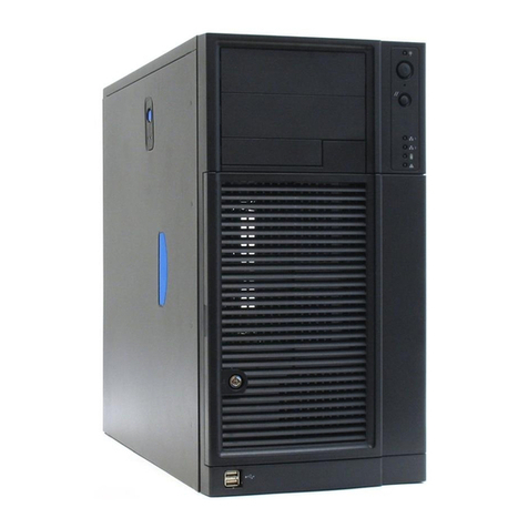
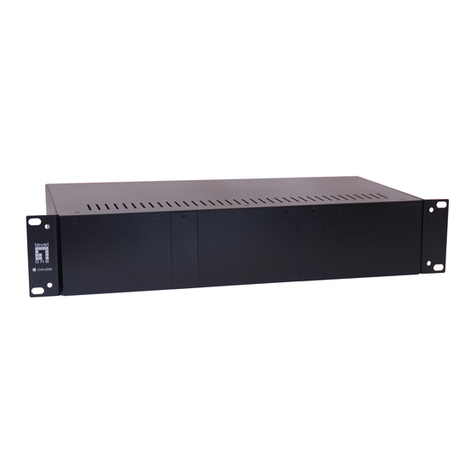
Merging Quintessence User manual


ii Quintessence User Manual © 2007 Merging Technologies
Doc Version: 1.32 (September 2007) © 2007 Merging Technologies

© 2007 Merging Technologies Quintessence User Manual iii
No part of this documentation may reproduced in any form whatsoever or be stored in any
data retrieval system without prior written permission of the copyright owners.
This documentation is supplied on an as-is basis. Information contained within this
documentation is subject to change at any time without notice and must not be relied upon.
All company and product names are ™ or Registered Trademarks ® of their respective
owners. Windows XP, Windows 2000 and Windows NT are trademarks of Microsoft
Corporation.
Merging Technologies makes no warranties express or implied regarding this software, its
quality, performance, merchantability or fitness for a particular purpose. The software is
supplied “as is” you, the purchaser, are assuming the entire risk of the results of using this
Merging Technologies software.
In no circumstances will Merging Technologies, its owners, directors, officers, employees or
agents be liable to you for any consequential, incidental or indirect loss or damages including
loss of time, loss of business, loss of profits, loss of data or similar resulting from the use of
or inability to use the Merging Technologies hardware and or software or for any defect in the
hardware software or documentation.
© Copyright Merging Technologies Inc. 2007. All rights reserved.

iv Quintessence User Manual © 2007 Merging Technologies
Table of Contents
IMPORTANT NOTICE: ..................................................................................................................................VI
STATIC DANGER NOTICE:........................................................................................................................ VI
PRODUCT REGULATORY COMPLIANCE..................................................................................................VI
PRODUCT SAFETY COMPLIANCE..................................................................................................................... VI
PRODUCT EMC COMPLIANCE ........................................................................................................................ VI
ELECTROMAGNETIC COMPATIBILITY NOTICES ................................................................................................. VI
ENVIRONMENTAL LIMITS ..........................................................................................................................VII
SYSTEM OFFICE ENVIRONMENT .....................................................................................................................VII
CONTACTING MERGING ...........................................................................................................................VIII
1 – INTRODUCTION.......................................................................................................................................9
THANK YOU! ................................................................................................................................................... 9
Creativity Distilled...................................................................................................................................... 9
2 - INSTALLATION.......................................................................................................................................10
POSITIONING ................................................................................................................................................ 10
Merging Quintessence AV Case Temperature Measurements .............................................................. 10
MAKING CONNECTIONS................................................................................................................................. 10
3 – EXTERNAL FEATURES.........................................................................................................................11
FRONT PANEL .............................................................................................................................................. 11
Power and Reset..................................................................................................................................... 11
USB/FireWire........................................................................................................................................... 11
REAR PANEL ................................................................................................................................................ 12
Connections............................................................................................................................................. 12
Quintessence Serial Number .................................................................................................................. 12
4 – CHASSIS MODULES..............................................................................................................................13
Overview.................................................................................................................................................. 13
MTCHIO SYNC BOARD ................................................................................................................................13
INTERNAL CONNECTIONS &JUMPERS ............................................................................................................ 13
Mykerinos Connection............................................................................................................................. 14
Jumpers and Power ................................................................................................................................ 14
RS-232 connection.................................................................................................................................. 15
USB to RS-232 adapter........................................................................................................................... 16
MTCHIO PANEL CONNECTIONS.................................................................................................................... 18
FRONT PANEL USB /IEE 1394A MODULE .................................................................................................... 20
FRONT PANEL LOGO MODULE ....................................................................................................................... 21
5 – STORAGE...............................................................................................................................................22
HARD DISK /CD-ROM TRAYS ...................................................................................................................... 22

© 2007 Merging Technologies Quintessence User Manual v
Hard Disk Tray......................................................................................................................................... 22
CD / DVD / Removable Media Drives ..................................................................................................... 22
ADDING STORAGE ........................................................................................................................................ 23
6 – CARD RETENTION ................................................................................................................................24
7 – SAMPLE SYSTEM SPECIFICATIONS ..................................................................................................25
PYRAMIX &VCUBE SYSTEMS ....................................................................................................................... 25
LUXOR &VCUBE HD2K SYSTEMS................................................................................................................ 25
8 – DIMENSIONS..........................................................................................................................................26
Pyramix & VCube weights & dimensions ................................................................................................ 26
Luxor & VCube HD2K weights & dimensions .........................................................................................26
9 – TROUBLESHOOTING............................................................................................................................27
APPENDIX I ..................................................................................................................................................28
MOTHERBOARD SPECIFIC NOTES .................................................................................................................. 28
RS-232 .................................................................................................................................................... 28
Tyan Thunder S2676 motherboard only ................................................................................................. 28
APPENDIX II .................................................................................................................................................29
LUXOR AND VCUBE HD2K SLOT CONFIGURATION......................................................................................... 29
Luxor........................................................................................................................................................ 29
VCube HD2K ........................................................................................................................................... 29

vi Quintessence User Manual © 2007 Merging Technologies
IMPORTANT NOTICE:
Please read the following information very carefully before attempting any installation. Failure to comply
with the precise instructions may result in damage to your Merging hardware. Please read this entire
section of the manual carefully before installation.
STATIC DANGER NOTICE:
Please note that the Quintessence AV Chassis contains delicate electronic components that can be
damaged or even destroyed when exposed to static electricity. Take all necessary precautions not to
discharge static electricity when touching any of the AV Case connectors.
Product Regulatory Compliance
The Merging Pyramix, VCube and Luxor Chassis are designed and tested to meet the standards and
regulations listed in the following sections when configured with the workstation/server boards specified.
Product Safety Compliance
The Merging Chassis complies with the following safety requirements:
•UL 1950 – CSA 950 (US/Canada).
•EN 60 950 (European Union).
•IEC 60 950 (International).
•CE – Low Voltage Directive (73/23/EEC) (European Limits).
•EMKO-TSE (74-SEC) 207/94 (Nordics).
Product EMC Compliance
The system has been tested and verified to comply with the following EMC regulations when configured
with the workstation/server boards specified
•FCC (Class A Verification) – Radiated and Conducted Emissions (USA).
•CISPR 22, 3rd Edition (Class A) – Radiated and Conducted Emissions (International).
•EN45022 (Class A) – Radiated and Conducted Emissions (European Union).
•EN45024 (Immunity) (European Union).
•EN6100-3-2 & -3 (Power Harmonics and Fluctuation and Flicker).
•CE – EMC Directive (89/33/EEC) (European Union).
Electromagnetic Compatibility Notices
This device complies with Part 15 of the FCC Rules. Operation is subject to the following two conditions:
(1) this device may not cause harmful interference and (2), this device must accept any interference
received, including interference that may cause undesired operation.
This equipment has been tested and found to comply with the limits for a Class A digital device, pursuant to
Part 15 of the FCC Rules. These limits are designed to provide reasonable protection against harmful
interference in a residential installation. This equipment generates, uses, and can radiate radio frequency
energy and, if not installed and used in accordance with the instructions, may cause harmful interference to
radio communications. However, there is no guarantee that interference will not occur in a particular
installation. If this equipment does cause harmful interference to radio or television reception, which can be
determined by turning the equipment off and on, the user is encouraged to try to correct the interference by
one or more of the following measures:
•Reorient or relocate the receiving antenna.
•Increase the separation between the equipment and the receiver.
•Connect the equipment to an outlet on a circuit other than the one to which the receiver is connected.
•Consult the dealer or an experienced radio/TV technician for help.

© 2007 Merging Technologies Quintessence User Manual vii
Any changes or modifications not expressly approved by the grantee of this device could void the user’s
authority to operate the equipment. The customer is responsible for ensuring compliance of the modified
product.
Only peripherals (computer input/output devices, terminals, printers, etc.) that comply with FCC Class B
limits may be attached to this computer product. Operation with noncompliant peripherals is likely to result
in interference to radio and TV reception.
All cables used to connect to peripherals must be shielded and grounded. Operation with cables,
connected to peripherals that are not shielded and grounded, may result in interference to radio and TV
reception.
Environmental Limits
System Office Environment
Parameter Limits
Operating Temperature +5 degrees C to +35 degrees C with the maximum rate of change not to exceed 10
degrees C per hour.
Non-Operating Temperature -40 degrees C to +70 degrees C
Non-Operating Humidity 95%, non-condensing @ 30 degrees C
Acoustic noise less than 40 dBA in a typical office ambient temperature (18-25 degrees C)
Operating Shock No errors with a half sine wave shock of 2G (with 11-millisecond duration).
Package Shock Operational after a free fall, 18 – 24 inch depending on the weight.
ESD 15kV per Merging Environmental Test Specification

viii Quintessence User Manual © 2007 Merging Technologies
Quintessence Warranty Information
This product is warranted to be free of defects in materials and workmanship for a period of one year from
the date of purchase. Merging Technologies, Inc. extends this Limited Warranty to the original purchaser.
In the event of a defect or failure to confirm to this Limited warranty, Merging Technologies, Inc. will repair
or replace the product without charge within sixty (60) days. In order to make a claim under this limited
warranty, the purchaser must notify Merging Technologies, Inc. or their representative in writing, of the
product failure. In this limited warranty the customer must upon Merging Technologies, Inc. request, return
the product to the place of purchase, or other local designation, for the necessary repairs to be performed.
If the consumer is not satisfied with the repair, Merging Technologies, Inc. will have the option to either
attempt a further repair, or refund the purchase price.
This warranty does not cover: (1) Products which have been subject to misuse, abuse, accident, physical
damage, neglect, exposure to fire, water or excessive changes in the climate or temperature, or operation
outside maximum rating. (2) Products on which warranty stickers or product serial numbers have been
removed, altered or rendered illegible. (3) The cost of installations, removal or reinstallation. (4) Damages
caused to any other products.
Contacting Merging
International Office:
Merging Technologies S.A.
Le Verney
CH-1070 Puidoux
Switzerland
Phone: +41 21 946 0444
Fax: +41 21 946 0445
USA:
Merging USA (Independent Audio)
43 Deerfield Road
Portland,
ME 04101-1805
United States of America
Phone: +1 (207) 773 2424
Fax: +1 (207) 773 2422
For all documentation inquiries or suggestions for improvement:
www.merging.com

© 2007 Merging Technologies Quintessence User Manual 9
1 – Introduction
Thank you!
Congratulations on your Merging Technologies Quintessence AV Chassis purchase. Quintessence is a
precision enclosure with custom interface modules for Pyramix and VCube workstations and the Luxor
Media Server and will considerably enhance the operating experience.
Creativity Distilled
Quintessence is a custom designed aluminium Chassis, with a very efficient, low-noise cooling system and
bespoke interface modules. From first acquaintance, this engineering masterpiece induces a sense of
confidence and calm, highly conducive to creativity. The softly glowing blue Pyramid of the power switch
echoes the sculpted front panel, subtle reminders of an earlier civilization’s creative expertise.
Quintessence embodies the features you should expect from a machine designed for exacting professional
environments. Cooling is efficient and quiet and there is ample space for extra hardware. Drive bays are
suspended and shock mounted. The recessed rear panel hosts a comprehensive set of studio grade
connections.

10 Quintessence User Manual © 2007 Merging Technologies
2 - Installation
Positioning
Rack spacing and airflow recommendations:
When Quintessence is to be rack-mounted, we recommend allowing one RU of blank space below the unit,
in order to allow for optimum air flow to cool the equipment.
However, in the following specific circumstances the bottom air intake can be obstructed and machines
may be stacked without the recommended blank space:
1. Machine room or rack ambient temperature is kept below 25°
2. Side air intake is kept completely free of obstacles (rack mounting rails, cables, etc.) and ample airflow
is available in the left side of the rack
3. Rear air exhaust outlets also are kept as unobstructed as possible (tidying the cabling out of the way of
PSU fan and chassis’s fans is a must) and ample air flow is available at the rear of the rack
On the other hand, in the following situations the bottom air intake should be left completely open:
4. When multiple high RPM (SCSI / FC / SATA 10’000rpm or more) hard drives are installed in the
machine
5. When a Dual Xeon machine is used for processing intensive tasks such as HD Video playback and/or
recording
So as rule of thumb, while the bottom air intake of a standard VCube / Pyramix or of a Luxor server with
external storage can, under specific conditions, be obstructed without problem, it is highly recommended
that a VCube HD2k or a Luxor server with internal storage is installed with a blank space below the unit.
In the Table below, differences between open and closed bottom air intakes are displayed in Celsius. The
sensor was placed in the centre of the chassis, immediately behind the internal hard drives.
Warning! If in any doubt when installing, please check that the internal temperature of your
machine remains within the range shown.
Merging Quintessence AV Case Temperature Measurements
Bottom Air Intake
Pyramix / VCube SD Ambient Open Closed Delta
1x SATA 120GB 23 28 34 6
Luxor / VCube HD Ambient Open Closed Delta
6 x SATA250GB 24 29 35 6
Making Connections
Note: Please ensure that the host PC and any powered network switch is switched off
before making connections to the Quintessence AV Case.

© 2007 Merging Technologies Quintessence User Manual 11
3 – External Features
Front Panel
Power and Reset
The elegant blue Merging Logo also houses the Power and Reset buttons. As shown below, the chassis’
Soft Power function is controlled by the left-hand, larger, section of the pyramid while smaller, right-hand
part is used to invoke the Reset function. Reset button illumination increases in intensity to denote hard
drive activity.
The logo glows softly when the machine is in standby. I.e. connected to the mains but in power-off mode.
USB/FireWire
Two flush mounted front-panel USB 2.0 & an IEE1394a Firewire socket provide convenient connections for
dongles, external drives or auxiliary equipment.
POWER & RESET

12 Quintessence User Manual © 2007 Merging Technologies
Rear Panel
Connections
From top to bottom and left to right:
•4 x DB-25 slots for 4 x 8 channels of AES/EBU, SDIF or TDIF I/O installation
•Power Supply with IEC socket, voltage selector and switch
•RS-422 connector with master / slave mode switch, for machine or remote control connections.
•WordClock I/O, Video Reference Input & Video Reference Output on BNC connectors
•TimeCode “SMPTE-EBU” LTC Input and Output on XLR connectors
•PS-2 keyboard and mouse, DB-25 parallel and DB-9 Serial connectors
•Firewire / IEE1394a, Gigabit Ethernet and USB connectors and on-board audio jacks.
•7x “PCI” mounting brackets (one populated with Graphic card)
Note: The precise content and layout will depend on the motherboard and power supply of
the specific model.
Quintessence Serial Number
The Serial number plate is located on the rear of the chassis above the power supply fan grille:

© 2007 Merging Technologies Quintessence User Manual 13
4 – Chassis modules
Overview
The MTCHIO Sync Board module, coupled with the master Mykerinos board, provides various I/O directly
to the rear of PC. The USB/FIREWIRE (IEEE1394) module extends the internal USB and Firewire
connections directly to the front panel of the PC. Finally, the LOGO module extends the motherboard
power switch, reset switch and IDE activity LED to the front panel of the PC.
MTCHIO Sync Board
(Pyramix and VCube Systems only)
(Merging Technologies CHassis Input Output)
MTCHIO stands for Merging Technologies Chassis Input and Output. (We are very fond of this name,
particularly since we discovered that in French MTCHIO pretty much means “love your puppies”. This
custom panel, located on the rear of the Merging chassis, extends the sync I/O capabilities of the
Mykerinos board with user friendly connectivity and adds some interesting new features. It has been
designed to mirror and improve all the connections found on the Mykerinos optional TC-Breakout cable.
Internal Connections & Jumpers
LTC OUT LTC In
J2
see note J6 - Video / TC
to Mykerinos Master
J1 - RS-232
Asus & USB J3 - RS-232
Other
manufacturer
JP1
see note
JP2
see note
JP 4& 5 JP3
see note
RS-422 Switch
Machine (up)
Controller (down)
V
ideo
Ref OUT
WordClock
I/O
V
ideo
Ref IN
RS-422
V
ideo T
Switch

14 Quintessence User Manual © 2007 Merging Technologies
Mykerinos Connection
•J6 – 16 pin ribbon cable to the primary (master) Mykerinos card for TimeCode and sync. In order for
the MTCHIO Sync board’s TimeCode & Video functionalities to be fully operational, it is necessary to
connect the J6 socket to the primary (TimeCode Master) Mykerinos card, with the 16 pin ribbon cable
provided. In multi-board systems, by convention, the primary Mykerinos card is the one fitted in the PCI
slot closest to the graphics adapter. Note: video termination Jumper 4 on the TimeCode Master
Mykerinos should be set to OPEN when used in conjunction with MTCHIO.)
Jumpers and Power
•JP1 – 75Ωtermination for the Word clock input signal
•JP2 – 5V from the PC power supply through the Molex (J2) connector (hard disk type connector)
•JP3 – 5V from the Mykerinos board through the 16 pin ribbon cable connected to the Video/TC
header.
The internal Molex connector J2 is used to provide +12V to the rear fans through JP4 and JP5 terminals. It
also provides alternative +5V to the MTCHIO module through jumper JP2.
WARNING: Never close JP2 and JP3 at the same time.
Power and Fan Connectors
•J2 Molex connector takes power from PC PSU
Detailed pinout of J2:
•JP4 & JP5 provide +12V to the rear panel fans of the chassis. Here is the pinout of JP4 and JP5.
+12V GND
+12V
GND
GND
+5V
JP4 JP5
J2

© 2007 Merging Technologies Quintessence User Manual 15
RS-232 connection
•J1 – RS-232 connector with pinout A works with Asus and Intel on-board RS-232 connectors. This is
also the connector used with the Merging Technologies USB to RS-232 adaptor. (see below)
•J3 – RS-232 connector with pinout B is provided for compatibility with motherboards from other
manufacturers.
Note: This connector may not be available on recent revisions of the MTCHIO board.
If in any doubt, please refer to your motherboard User Manual and ensure the on board connector matches
the pinout of either J1 or J3 as shown here:
RS-232 Socket Pinouts
J1 J3
1 NC 2 RX 1NC 2 NC
3 TX 4 NC 3RX 4 NC
5 GND 6 NC 5TX 6 NC
7 NC 8 NC 7NC 8 NC
9 NC 10 NC 9GND 10 NC

16 Quintessence User Manual © 2007 Merging Technologies
USB to RS-232 adapter
Since many modern motherboards do not have spare RS-232 headers MTCHIO is generally supplied from
the factory already connected to an on-board USB header via an included USB to RS-232 adapter and
cable.
The RS-232 USB converter transforms RS-232 signals to/from USB signals. It has been developed to
allow the MTCHIO RS-422 functionality to be retained with motherboards lacking an internal RS-232
connector. This converter is USB 2.0 compliant (12Mbps).
The RS-232 USB module must be inserted into the J1 connector.
Warning! Due to the small dimensions of the RS-232 connector, it is possible to incorrectly
insert the plug. Please ensure it is correctly aligned as in this picture:

© 2007 Merging Technologies Quintessence User Manual 17
USB to RS-232 adapter Software Installation
Where a USB to RS-232 converter is supplied, a driver is required:
1. Do not plug the 5 pin connector of the Merging Y-type USB cable into a USB port of the motherboard.
First, power on the computer and extract the drivers located on the accompanying CD to a temporary
folder. The file to extract is labelled CP210X_DRIVERS.EXE.
2. Then, plug the 5 pin connector of the Merging Y-type USB cable into a USB connector of the
motherboard. There is no need to power off the computer at this stage!
3. Windows will detect a new USB device and ask for the drivers. Choose the folder in which you have
previously extracted the file and go to the following directory:
4. ...\SiLabs\MCU\CP210x\WIN
5. Continue the installation.
6. Once the drivers are installed, Windows will detect a USB to RS-232 Bridge and ask for the drivers.
Give the same location as in point 3and continue until the installation is complete.
7. If all is well, the blue converter LED should be ON indicating that the USB link is now fully operational.
Check in Windows Device Manager, that you can see a new COM port labelled like this: CP2102 USB
to UART Bridge Controller (COM4). Of course, the COM port number will depend on the number of
COM ports present on your computer.

18 Quintessence User Manual © 2007 Merging Technologies
MTCHIO Panel Connections
WordClock, Video Ref and LTC connections provide identical functionality to that originally offered by the
TC-BreakOut optional cable. RS-442 provides functionality originally enabled by external 3rd party RS-232
to RS-422 adapters such as an “Antona”.
Note: Please take care never to connect an (old) optional breakout cable and a MTCHIO
board to the TC Master Mykerinos at the same time.
RS – 422
This DB-9 socket is an RS422* port for connecting a machine or a controller utilizing the Sony 9-pin (P2)
protocol without having to use an external RS232 to RS422 converter. A switch, labelled to Machine and
from Controller, enables the port to be configured correctly, depending on what it is connected to. This
fully featured RS-422 connection (rather than a modified RS-232) offers direct and hassle free connection
to professional outboard equipment such as video player/recorders, workstations or remote controllers.
to Machine means that Pyramix/VCube will control an external Machine and from Controller means that
Pyramix/VCube will be controlled by an external controller.
When Pyramix/VCube controls a machine, a Machine must be created and the proper COM port**
selected in Pyramix Settings or by activating Sony 9-PIN Machine in VCube Settings. In order to achieve
proper synchronization the correct TC Source must be selected, such as External (with the correct machine
selected as Ext. TC Source), in Pyramix Settings or Ext selected in the VCube Transport Panel. Then
Pyramix/VCube can be put into Chase mode in the Transport Panel.
When Pyramix/VCube is controlled by an external 9-PIN controller, a Controller must be created in
Pyramix Settings or Sony 9-PIN Controller should be checked in VCube Settings.
Note: Remember that a single common timebase for the entire system is essential for trouble free machine
synchronization. A proper Video Reference and possibly WordClock should be distributed to all machines
to enable them to base their TimeCode calculations and derive their digital audio/video clocks from a single
common clock source. Please also see below for more about WordClock & Video Ref.
Note*: the RS-422 adapter is attached to an internal USB2 port via a dedicated USB to RS-232
adapter.
Note**: The COM Port used by RS-422 adapter will most probably be COM2 (COM1 is normally
assigned to the rear panel on-board RS-232 port). But since our RS-422 adapter now is attached to a
USB port, it may happen that Windows decides to get real fancy and decides that COM1, or COM3 !
should be the RS-422 COM Port, depending on hardware configuration.
COM ports can be identified in: My Computer > Properties > Hardware > Device Manager > Ports (Com
& LPT) and identify the following line: CP210x USB to WART Bridge Controller (COMxx). Note the
corresponding COM port listed in between the brackets and change Pyramix/VCube Settings to match.

© 2007 Merging Technologies Quintessence User Manual 19
Word Clock
The word clock connection offers a bi-directional signal flow, software controlled directly by
Pyramix/VCube. This is typically used for clocking the Mykerinos audio engine from external AV equipment
such as AD/DA converters, workstations or player/recorders. (Set Audio Synchronization Source to
WordClock in Settings) Alternatively external equipment can be clocked from the Mykerinos audio engine,
using the same connection (Set Audio Synchronization Source to Internal, or other valid clock source in
Settings)
This innovative I/O brings a more robust word clock signal capable of driving longer 75Ωimpedance
cables. It has been tested on cable runs of up to 50m length.
The word clock port may be terminated on the MTCHIO board with the JP1 jumper. If this feature is used,
be sure to open the jumper JP5 located on the Mykerinos board to avoid double termination.
Tip: On multi-board systems, one or more slave Mykerinos cards can be used to send out WordClock
through their own WordClock I/O (which defaults to output) while being synchronized by the TC/Master
Mykerinos through MTCHIO’s WordClock I/O. This requires the use of (old), optional TC-Breakout cable(s).
Video Ref In and Video Ref Out
Video Ref In offers clocking of either or both the Mykerinos audio and TimeCode engines from an external
video reference signal generated by a House Sync Video generator or a video player/recorder. A switch
has been added to easily enable/disable the 75Ωtermination for the incoming video signal. (Set Audio
Synchronization Source and/or TC Reference to Video in Settings)
Video Ref Out mirrors video reference signals seen at the Video Ref In connector.
Note: Please ensure that the Mykerinos on-board termination jumper JP4 is set to OPEN
when using this connector (This is factory set to open for all systems shipped in the
Quintessence AV Case. Please also refer to the Mykerinos User Manual to locate this
jumper).
LTC Out and LTC In
The LTC In connection accepts balanced signals as well as unbalanced signals. The LTC Out connection
offers a fully balanced output signal, whose gain can be remote controlled by Pyramix/VCube. LTC, stands
for Linear Time Code, it is also commonly known as SMPTE/EBU.
Minimum input voltage, in single ended mode, is 0.3Vpp
Maximum input voltage, in single ended mode, is 5.3 Vpp.
Minimum input voltage, in differential mode, 0.2 Vpp.
Maximum output voltage in differential mode is 2 Vpp with a gain adjustable directly in Pyramix in 3dB
steps.
LTC In will accept LTC TimeCode generated by equipment such as video player/recorders and
workstations. Set Pyramix/VCube to Chase in the Transport Panel and set TC Source to LTC in Settings
(Pyramix) or in the Transport Panel (VCube)
LTC Out will generate an LTC TimeCode mirroring the TimeLine’s time ruler for a 3rd party workstation or
video player/recorder to lock to. Set LTC Generator to On and adjust signal level in General Settings
Note: In order for your entire system to be accurately synchronized both the LTC “master”
and the LTC “slave” will need to also share a common clock reference such as Video Ref
and/or WordClock.

20 Quintessence User Manual © 2007 Merging Technologies
Front Panel USB / IEE 1394a Module
This module is attached to the front panel of the Quintessence AV Chassis. It extends the following internal
signals to the front panel:
•2 x USB
•1 x Firewire (IEEE 1394a)
IMPORTANT: Use only the corresponding Merging supplied USB and IEE 1394 cables.
See back side of board below:
The module also provides a simple means of connecting power to two hard disk fans. Connect a floppy
disk type connector from the PSU to J8 to bring +12V voltage to J6 and J7
Internal USB
connector to
motherboard
Internal 1394
connector to
motherboard
5V & 12V Power
connector
12 V Power for
Chassis Fan
connectors
J5
J4
J6
J7 J8
GND
+ 12V
GND
+ 12V
J6
J7
Table of contents
