Clearfield FieldSmart SCD User manual

FieldSmart®Fiber Distribtion Point (FDP)
SCD Indoor/Outdoor Wall Box
Installation Manual ____________________________________________________
Manual 019477 REV A - Jan 2018

Direct: 763.476.6866 • National: 800.422.2537 • www.SeeCleareld.com • [email protected]
2
FieldSmart®Fiber Distribution Point (FDP)
SCD Indoor/Outdoor Wall Box
Installation Manual ______________________________________________________
Manual 019477 REV A - Jan 2018
Table of Contents
Application 3
Description 3
Technical Specications 3
Optional Items 4
Overview for Indoor/Outdoor Wall Box 4
Wall box Installation 5
Installing Sealcons 5
Installing U-Mount for xPAK in FDP-XWB1 6
Installing Universal Cassette Mount for FDP-XWB2 7
Installing Cassettes in FDP-XWB5 8
Connector Cleaning Procedure 9
Standard Warranty 12
Proprietary Notice 13
Technical Support 13

3
FieldSmart®Fiber Distribution Point (FDP)
SCD Indoor/Outdoor Wall Box
________________________________________________________Installation Manual
Direct: 763.476.6866 • National: 800.422.2537 • www.SeeCleareld.com • [email protected]
Manual 019477 REV A - Jan 2018
Technical Specications
Description
Application
FieldSmart SCD Wall Box for Cassette FieldSmart SCD Wall Box for xPAK
Dimensions External: 17.56” H x 13.17” W x 3.84” D;
Internal: 14.1” H x 10” W x 3.25” D
External: 12.17” H x 8.62” W x 3.91” D;
Internal: 9” H x 6” W x 2.25” D
Port Density Up to 24 ports Up to six ports
Cassette Types
Supported Clearview Blue Clearview®xPAK
Splice Capacity 24 splices in each Clearview Cassette Six splices in each Clearview xPAK
Connector Types SC/UPC, SC/APC, LC/UPC, LC/APC, FC/UPC, FC/APC, ST/UPC, MPO
Cable Types Indoor Riser, Indoor Plenum, Indoor/Outdoor, Outdoor (Riser/Non-Rated), Outdoor Armored (Riser/Non-Rated), FieldShield®
Storage Capacity One meter of 900 μm ber and up to 5 meters of jacketed ber
Material UV stabilized, ame retardant polymer (PVC)
NEMA Rating NEMA 4
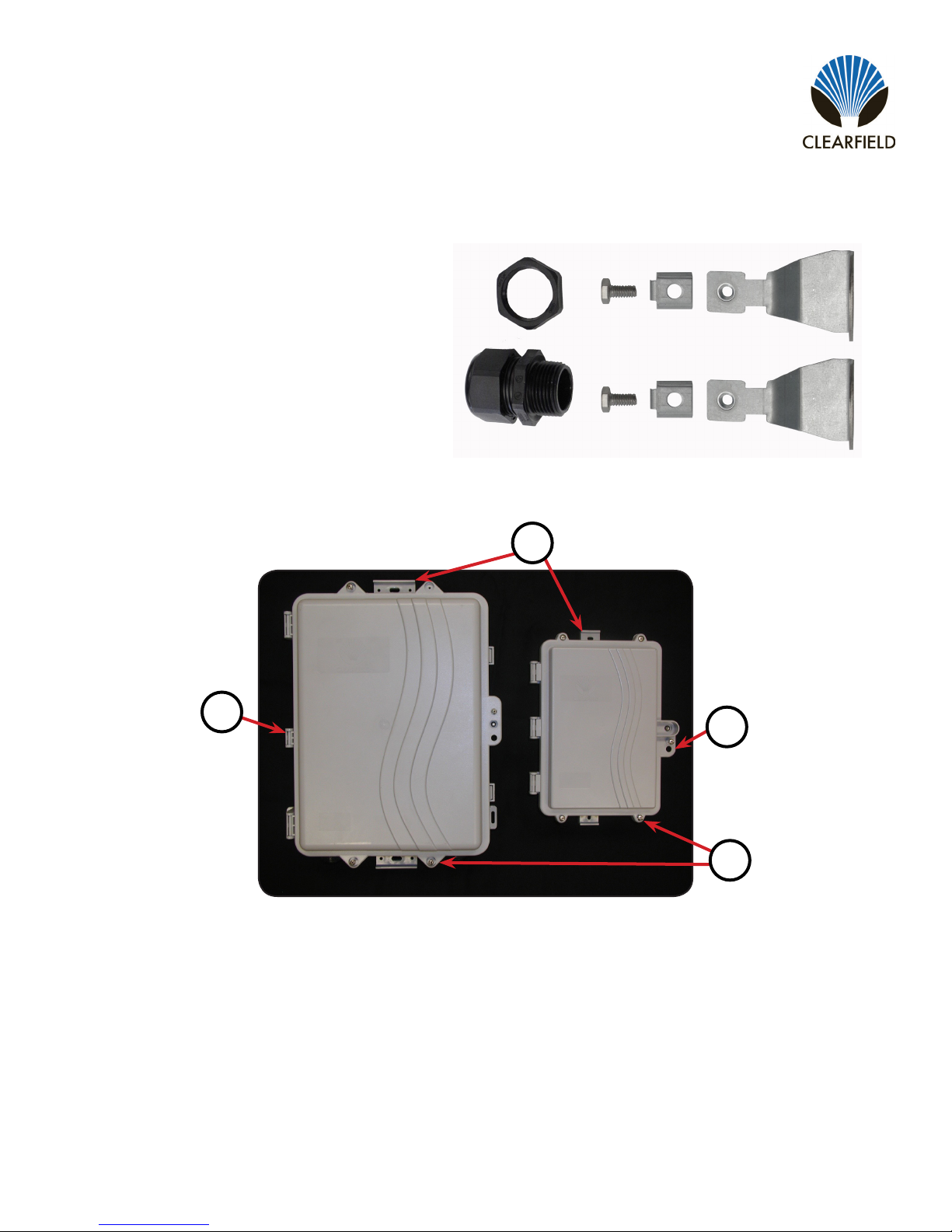
Items Included Box, Designation label, ¾” Strain relief tting(ts .51-.71”cable;),
nut, grommet for .24-.63” cable, Cassette Universal Mounting Kit
Box, ¾” Strain relief tting, nut, grommet for .24-.63”
Ideal for any small count ber scenario, the FieldSmart Small Count
Delivery (SCD) Wall Box accepts up to two Clearview®Cassettes,
providing up to 24 bers in a discrete footprint, or a single Clearview
xPAK of 6 bers in the smaller wall box, without sacricing ber
management. The lockable, NEMA 4 rated enclosure is compact,
making it ideal for a variety of applications, including harsh
environment locations surrounding ber demarcation, entrance
facilities, FTTP drop boxes and cell backhaul. Additional applications
include MDU, business class services, power and wind farms and
DOT/Trafc monitoring.
As a lower cost alternative to sheet-metal designs, this plastic, lockable,
NEMA 4 rated enclosure is consistent with Cleareld’s long-standing
reputation of delivering simple solutions for complex problems. Optimized for use with the
Clearview xPAK and Cassette, the FieldSmart Small Count Delivery Wall Box is ideal for any small count ber scenarios
where a discrete footprint without sacricing ber management is required. Standardizing on a craft-friendly, building block
architecture reduces the operating costs of ber deployment by reducing installation times and inventory carrying
requirements.
Direct: 763.476.6866 • National: 800.422.2537 • www.SeeCleareld.com • [email protected]
4
FieldSmart®Fiber Distribution Point (FDP)
SCD Indoor/Outdoor Wall Box
Installation Manual ______________________________________________________
Manual 019477 REV A - Jan 2018
Optional Items
Optional Accessory Kit (P/N FDP-xAK1) includes:
• 1 Strain relief tting and nut (sealcon)
• 2 Strength member clamps
Overview for Indoor/Outdoor Wall Box
1
3
4
FDP-XWB2 and FDP-XWB1
1. Mounting Tabs (top and bottom)
2. Hinged Side
3. Secondary Security Lock Hole
4. Screws for Additional Security
2
5
FieldSmart®Fiber Distribution Point (FDP)
SCD Indoor/Outdoor Wall Box
________________________________________________________Installation Manual
Direct: 763.476.6866 • National: 800.422.2537 • www.SeeCleareld.com • [email protected]
Manual 019477 REV A - Jan 2018
Wall box Installation
Unpack the wall box from shipping container and make sure to check for small items that may be included. These would be
bagged separately and included in the shipping container.
The wall box is installed via the 2 slots located in the top and bottom of the enclosure. Hold the panel up to the mounting
surface and mark the hole locations with a marker.
Note: A level may be used to ensure that the panel is mounted straight.
Pilot holes can then be drilled at each mark. Using appropriate fasteners for the material, attach the panel to the surface.
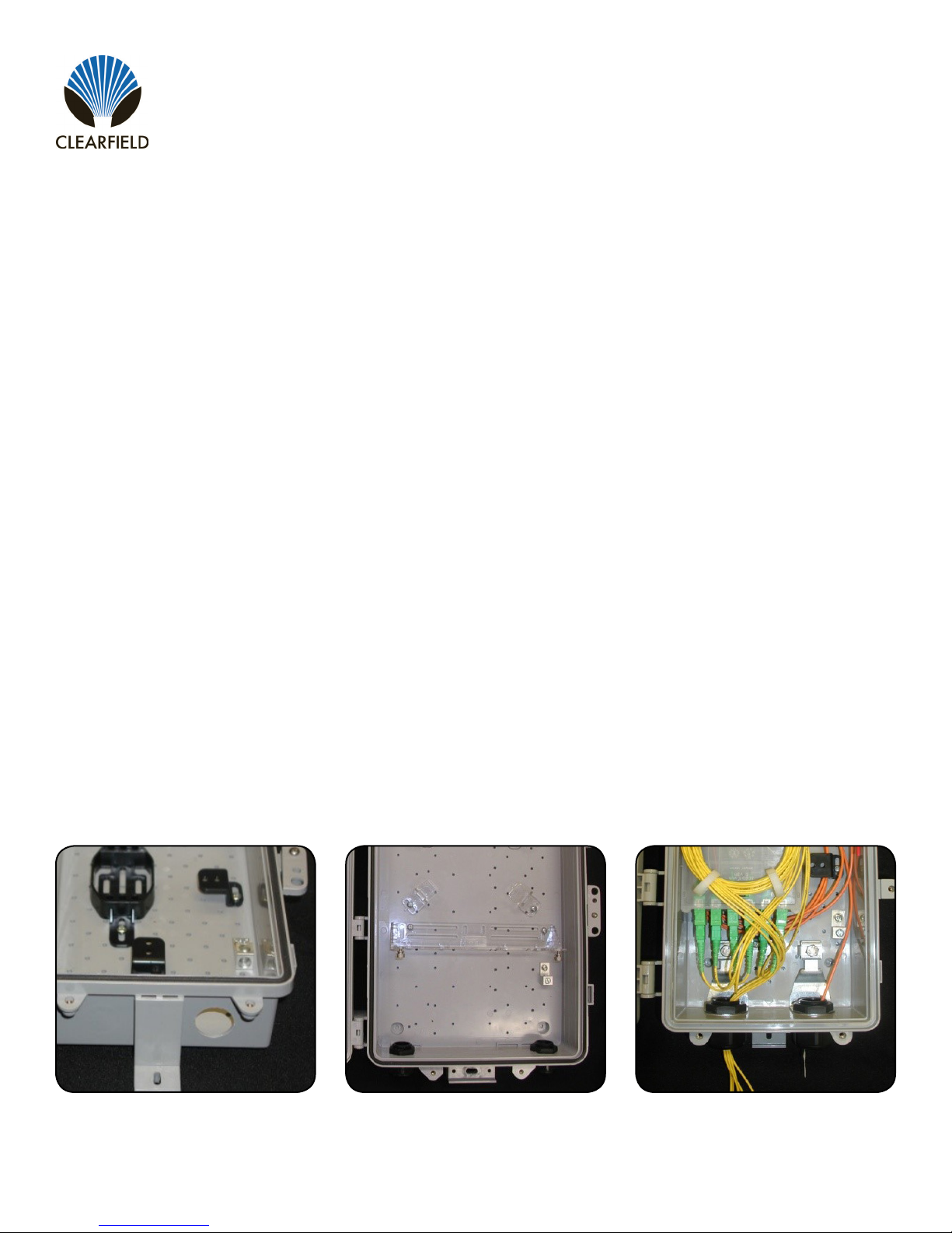
Installing Sealcons
Identify the location of the sealcon – on both size boxes, the sealcon locations have been pre-marked on the inside of
the box for easy identication. There are two sealcon locations for each box.
Use a 1” drill bit (step drill is preferred tool); drill out the plastic area enough so that the water tight strain relief tting will
t through the hole (Figure 1).
Install the sealcon through the hole, with the threads on the inside of this box.
If optional strength clamps are used, install them onto the strain relief threads before installing nut to tighten (Figure 3).
Install the nut onto the threads and tighten securely until the tting will not rotate (Figure 2).
Insert cable through sealcon and tighten dome nut to compress rubber sealing grommet.
1.
2.
3.
4.
5.
6.
Figure 1 Figure 3
Figure 2
Direct: 763.476.6866 • National: 800.422.2537 • www.SeeCleareld.com • [email protected]
6
FieldSmart®Fiber Distribution Point (FDP)
SCD Indoor/Outdoor Wall Box
Installation Manual ______________________________________________________
Manual 019477 REV A - Jan 2018
Locate the U-Mount package (P/N 012022 - typically supplied
with the xPAK)
Remove contents from plastic bag and carefully cut the
different components from the main bracket. There is an
instruction card included with each U-Mount bracket.
1.
2.
Once removed, screw the U-Mount bracket and retaining clips
into the wall box. The location for this is located on the back of
the instruction card.
3.
You are now ready to install the xPAK into the wall box. See
Clearview xPAK install manual for details. Typical cable/
jumper routing is included on the back of the instruction card.
4.
Installing U-Mount for xPAK in FDP-XWB1

7
FieldSmart®Fiber Distribution Point (FDP)
SCD Indoor/Outdoor Wall Box
________________________________________________________Installation Manual
Direct: 763.476.6866 • National: 800.422.2537 • www.SeeCleareld.com • [email protected]
Manual 019477 REV A - Jan 2018
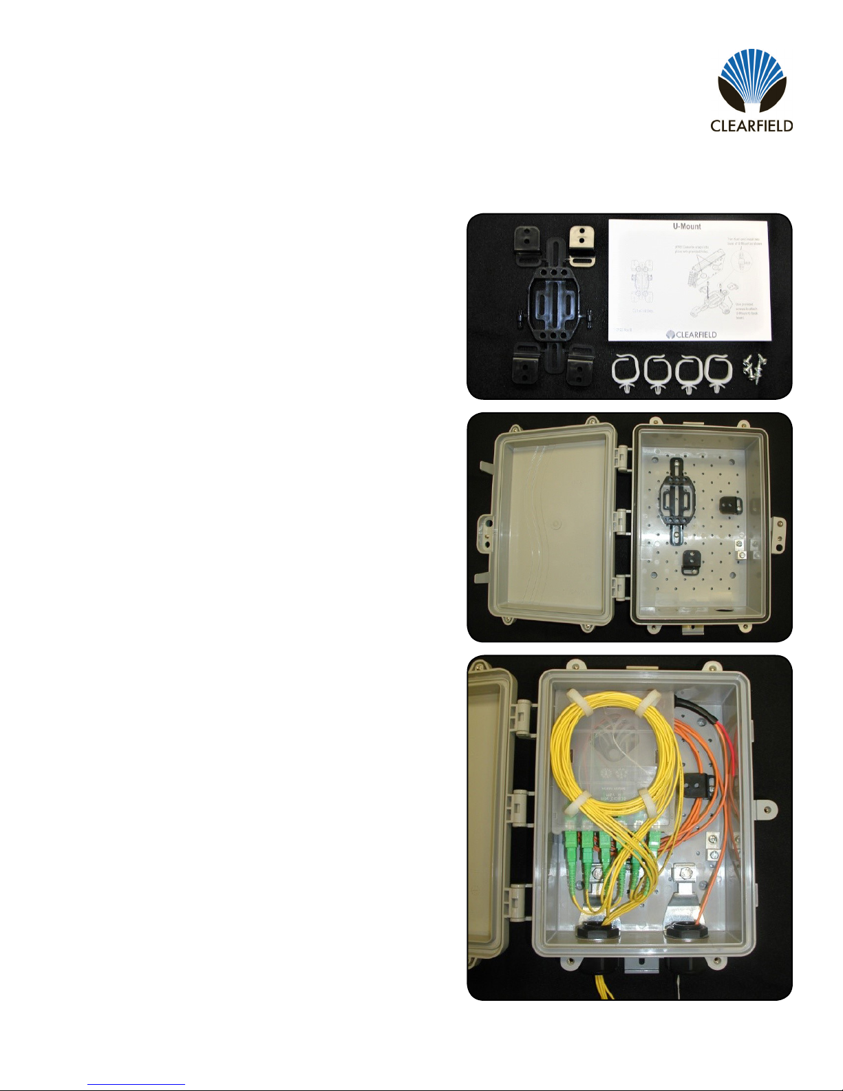
Installing Universal Cassette Mount for FDP-XWB2
Locate U-Mount package (P/N 012728) - typically shipped
separately inside of wall box.
Remove contents from plastic bag and carefully cut the different
components from the main bracket. There is an instruction card
included with each U-Mount bracket (P/N 012700).
1.
2.
Assemble U-Mount Bracket per instruction card.
Once assembled, screw the U-Mount bracket and retaining clips into the wall box. Location for this is on the back of the
instruction card (Figure 1).
You are now ready to install cassettes into wall box, using the thumb screws to fasten the cassettes to the clear
brackets (Figure 2). See Cassette installation manual for additional details.
Typical cable/jumper routing is included on the back of the instruction card.
Install designation label (shipped separately inside of wall box) – to the door. Make sure label is positioned below the
raised UL listing – located on the door of the box (Figure 3).
3.
4.
5.
6.
7.
Figure 1 Figure 3Figure 2
Direct: 763.476.6866 • National: 800.422.2537 • www.SeeCleareld.com • [email protected]
8
FieldSmart®Fiber Distribution Point (FDP)
SCD Indoor/Outdoor Wall Box
Installation Manual ______________________________________________________
Manual 019477 REV A - Jan 2018
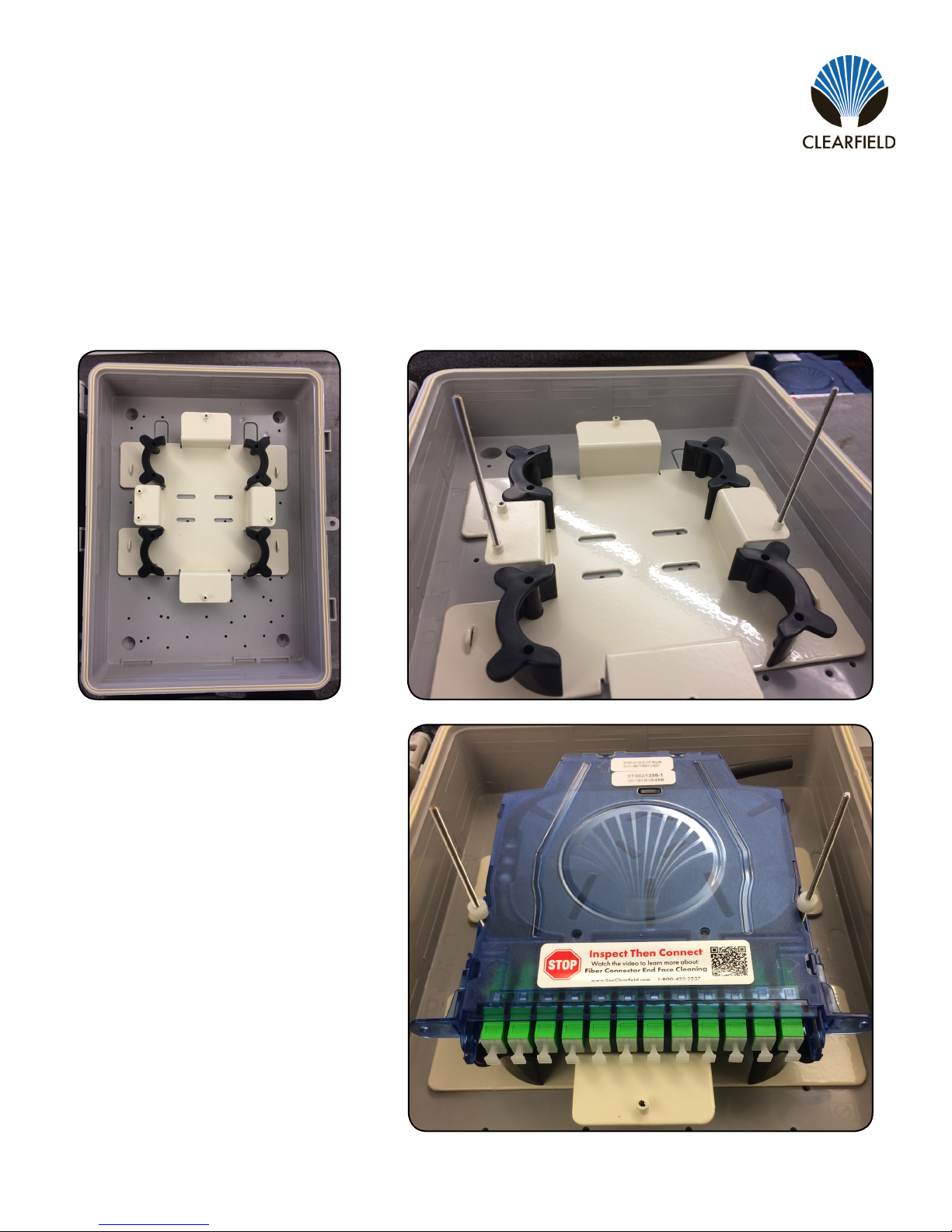
Installing Cassettes in FDP-XWB5
The FDP-XWB5 is a 5.5 inch deep version of the XWB2. Utilizing the metal plate inside the box, up to 4 Clearview Blue
Cassettes can be installed, and buffer tube slack can be routed around the outside of the radius limiters on the plate.
The wall box will arrive as shown,
with the plate installed in the box.
Twist the threaded rods into the two lower pems on the sides of
the plate. These rods will be included as a ship-along item.
1. 2.
Insert the threaded rods through the holes in
the sides of the cassettes. Slide the
cassettes down until they make contact with
the plate.
Use the provided thumb nuts to secure the
cassettes in place by threading them down
the rods and hand tightening.
3.
4.

9
FieldSmart®Fiber Distribution Point (FDP)
SCD Indoor/Outdoor Wall Box
________________________________________________________Installation Manual
Direct: 763.476.6866 • National: 800.422.2537 • www.SeeCleareld.com • [email protected]
Manual 019477 REV A - Jan 2018
Inspect Then Connect
These are Cleareld recommended products/applications. Use the product
you feel will complete your cleaning procedures. Create a “best practice” for
your company and follow those procedures.
The use of Chemtronics end face and bulkhead cleaning products and
techniques ensures a clean end face, no matter the type of contamination.
Before cleaning any connector, be sure you know what type of contaminate
you are cleaning (dry, uidic, or combination). All the available products are
good, it’s the process that you need to be aware of. Using a dry cleaning
method to clean “dirt” can lead to scratching of the end face. Learn the
process of cleaning properly.
Note: It is NOT recommended to use isopropyl alcohol to clean the end face.
Cleaning an SC/LC Connector
Cleaning the End Face
• Place one wiping paper on QbE-2 FiberSafe™ Cleaning Platen.
(Figure 1)
• Apply small amount of precision cleaner (about 1” in diameter) with
Electro-Wash MX pen on to one end of the wipe. (Figure 2)
• Hold end face at a 90 degree angle. For APC connection, adjust by
slightly tilting the container or end face. Angle is correct when no drag is
felt on the end face. (Figure 3)
• Draw end face from wet to dry part of the wipe 3 times. Use just enough
pressure to ensure complete contact between end face and the wipe.
Note: DO NOT retrace previous step.
Figure 1
Figure 2
Figure 3
Connector Cleaning Procedure
Whether factory terminated or eld spliced, clean connectors are essential for proper system operation. Even the smallest
dust particle can cause transmission problems, so for optimal network performance inspect, and if necessary, clean
connectors and adapters prior to mating.

Direct: 763.476.6866 • National: 800.422.2537 • www.SeeCleareld.com • [email protected]
10
FieldSmart®Fiber Distribution Point (FDP)
SCD Indoor/Outdoor Wall Box
Installation Manual ______________________________________________________
Manual 019477 REV A - Jan 2018
Cleaning the Ferrule
• Lightly moisten the ber optic swab (2.5mm/38542F or 1.25mm/38040)
by spotting a small amount (about 1”) of Electro-Wash PX or
Electro-Wash MX pen onto the QbE. Hold the swab, 1 side down to the
wetted area and hold for a count of 1-2-3-4-5. (Figure 4)
Figure 4
Figure 5
Figure 6
Cleaning the Mate Through an Adapter AND the Adapter Itself
• Lightly moisten the ber optic swab (2.5mm/38542F or 1.25mm/38040)
by spotting a small amount (about 1”) of Electro-Wash PX or
Electro-Wash MX pen onto the QbE. Hold the tip of the swab onto the
wetted area and hold for a count of 1-2-3-4-5.
• Insert the swab into the adapter to the connector, press lightly against
the connector, twist 2-3 times, remove and discard.
• Dry with a second dry swab.
• Inspect, repeat cleaning if necessary, and test for signal strength.
• Use additional swabs to clean inside the actual adapter. Moisten
swab, like above, and insert through hole and remove while twisting.
(Figure 6)
• Insert swab into side of ferrule, wet side to the ceramic ferrule and
circle around 2-3 times and remove. Turn swab to dry side and repeat.
(Figure 5)

11
FieldSmart®Fiber Distribution Point (FDP)
SCD Indoor/Outdoor Wall Box
________________________________________________________Installation Manual
Direct: 763.476.6866 • National: 800.422.2537 • www.SeeCleareld.com • [email protected]
Manual 019477 REV A - Jan 2018
Cleaning an MPO/MTP Connector
Female Connector
• Place one wiping paper on QbE-2 FiberSafe™ Cleaning Platen and
apply small amount of precision cleaner (about 1” in diameter) with
Electro-Wash MX pen on to one end of the wipe. (Figure 1)
Figure 1
Figure 2
Figure 3
• Hold end face at a 90 degree angle. For APC connection, adjust by
slightly tilting the container or end face. Angle is correct when no drag is
felt on the end face. (Figure 2)
Male Connector
• Lightly moisten one side of the ber optic swab (CC505F) by spotting a
small amount (about 1”) of Electro-Wash PX or Electro-Wash MX pen
onto the QbE. Hold the swab, 1 side down to the wetted area and hold
for a count of 1-2-3-4-5.
• Place swab, wet side down, at one end of connector end face and draw
across in a diagonal sweep; i.e., from ber 1 up and across to ber 12.
Turn swab over to dry and draw back from ber 12 to ber 1. (Figure 3)

Direct: 763.476.6866 • National: 800.422.2537 • www.SeeCleareld.com • [email protected]
12
FieldSmart®Fiber Distribution Point (FDP)
SCD Indoor/Outdoor Wall Box
Installation Manual ______________________________________________________
Manual 019477 REV A - Jan 2018
Standard Warranty
Cleareld warrants to the original purchaser of the Product sold hereunder is free from defects in material and workmanship under normal use and
service, subject to exceptions stated herein. Product purchased is warranted as follows: Cleareld designed and branded Products are warranted for
three (3) years: Products manufactured by Cleareld to customer prints and/or specications are warranted for one (1) year; and any Product Clear-
eld acquires from or through a third-party manufacturer or distributor and resells to Customer as the original customer will carry the manufacturer’s
pass-through warranty, if any. In all cases, the warranty period commences on the date of shipment to the original purchaser.
Warranty Claim Procedure
If any Product purchased from Cleareld is found defective under the above warranty, the following basic procedure must be followed:
1. Customer must contact Cleareld and obtain a Return Materials Authorization
2. Following authorization, the Customer ships the product-freight collect-to Cleareld’s manufacturing facility
3. Cleareld shall repair or replace the defective Product at its sole option and discretion, and return the repaired or replacement Product to Cus-
tomer’s site, freight prepaid
Note: If the Product is not found to be defective at Cleareld, the product will be returned to the Customer and the customer billed for freight in both
directions.
View our warranty policy here: https://www.seecleareld.com/warranty.html
Limitations of Warranty
Correction of defects by repair or replacement, at the option of Cleareld Inc, shall constitute the exclusive sole remedy for a breach of this limited
warranty. Cleareld shall not be liable under any circumstances for any special, consequential, incidental, punitive, or exemplary damages arising
out of or in any way connected with the product or with agreement to sell product to buyer, including, but not limited to damages for lost prots, loss
of use, or for any damages or sums paid by buyer to third parties. The foregoing limitation of liability shall apply whether the claim is based upon
principles of contract, warranty, negligence or other tort, breach of statutory duty, principles of indemnity or contribution, the failure of any limited or
exclusive remedy to achieve its essential purpose, or otherwise.
Cleareld will not be responsible for any labor or materials costs associated with installation or incorporation of Cleareld products at customer sites,
including any costs of alteration, replacement or defective product, or any eld repairs.
Other Limitations
Cleareld assumes no warranty liability regarding defects caused by:
1. Customer’s modication of Product, excepting installation activities described in Cleareld documentation
2. Customer re-packaging of Product for shipment to third parties or destinations other than those originally shipped to by Cleareld, or any de-
fects suffered during shipping where the Product has been re-packaged
3. Customer’s installation or maintenance, excepting activities described in and performed in accordance with Cleareld documentation
4. Customer’s improper or negligent use or application of Product
5. Other causes external to the Product, including but not limited to accidents, catastrophe, acts of God, government action, war, riot, strikes, civil
commotion, sovereign conduct, or the acts or conduct of any person or persons not party to or associated with Cleareld
6. Environmental factors and weathering resulting in aging and damage not necessary or applicable to the function of the product

13
FieldSmart®Fiber Distribution Point (FDP)
SCD Indoor/Outdoor Wall Box
________________________________________________________Installation Manual
Direct: 763.476.6866 • National: 800.422.2537 • www.SeeCleareld.com • [email protected]
Manual 019477 REV A - Jan 2018
Proprietary Notice
Information contained in this document is copyrighted by Cleareld, Inc. and may not be duplicated in full or part by any person without prior written
approval of Cleareld, Inc.
Its purpose is to provide the user with adequately detailed documentation to efciently install the equipment supplied. Every effort has been made to
keep the information contained in this document current and accurate as of the date of publication or revision.
However, no guarantee is given or implied that the document is error free or that it is accurate with regard to any specication.
Technical Support
Cleareld, Inc. can be contacted for any issues that arise with the supplied product.
If you need to return the supplied product, you must contact the Cleareld, Inc. Customer Service Department to request a Returned Materials
Authorization (RMA) number.
Cleareld, Inc.
7050 Winnetka Ave N
Minneapolis, MN 55428
Toll Free: 800.422.2537
Phone: 763.476.6866
Fax: 763.475.8457
Table of contents
Other Clearfield Cable Box manuals


