Clearfield FieldShield YOURx-TAP User manual
FieldShield YOURx-TAP
Installation Manual ______________________________________________________
Manual 018446 REV A - AUG 2017

Direct: 763.476.6866 • National: 800.422.2537 • www.SeeCleareld.com • [email protected]
2
FieldShield YOURx-TAP
Installation Manual _________________________________________________________
Manual 018446 REV A - AUG 2017
Table of Contents
Product Packaging 3
Parts List 3
Required Tools 4
Box Mounting 4
Preparing Ports 5
Bottom Deploy Reel Installation 5
Congurations 8
TopDeployReelInstallation 8
Installing Bulkheads 9
EnteringandExitingFiberCongurations 10
StoringSlackFiberontheTAPSlackReel 11
YOURx-TAPAccessories 12
ConnectorCleaningProcedure 13
StandardWarranty 16
ProprietaryNotice 17
TechnicalSupport 17
3
FieldShield YOURx-TAP
__________________________________________________________ Installation Manual
Direct: 763.476.6866 • National: 800.422.2537 • www.SeeCleareld.com • [email protected]
Manual 018446 REV A - AUG 2017
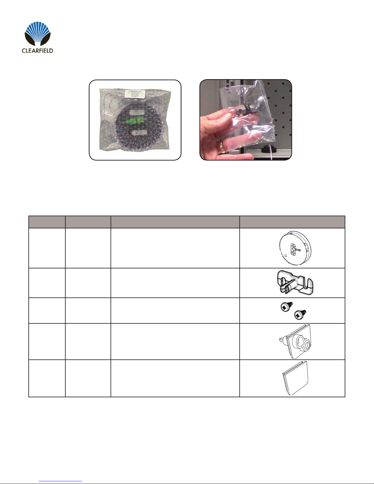
Product Packaging
StrongFiber Deploy Reels are shipped in a bubble wrap packaging (Figure1)with mounting
hardware included in a plastic pouch (Figure2).
Figure1 Figure2
Find No. Quantity Description Image
001 1 SmartFiber Deploy Reel
002 1 Back post
003 5 Self Taping Screws
004 1 Cable Entrance Bulkhead
005 1 Blank Bulkhead
Parts List
Direct: 763.476.6866 • National: 800.422.2537 • www.SeeCleareld.com • [email protected]
4
FieldShield YOURx-TAP
Installation Manual _________________________________________________________
Manual 018446 REV A - AUG 2017
Figure1
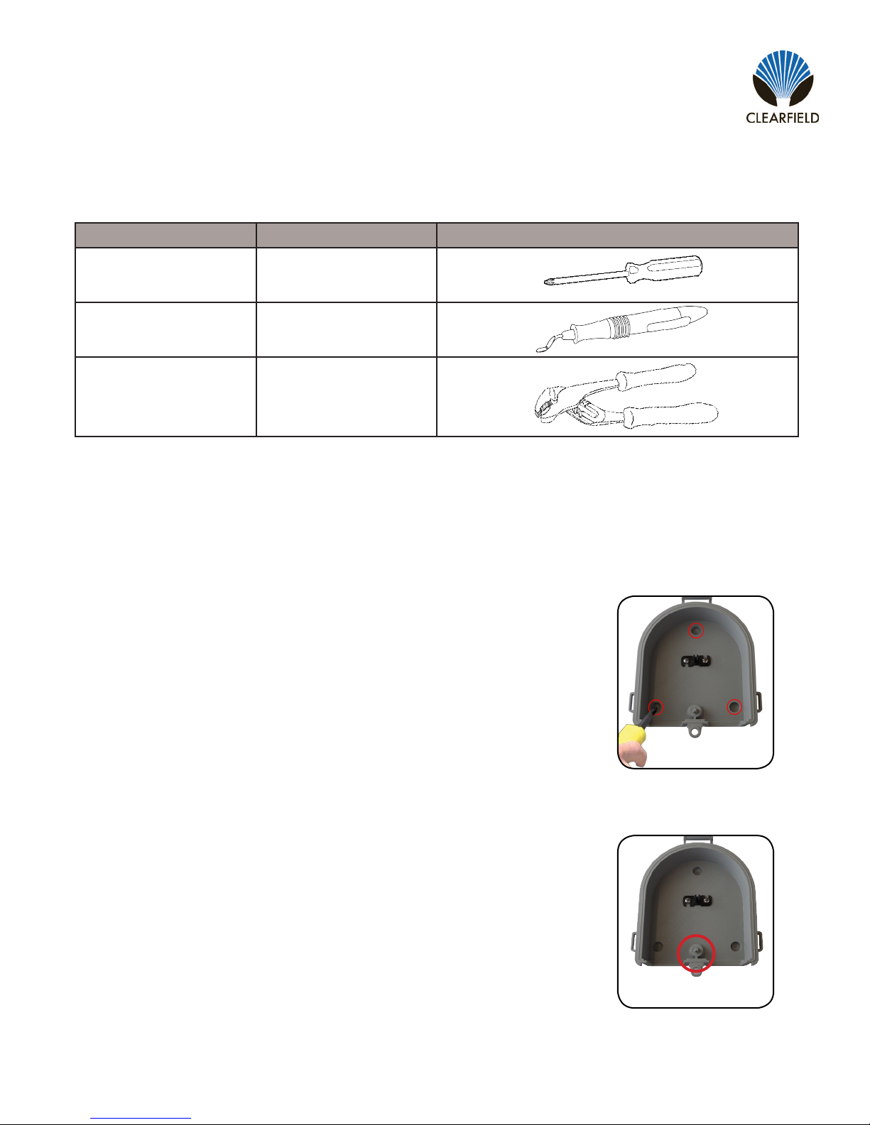
Step1:MountTAPBox
Use a Philips Screwdriver to attach the back post to wall box or mounting surface
using the provided self taping screws (Figure1).
Box Mounting
Figure2
Note: A pass through hole is provided on the back of the wall box as an option to
directly penetrate into the customer premise. (Figure2).
If this option is used a 1/4 inch hole must be drilled into the home prior to mount-
ing the TAP box. It is also recommended that the hole be sleeved with a piece of
10/6 microduct for unobstructed access into the customer premise.
Find No. Tool Image
006 Phillips Scewdriver
007 Deburring Tool
008 Pliers
Required Tools

5
FieldShield YOURx-TAP
__________________________________________________________ Installation Manual
Direct: 763.476.6866 • National: 800.422.2537 • www.SeeCleareld.com • [email protected]
Manual 018446 REV A - AUG 2017
Step1:Install Back Post
Use a Philips Screwdriver to attach the back post to wall box
or mounting surface using the provided self taping screws
(Figure 1).
Figure1
Bottom Deploy Reel Installation
Step2:Mount Deploy Reel
Align center hole on Deploy Reel with Back Post (Figure 2). The surrounding holes will be used to lock the
Reel down after installation. Press Deploy Reel onto Back Post (Figure 3).
Figure2 Figure 3
Step1:Remove Port Tab
Use a pair of pliers to snap off port tab.
(Figure 1 & Figure 2).
Step2:Ream Port
Use appropriate tool (we reccomend deburring tool)
to ream and chamfer edges of port.
(Figure 3)
Preparing Ports
Figure1 Figure2 Figure 3
Direct: 763.476.6866 • National: 800.422.2537 • www.SeeCleareld.com • [email protected]
6
FieldShield YOURx-TAP
Installation Manual _________________________________________________________
Manual 018446 REV A - AUG 2017
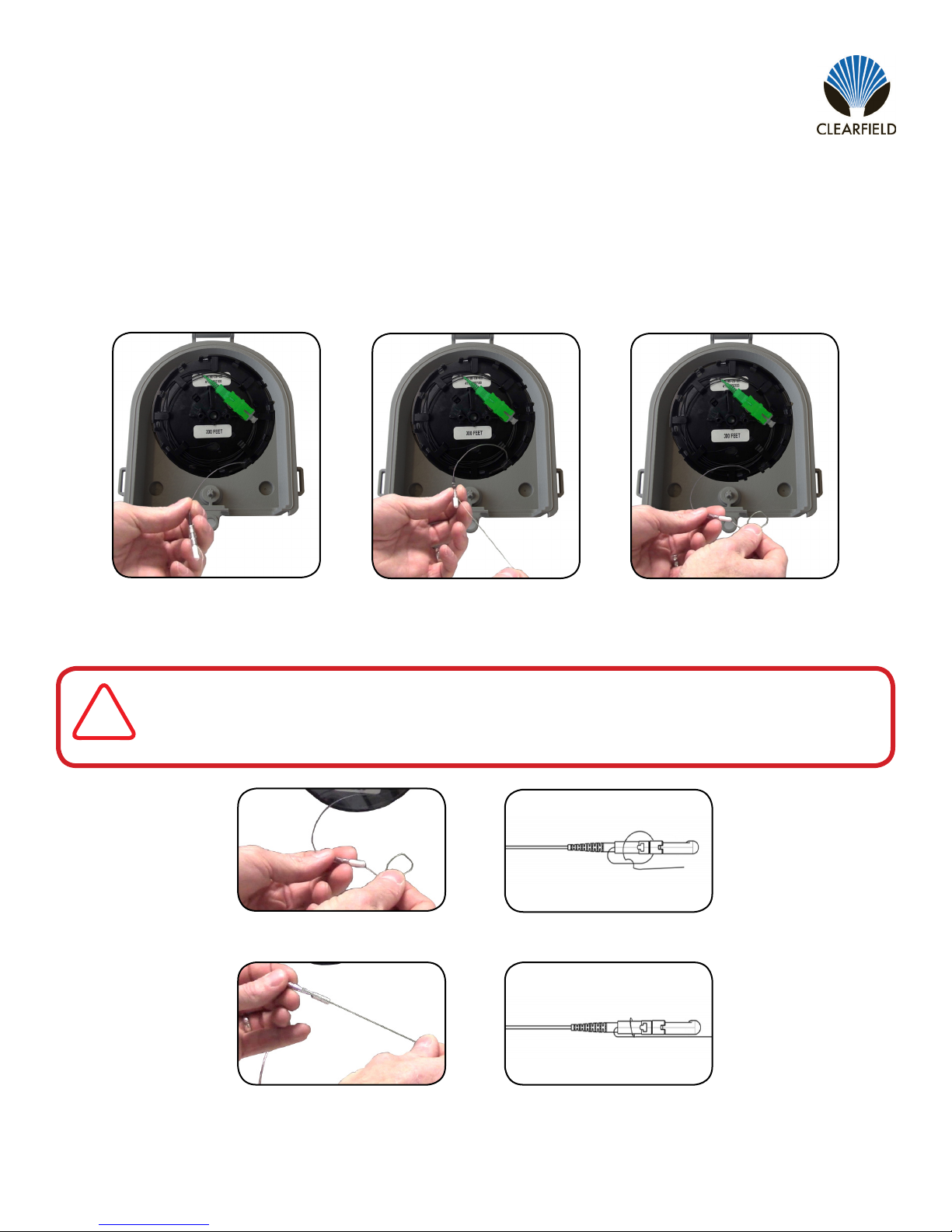
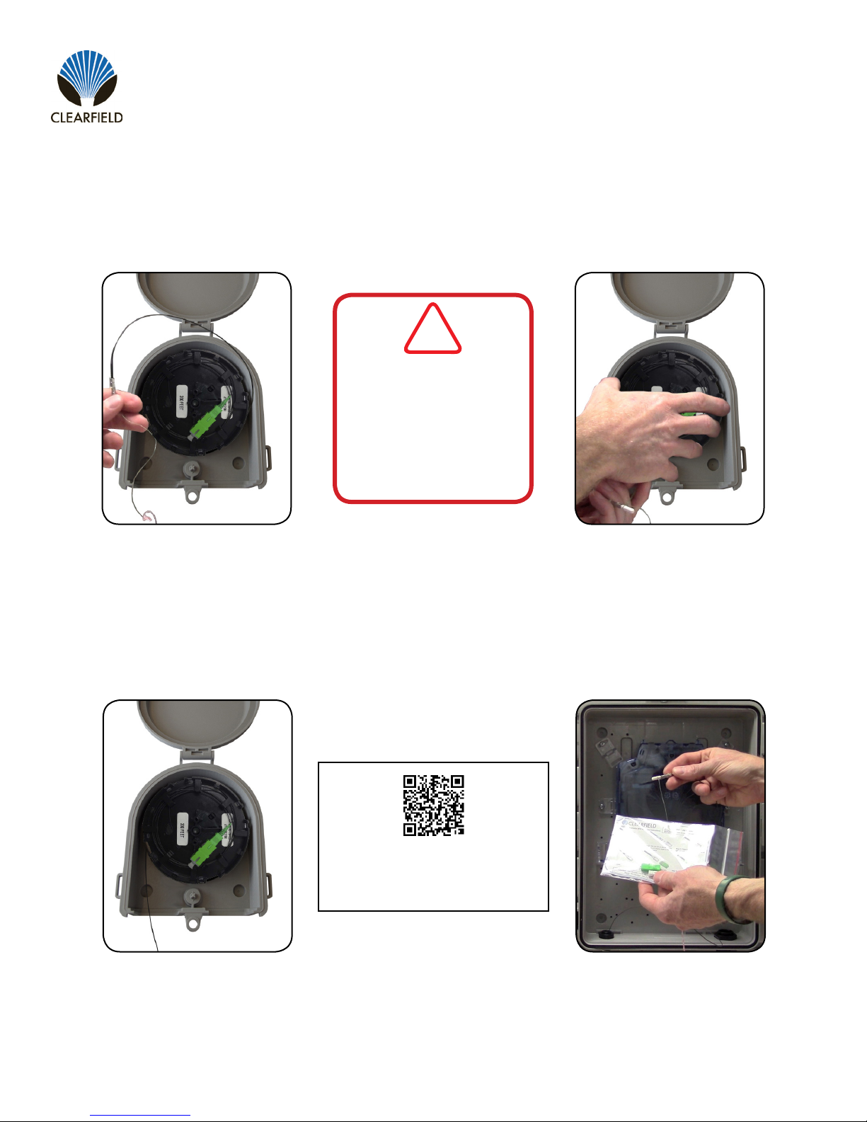
Step 3:Prepare Pullable SC Connector
Remove the Pullable SC Connector from the reel and remove protective tape (Figure 7). Find the
integrated pull string on the connector (Figure 8) and make a simple loop/half hitch in the pull string (Figure
Figure7 Figure8
Step 4:Tie Pull String to SC Connector
Loop the pull string around the rst notch on the metal crimp tube. (Figure 10 & Figure 11).
Thread the end of the pull string under itself using a half hitch knot and pull to tighten (Figure 12 & Figure 13).
Figure 9
Figure13
Figure10
Figure12
Figure11
!
IMPORTANT
7
FieldShield YOURx-TAP
__________________________________________________________ Installation Manual
Direct: 763.476.6866 • National: 800.422.2537 • www.SeeCleareld.com • [email protected]
Manual 018446 REV A - AUG 2017
Step 5:Connect Pull Strings
Tie Connector Pull String to Duct Pull String
(Figure 14).
Figure14 Figure15
Step6:Unlock Deploy Reel
Pull out gently on Deploy Reel to unlock it from
the backpost (Figure 15).
Step7:Insert Connector
Insert Connector fully into duct before
pulling ber through. (Figure 16).
Figure16
Step8:PullFiberthroughDuct
Use the Duct Pull String to pull the
required length of ber through the
duct to the network access point.
Step 9:Assemble Connector End
Once pulled throught the duct,
assemble the FieldShield Connecter
following instructions provided with
the FieldShield Reel. (Figure 17).
Figure17
Watch the Installation Video
FieldShield SC Connector
www.clfd.net/media/deployreel.php
DO NOT use any type of
tape when tying the pull
string to the microduct pull
string. This will cause friction
and will result in blockage of
the microduct.
!
IMPORTANT
Direct: 763.476.6866 • National: 800.422.2537 • www.SeeCleareld.com • [email protected]
8
FieldShield YOURx-TAP
Installation Manual _________________________________________________________
Manual 018446 REV A - AUG 2017
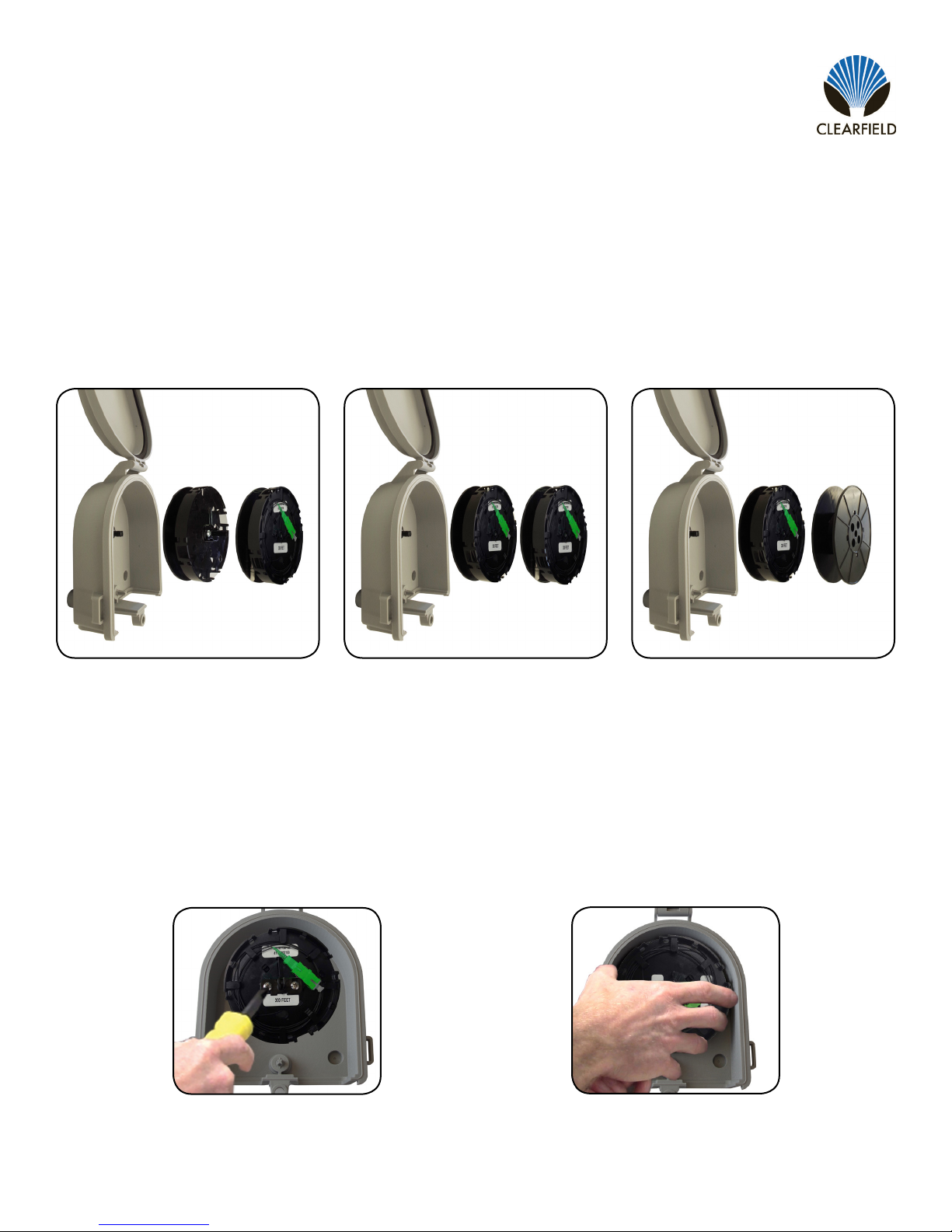
Conguration1:
Bottom: Empty Deploy Reel
Top: StrongFiber Delpoy Reel
(Figure 1).
Figure1
Congurations
The FieldShield YOURx-TAP can be used in the following congurations.
Figure2 Figure 3
Conguration2:
Bottom: StrongFiber Deploy Reel
Top: StrongFiber Delpoy Reel
(Figure 2).
Conguration3:
Bottom: StrongFiber Deploy Reel
Top: FLEXdrop Slack Reel
(Figure 3).
Top Deploy Reel Installation
Figure2
Step2:Mount Deploy Reel
Align center hole on Deploy Reel with Back Post.
Press Deploy Reel onto Back Post (Figure 2).
Figure2
Step1:Install Back Post
Use a Philips Screwdriver to attach the back post
to bottom Deploy Reel using the provided self
taping screws (Figure 1).
Note: Back post cannot be secured to FLEXdrop
slack reel.
9
FieldShield YOURx-TAP
__________________________________________________________ Installation Manual
Direct: 763.476.6866 • National: 800.422.2537 • www.SeeCleareld.com • [email protected]
Manual 018446 REV A - AUG 2017
Figure1
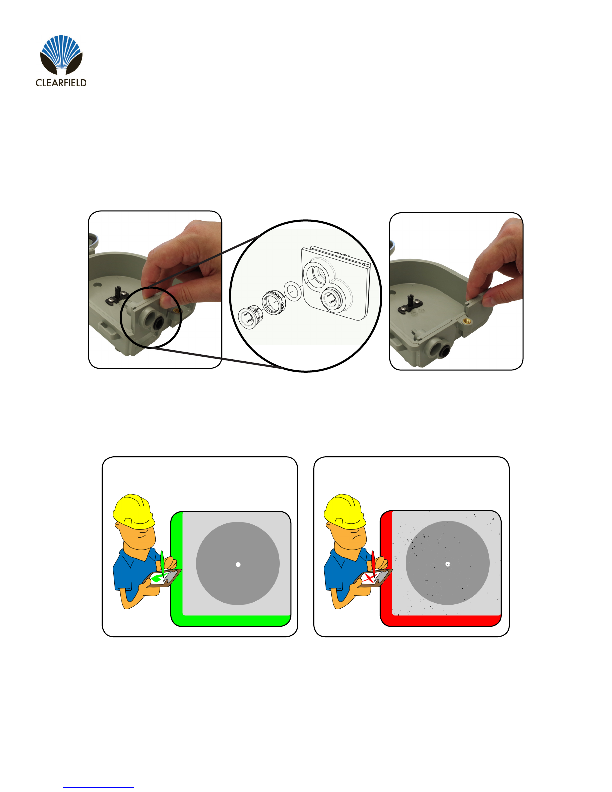
Installing Bulkheads
The YOURx-TAP is shipped with Qty (1) Cable Entrance Bulkhead (Figure 1) Qty (1) Blank Bulkhead (Figure 2). Additional
Bulkheads are available for custom congurations.
Figure2
INSPECT BEFORE YOU CONNECT!
CLEAN CONNECTOR DIRTY CONNECTOR
SEE PAGE 13 FOR RECOMMENDED CLEANING PROCEDURES
Direct: 763.476.6866 • National: 800.422.2537 • www.SeeCleareld.com • [email protected]
10
FieldShield YOURx-TAP
Installation Manual _________________________________________________________
Manual 018446 REV A - AUG 2017
Figure1
Step1:Feed through
Port
Guide preconnectorized
ber (unassembled) into
YOURx-TAP port and pull
until hardened connector
reaches port. (Figure1).
Step2:Seat Connector
Once ber is through,
seat connector into port.
(Figure2).
Figure2
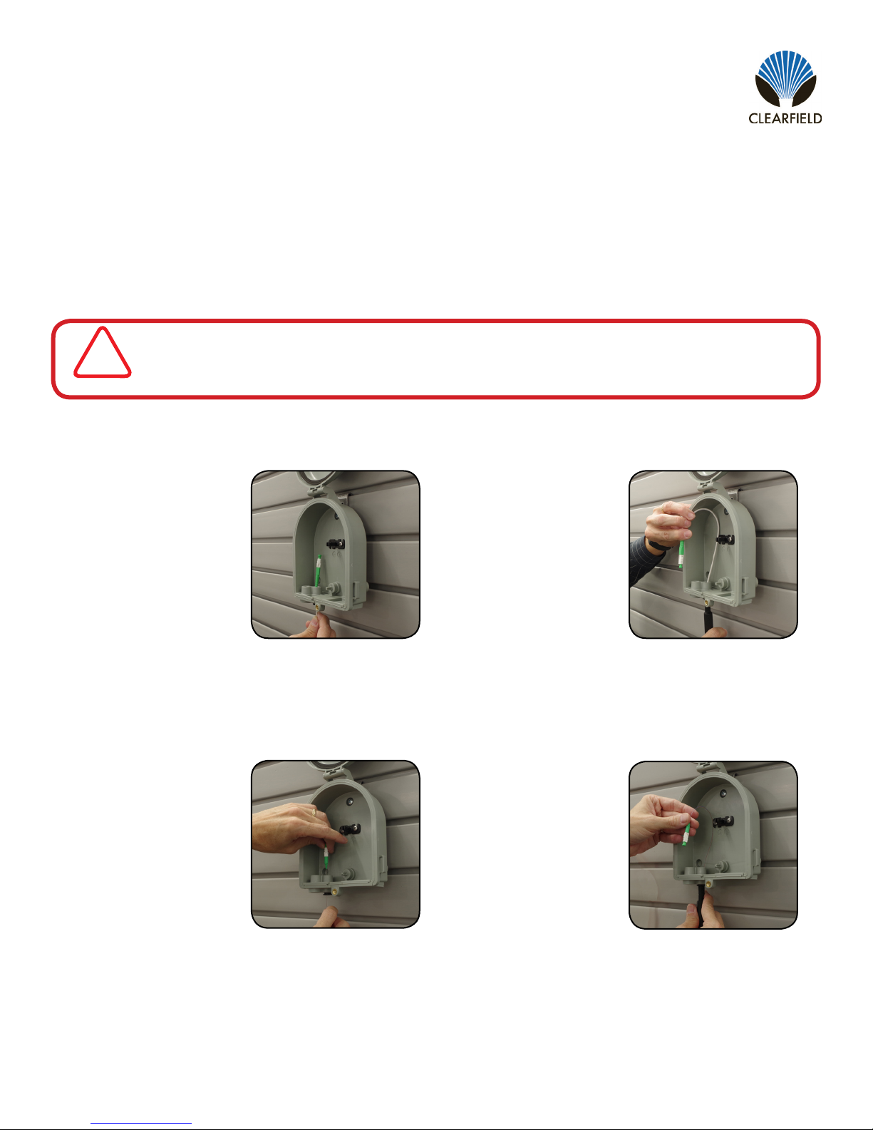
EnteringandExitingFiberCongurations
Fiber can enter or exit the YOURx-TAP through the removable bulkheads at the bottom of the unit, or through the pass
through port at the back ot the unit.
When entering the YOURx-TAP DO NOT assemble SC Connector Outer Housing until ber has been
passed through the port. Fully connectorized ber will not pass through port.
!
IMPORTANT
Figure1 Figure2
FieldShield Flat-SC
FieldShield D-ROP
Step1:Feed through
Port
Guide preconnectorized
ber (unassembled) into
YOURx-TAP port and pull
until hardened connector
reaches port. (Figure1).
Step2:Seat Connector
Once ber is through,
seat connector into port.
(Figure2).

11
FieldShield YOURx-TAP
__________________________________________________________ Installation Manual
Direct: 763.476.6866 • National: 800.422.2537 • www.SeeCleareld.com • [email protected]
Manual 018446 REV A - AUG 2017
Figure1 Figure2
Figure1 Figure2
FieldShield FLEXdrop or FieldShield
FieldShield StrongFiber
Step1:Install Duct
Seat microduct into
YOURx-TAP port.
(Figure1).
Step2:Feed through
Duct
Push or pull ber
(unassembled) through
the duct and into the
YOURx TAP. (Figure2).
Step1:Install Duct
Seat microduct into
YOURx-TAP port and tie
StrongFiber pull string to
duct pullstring with double
knot. (Figure1).
Step2:Feed through
Duct
Release deploy reel and
pull ber (unassembled)
out through the duct and
into the YOURx TAP.
(Figure2).
Storing Slack Fiber on the TAP Slack Reel
Up to 50 feet of FieldShield or FieldShield FLEXdrop can be stored on the TAP Slack Reel.
Figure1 Figure2
Step1:Coil Fiber
Once ber has been
terminated in the Strong-
Fiber Deploy Reel, wrap
excess ber around the
the TAP Slack Reel in a
counter-clockwise motion,
making sure not to intro-
duce a twist to the ber.
(Figure1).
Step2:Mount Reel
Mount TAP Slack Reel
onto back post attached
to StrongFiber Deploy
Reel. (Figure2).

Direct: 763.476.6866 • National: 800.422.2537 • www.SeeCleareld.com • [email protected]
12
FieldShield YOURx-TAP
Installation Manual _________________________________________________________
Manual 018446 REV A - AUG 2017
Part Number Description
018664 FlexPort Plug, ller for 10mm Cartridges
Part Number Description
FSX-10MM EXPANSION KIT Bag of four 10mm FlexPorts and 10mm Plugs
Part Number Description
016280 FlexPort, Push to Connect, 10mm
Part Number Description
016280 FlexPort, Push to Connect, 10mm
FS-GBLOCK-10MM-04
Description
Fits around ber onto duct, providing gas-tight protection. The FS-GBLOCK-10MM-04
includes 4 - 10mm gas blockers and 4 - 3” of 10mm FieldShield Microduct.
Pre-ConguredPartNumbers
FSX-10mmExpansionKit
Description
Bag of 4 individual FlexPorts (016280) and 4 - 10mm FlexPorts plugs (018664) for securing
10mm microduct into the YOURx-TAP.
Pre-ConguredPartNumbers
10MMPlug
Description
FieldShield FlexPort ller plug for 10mm into the YOURx-TAP.
Application: Used for sealing FlexPort holes if plug on the inside is removed.
Pre-ConguredPartNumbers
FieldShield FlexPort
Description
Individual FieldShield FlexPort for securing 10mm or 14mm microduct into the FieldShield
YOURx-Terminal or YOURx-TAP. Includes the outer coupler, inner housing and O-ring.
Pre-ConguredPartNumbers
YOURx-TAP Accessories

13
FieldShield YOURx-TAP
__________________________________________________________ Installation Manual
Direct: 763.476.6866 • National: 800.422.2537 • www.SeeCleareld.com • [email protected]
Manual 018446 REV A - AUG 2017
Whether factory terminated or eld spliced, clean connectors are essential
for proper system operation. Even the smallest dust particle can cause
transmission problems, so for optimal network performance, inspect and if
necessary, clean all connectors and adapters prior to mating.
I.B.Y.C…InspectBeforeYouConnect!
ALWAYS inspect the connector rst thing with a clean ber scope inspect
the pair. Three types of contamination require different cleaning techniques.
The use of Chemtronics end face and bulkhead cleaning products and
techniques ensures a clean end face, no matter the type of contamination.
These are Cleareld recommended products/application. Use the product
you feel will complete your cleaning procedures. Create a “best practice” for
your company and follow those procedures.
**NOTE: It is NOT recommended to use IPA to clean the end-face.
Cleaningtheend-face…butnotjusttheend-face
• Place one wiping paper on QbE-2 FiberSafe™ Cleaning Platen. Figure1
• Apply small amount of precision cleaner (about 1” in diameter) with Elec-
tro-Wash MX pen on to one end of the wipe. Figure2
• Hold end face 90 degree. Adjust for APC connection by slightly tilting the
container or end face. Angle is correct when no drag is left on the end face.
Figure 3
• Draw end face from wet to dry part of the wipe 3 times. Use just enough
pressure to ensure complete contact between end face and the wipe.
DO NOT retrace previous step.
Figure 1
Figure 2
Figure 3
Connector Cleaning Procedure

Direct: 763.476.6866 • National: 800.422.2537 • www.SeeCleareld.com • [email protected]
14
FieldShield YOURx-TAP
Installation Manual _________________________________________________________
Manual 018446 REV A - AUG 2017
• CLEAN THE FERRULE…Lightly moisten the ber optic swab
(2.5mm/38542F or 1.25mm/38040) by spotting a small amount (about
1”) of Electro-Wash PX or Electro-Wash MX pen onto the Qbe. Hold the
swab, 1 side down to the wetted area and hold for a count of 1-2-3-4-5.
Figure 4
• Insert swab into side of ferrule, wet side to the ceramic ferrule and
circle around 2-3 times and remove. Turn swab to dry side and repeat.
Figure 5
Cleaning the mate through a bulkhead adapter AND the
adapteritself!
• Lightly moisten the ber optic swab(2.5mm/38542F or 1.25mm/38040)
by spotting a small amount (about 1”) of Electro-Wash PX or Elec-
tro-Wash MX pen onto the Qbe. Hold the tip of the swab onto the wetted
area and hold for a count of 1-2-3-4-5.
• Insert the swab into the adapter to the connector, press lightly against
the connector, twist 2-3 times, remove and discard.
• Dry with a second dry swab.
• Inspect (re-clean if necessary) and test for signal strength.
• Use additional swabs to clean inside the actual adapter. Moisten swab,
like above, insert through hole and remove while twisting. Figure6
Figure 4
Figure 5
Figure 6

15
FieldShield YOURx-TAP
__________________________________________________________ Installation Manual
Direct: 763.476.6866 • National: 800.422.2537 • www.SeeCleareld.com • [email protected]
Manual 018446 REV A - AUG 2017
Cleaning an MPO/MTP Connector
Female Connector
• Place one wiping paper on QbE-2 FiberSafe™ Cleaning Platen and
apply small amount of precision cleaner (about 1” in diameter) with Elec-
tro-Wash MX pen on to one end of the wipe. Figure1
• Hold end face 90 degree. Adjust for APC connection by slightly tilting
the container or end face. Angle is correct when no drag is left on the end
face. Figure2
Male Connector
• Lightly moisten the ber optic swab (CC505F) like above, moistening 1
side.
• Place swab, wet side down at one end of connector end-face and draw
across in a diagonal sweep (ie: from ber 1 up and across to ber 12).
Turn swab over to dry and draw back from ber 12 to ber 1. Figure 3
BEFORE cleaning any connector…be sure you know what type of con-
taminate you are cleaning…dry? Fluidic?...All the available products are
good, it’s the process that you need to be aware of. Using a dry cleaning
method to clean “dirt” can lead to scratching of the end-face. Learn the
process of cleaning properly!
Figure 1
Figure 2
Figure 3

Direct: 763.476.6866 • National: 800.422.2537 • www.SeeCleareld.com • [email protected]
16
FieldShield YOURx-TAP
Installation Manual _________________________________________________________
Manual 018446 REV A - AUG 2017
Standard Warranty
Cleareld warrants to the original purchaser of the Product sold hereunder is free from defects in material and workmanship under normal use and
service, subject to exceptions stated herein. Product purchased is warranted as follows: Cleareld designed and branded Products are warranted for
ve (5) years: Products manufactured by Cleareld to customer prints and/or specications are warranted for one (1) year; and any Product Clear-
eld acquires from or through a third-party manufacturer or distributor and resells to Customer as the original customer will carry the manufacturer’s
pass-through warranty, if any. In all cases, the warranty period commences on the date of shipment to the original purchaser.
Warranty Claim Procedure
If any Product purchased from Cleareld is found defective under the above warranty, the following basic procedure must be followed:
1. Customer must contact Cleareld and obtain a Return Materials Authorization
2. Following authorization, the Customer ships the product-freight collect-to Cleareld’s manufacturing facility
3. Cleareld shall repair or replace the defective Product at its sole option and discretion, and return the repaired or replacement Product to Cus-
tomer’s site, freight prepaid
Note: If the Product is not found to be defective at Cleareld, the product will be returned to the Customer and the customer billed for freight in both
directions.
Limitations of Warranty
Correction of defects by repair or replacement, at the option of Cleareld Inc, shall constitute the exclusive sole remedy for a breach of this limited
warranty. Cleareld shall not be liable under any circumstances for any special, consequential, incidental, punitive, or exemplary damages arising
out of or in any way connected with the product or with agreement to sell product to buyer, including, but not limited to damages for lost prots, loss
of use, or for any damages or sums paid by buyer to third parties. The foregoing limitation of liability shall apply whether the claim is based upon
principles of contract, warranty, negligence or other tort, breach of statutory duty, principles of indemnity or contribution, the failure of any limited or
exclusive remedy to achieve its essential purpose, or otherwise.
Cleareld will not be responsible for any labor or materials costs associated with installation or incorporation of Cleareld products at customer sites,
including any costs of alteration, replacement or defective product, or any eld repairs.
Other Limitations
1. Cleareld assumes no warranty liability regarding defects caused by:
2. Customer’s modication of Product, excepting installation activities described in Cleareld documentation
3. Customer re-packaging of Product for shipment to third parties or destinations other than those originally shipped to by Cleareld, or any de-
fects suffered during shipping where the Product has been re-packaged
4. Customer’s installation or maintenance, excepting activities described in and performed in accordance with Cleareld documentation
5. Customer’s improper or negligent use or application of Product
6. Other causes external to the Product, including but not limited to accidents, catastrophe, acts of God, government action, war, riot, strikes, civil
commotion, sovereign conduct, or the acts or conduct of any person or persons not party to or associated with Cleareld

17
FieldShield YOURx-TAP
__________________________________________________________ Installation Manual
Direct: 763.476.6866 • National: 800.422.2537 • www.SeeCleareld.com • [email protected]
Manual 018446 REV A - AUG 2017
Proprietary Notice
About FieldShield Product Line Application
Information contained in this document is copyrighted by Cleareld, Inc. and may not be duplicated in full or part by any person without prior written
approval of Cleareld, Inc.
Its purpose is to provide the user with adequately detailed documentation to efciently install the equipment supplied. Every effort has been made to
keep the information contained in this document current and accurate as of the date of publication or revision.
However, no guarantee is given or implied that the document is error free or that it is accurate with regard to any specication.
Technical Support
Cleareld, Inc. can be contacted for any issues that arise with the supplied product.
If you need to return the supplied product, you must contact the Cleareld, Inc. Customer Service Department to request a Returned Materials
Authorization (RMA) number.
Cleareld, Inc.
7050 Winnetka Ave N
Minneapolis, MN 55428
Toll Free: 800.422.2537
Phone: 763.476.6866
Fax: 763.475.8457
Table of contents
Other Clearfield Cable Box manuals


Popular Cable Box manuals by other brands

VISSEM Electronics
VISSEM Electronics Opticube VSOF-OTB-E manual

KS Tools
KS Tools efuturo Wallbox operating instructions

Sanus
Sanus SA808 instruction manual

Minebea Intec
Minebea Intec PR 6130/68S installation manual

Pentair
Pentair Raychem JBS-100-E manual

Sanus Systems
Sanus Systems ELM301 quick start guide


