Cleco LIVEWIRE TMEC-200 Series Owner's manual

For additional product information visit our website at http://www.apexpowertools.com
Programming manual
P1934E/EN
2009-04
Electric Tool Control
Serie TMEC-200
Version 2.03.08

2 P1934E/EN 2009-04 en00c381.fm, 23.04.2009
About this programming manual
This programming manual is the – original programming manual – and is intended for all persons
who configure settings on the TMEC-200 controller.
The programming manual does the following:
• It provides important instructions for safe and effective operation.
• It describes the function and operation of the TMEC-200 controller.
• It points out options.
The following documents provide additional information for operating the cordless EC tools with
the TMEC-200 controller:
PL12-1405 Parts Manual TMEC-200
P1890E Instruction Manual 17BP
P1891E Instruction Manual 47BA
P1892E Operating instructions Base Station
P1894E Installation instructions Cordless EC toolwith WLAN data transmission
Symbols in the text:
➔Identifies instructions to be followed.
•Identifies enumerations.
italics Identifies menu items, i. e.: Diagnostics
<…> Identifies elements that have to be selected or deselected, such as buttons or
control boxes, i. e.: <F5>
Courier Identifies the names of paths and files, i. e.: setup.exe
\A backslash between two names identifies selection of an item from the menu,
i. e.: file \ print
Disclaimer:
Apex Tool Group reserves the right to modify, supplement or improve this document or the product
without prior notice. This document may not be reproduced in whole or in part in any way, shape
or form, or copied to another natural or machine-readable language or to a data carrier, whether
electronic, mechanical, optical or otherwise, without the express permission of Apex Tool Group.

P1934E-EN_2009-04_TMEC200_V2.03.08IVZ.fm, 23.04.2009 P1934E/EN 2009-04 3
Contents
1 Getting started 7
1.1 Workplace safety symbol...................................................................... 7
1.2 Checking your unit ................................................................................ 7
1.3 Software................................................................................................ 7
1.4 Installing the unit................................................................................... 7
1.4.1 General information .............................................................................. 7
1.4.2 Assembly .............................................................................................. 8
1.4.3 Location considerations ........................................................................ 8
1.4.4 Power source........................................................................................ 8
1.4.5 Intended use ......................................................................................... 8
1.4.6 EMC measures ..................................................................................... 9
1.5 Connecting the unit............................................................................... 9
1.5.1 General information .............................................................................. 9
1.6 Switching on the unit........................................................................... 10
1.7 Communication with cordless EC tool ................................................ 11
1.8 System overview................................................................................. 13
2 Controller specifications 15
2.1 Understanding the keypad.................................................................. 15
2.2 Technical data..................................................................................... 16
2.2.1 Housing............................................................................................... 16
2.2.2 Display ................................................................................................ 16
2.2.3 Keypad overlay ................................................................................... 16
2.2.4 CPU with PC 104................................................................................ 17
2.2.5 AC power supply................................................................................. 18
2.2.6 Internal DC power supply ................................................................... 18
2.2.7 Input / output connectors .................................................................... 18
3 Programming 21
3.1 Navigator Menu .................................................................................. 21
3.1.1 Basic Navigation instructions.............................................................. 21
3.1.2 Password function .............................................................................. 22
3.1.3 Multiple channel functions: General description ................................. 22
3.1.4 Navigator Menu .................................................................................. 22
3.2 Basic Application Builder .................................................................... 24
3.2.1 Basic parameters for torque control / angle monitoring ...................... 25
3.2.2 Basic parameters for angle control / torque monitoring ...................... 25
3.2.3 Basic Application Builder parameters ................................................. 25
3.2.4 Advanced parameter default values ................................................... 26
3.2.5 Basic Application Builder / Copy......................................................... 26
3.3 Standard Application Builder............................................................... 27
3.3.1 Standard Application Builder / View Stages........................................ 27

4 P1934E/EN 2009-04 P1934E-EN_2009-04_TMEC200_V2.03.08IVZ.fm, 23.04.2009
3.3.2 Standard Application Builder / View Stages / Copy ............................ 28
3.3.3 Standard Application Builder / Select Sequence ................................ 29
3.3.4 Standard Application Builder / Parameters ......................................... 32
3.3.5 Standard Application Builder / Advanced Parameters ........................ 38
3.4 Advanced............................................................................................ 39
3.4.1 Advanced Application Builder / Application Matrix.............................. 39
3.4.2 Advanced Application Builder / Inputs – only for TMEB-200 / TMEC . 40
3.4.3 Advanced Application Builder / Outputs – only for TMEB-200 / TMEC 42
3.4.4 Advanced / Linking ............................................................................. 44
3.4.5 Advanced / System Settings............................................................... 45
3.5 RUN Screen........................................................................................ 48
3.5.1 Run Screen / Configuration ................................................................ 51
3.6 Oscilloscope ....................................................................................... 52
3.7 Communications ................................................................................. 53
3.7.1 Communications / Ethernet ................................................................ 53
3.7.2 Communication / Part ID..................................................................... 58
3.7.3 Communications / Printer ................................................................... 61
3.7.4 Communication / Tool ......................................................................... 62
3.7.5 Infrared data transmission .................................................................. 63
3.7.6 868 MHz data transmission ................................................................ 64
3.7.7 WLAN data transmission .................................................................... 67
3.8 Tool Setup........................................................................................... 73
3.9 Statistics.............................................................................................. 74
3.9.1 Statistics / Chronological History ........................................................ 74
3.9.2 Statistics / Charts ................................................................................ 75
3.9.3 Statistical Parameter........................................................................... 78
3.10 Diagnostics ......................................................................................... 79
3.10.1 Inputs / Outputs – only for TMEB-200 / TMEC ................................... 79
3.10.2 Tool / Tool Memory.............................................................................. 80
3.10.3 Serial................................................................................................... 80
3.11 Utilities ................................................................................................ 81
3.11.1 Utilities / Software ............................................................................... 81
3.11.2 Utilities / Tool....................................................................................... 82
3.11.3 Utility / System settings – only for TMEB-200 / TMEC ....................... 83
3.12 Administration ..................................................................................... 84
3.12.1 Administration / Load .......................................................................... 84
3.12.2 Administration / Save.......................................................................... 85
3.12.3 Administration / Print........................................................................... 86
3.12.4 Administration / Password .................................................................. 87
3.12.5 Administration / Date & Time .............................................................. 88
3.12.6 Administration / Language .................................................................. 89
3.12.7 Administration / Counters ................................................................... 90
4 Troubleshooting 91

P1934E-EN_2009-04_TMEC200_V2.03.08IVZ.fm, 23.04.2009 P1934E/EN 2009-04 5
5 Statistics 97
5.1 Understanding Statistics ..................................................................... 97
5.1.1 The Nature of Variation....................................................................... 97
5.1.2 The Normal Curve .............................................................................. 98
5.1.3 The Procedure .................................................................................... 98
5.1.4 System Improvement........................................................................ 102
5.2 Statistic Symbols............................................................................... 103
6 Glossary 105

6 P1934E/EN 2009-04 P1934E-EN_2009-04_TMEC200_V2.03.08IVZ.fm, 23.04.2009

en01c381.fm, 23.04.2009 P1934E/EN 2009-04 7
Getting started 1
1 Getting started
1.1 Workplace safety symbol
!
This warning sign identifies all notes on safe work practices in this operator's manual,
alerting to hazards to life and health of personnel. Observe these notes and proceed with
special care in the cases described. Pass all safety instructions on to other operators. In
addition to the safety instructions in these operating instructions, the general local safety
and accident prevention rules must be observed.
ATTENTION! The signal word "Attention" identifies all portions of these operating instructions meriting
special attention to ensure that guidelines, rules, hints and the correct work procedures
are observed and to prevent damage to and destruction of the machine and/or parts.
1.2 Checking your unit
Take the time to ensure you have the required peripheral equipment and cables necessary to
setup and run your unit. If you do not have all the necessary items, contact your distributor.
Refer to Attachment A.1, page 12 for illustration of your unit.
1.3 Software
Your unit has been pre-loaded with software version 2.03.08 and requires no additional software
to begin your fastening process. If you are interfacing your unit with an external computer, inter-
facing software is required. Contact your distributor for the interfacing software.
1.4 Installing the unit
1.4.1 General information
!
It is mandatory that national, state and local safety and wiring standards be followed dur-
ing installation. These standards take precedence over any information presented in this
section.
To avoid the hazard of electrical shock or burn, the following instructions must be
adhered to. Failure to follow these instructions may also cause damage to your unit and
void existing warranties.
• Do not energize the unit until all connections have been properly made.
• Equipment must be properly grounded before applying power. Units energized by cord
and plug must be connected to an approved and properly grounded receptacle.
• All units must be energized by an isolated line.
• The unit door must always be closed and secured prior to energizing the unit.
• Ensure the power switch is in the "off" position prior to connecting the power cord.
•
ATTENTION! Though it is not mandatory, the following instructions are highly recommended for the
protected operation of your unit.
• Use an isolation transformer and surge arrestor on the incoming isolated line.
• Use oversized feeder lines to reduce electrical noise and voltage drop.

8 P1934E/EN 2009-04 en01c381.fm, 23.04.2009
Getting started
1
1.4.2 Assembly
Each unit is used primarily as a single or multiple tool process/controller/monitor installed in a
work station or work area. It may be wall mounted, table mounted, beam mounted, suspended
overhead, pedestal mounted or used without mounting. Always choose a stable location to avoid
the possibility of unit damage and/or operator injury through hitting, falling, vibration or inconve-
nient mounting. All cables attached to the unit should be located and secured so that they cannot
cause injury to the operator or to passersby. Like all electrical devices, the control system emits
some heat. It should therefore be positioned where air can circulate freely around the housing.
Refer to Illustration "J" of the parts manual PL12-1405 for mounting hole dimensions.
1.4.3 Location considerations
Your unit should be located to allow access to the front panel and connectors. The unit should be
installed for unrestricted and comfortable viewing of the LCD screen by the operator. The LCD
menu screen, key pad and connectors must be readily accessible for the setup. Dependent on
the peripheral equipment purchased, the unit may be located in a remote position but should still
be accessible.
Attachment of accessories and tools should also be considered with the installation locations.
Items to be considered are:
• Location of printer.
• Attachment of a data collection unit, if desired.
• Attachment of remote annunciators, socket nest, or remote parameter select.
• Attachment of the unit in a network to a computer.
• Operation convenience/safety - keep cables off the floor or dangling in operator areas.
1.4.4 Power source
The device acts as process control and power supply unit for Cleco electric nutrunners and
requires a power supply connection of
• 10 A at 115 VAC ±5% (50/60 Hz) or 220 to 240 VAC ±5% (50/60 Hz).
1.4.5 Intended use
The TMEC-200 may be used only under the following conditions:
• Industrial EMC limit value class A.
• Only cables of types authorized by Apex Tool Group may be used.
• Furthermore, only accessory parts authorized by Apex Tool Group may be used.
• Unauthorized alterations, repairs and modifications are prohibited for reasons of safety and
product liability.

en01c381.fm, 23.04.2009 P1934E/EN 2009-04 9
Getting started 1
1.4.6 EMC measures
• The filters required to satisfy the EMC regulations are built into the unit.
• The sealed control cabinet and shielded cable provide very good protection against irradiated
and radiated interference.
• The tool complies with the following applicable EMC standards:
-EN61000-3-2
-EN61000-3-3
-EN61000-6-2
-EN61000-6-4
•This is a Class A device. The device may cause signal interference; in this case, the
operator may be required to implement suitable EMC measures.
• It is prohibited to operate the unit unless the control cabinet is closed.
The properties of the shielding would change and the noise emission would increase.
1.5 Connecting the unit
1.5.1 General information
Connect all equipment to the correct input and output connectors. Refer to Attachment A.1,
page 12 for proper port locations.
!
To avoid the hazard of electrical shock or burn, the following instructions must be
adhered to. Failure to follow these instructions may also cause damage to your unit and
void existing warranties.
• Ensure that the power switch is in the off position and that the box cover is properly
secured prior to connecting the power cord.
• Ensure equipment has been properly grounded before applying power.

10 P1934E/EN 2009-04 en01c381.fm, 23.04.2009
Getting started
1
1.6 Switching on the unit
!
To avoid the hazard of electrical shock or burn, the following instructions must be
adhered to. Failure to follow these instructions may also cause damage to your unit and
void existing warranties.
Upon application of power, the unit will initiate a self test. The initialization takes approximately
45 seconds.
The introduction screen shown below will be displayed for approximately 10 seconds, after which
the Run Screen appears.
c00276de.bmp
Fig. 1-1: Introduction screen
c00289de.bmp
Fig. 1-2: RUN screen

en01c381.fm, 23.04.2009 P1934E/EN 2009-04 11
Getting started 1
1.7 Communication with cordless EC tool
Before initial operation of the tool, ensure that the battery is securely in place.
After you press and release the start button, the LCD display reads Ready. The tool is now ready
for communication. Place it in the tool holder.
Click on the ship's wheel (Navigator button) again to display the Navigator Menu. Call up the
Communication - Tool screen to register the tool with the connected interface, acknowledging the
Tool not connected... warning message.
Under Communication with the Tool, select the interface you want to use for communication with
the tool. Press softkey <F1>, Accept. When the tool is switched on and connected, the tool serial
number will be shown in the Connected tool field. Press softkey <F2>, Assign. For a detailed
description, refer to 3.7.4 Communication / Tool, page 62.
Press the ship's wheel again to display the Navigator Menu.
Verify and acknowledge Tool Memory by entering Tool Setup. Press the ship's wheel to return to
the Navigator Menu.
Once Tool Setup is complete the application needs to be programmed. To do this, go to Basic
Application Builder.
In this screen, torque, angle, and speed parameters must be entered for the selected application.
Press the ship's wheel again to return tothe Navigator Menu.
Now call up Run Screen. Provided the tool is switched on and in the tool holder, the message
Tool ready is displayed in the status line. The display on the tool lights up green. The tool is now
ready to begin the first fastening cycle.
You can view the torque and angle data by pressing Run Screen. As you work, the screen dis-
play and the indicator lights on the tool show current results.
If you leave the tool on and place it in the tool holder, the results are transmitted to the control
system and are displayed in the Run Screen.
12 P1934E/EN 2009-04 en01c381.fm, 23.04.2009
Getting started
1
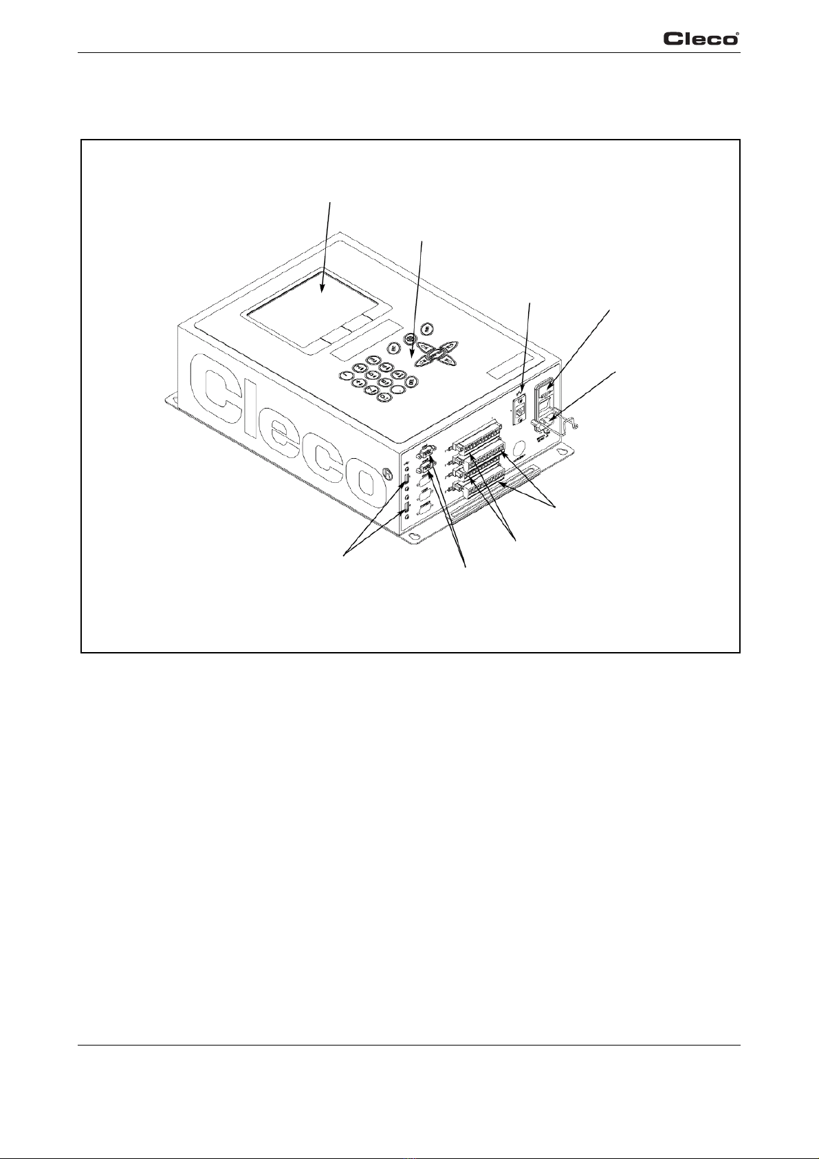
Attachment A.1
LCD display
USB Ports
Key pad
Ethernet Port
Power In
Serial Ports
a00729
I/O outputs
I/O inputs
Fuse holder
Fig. 1-3: Controller

en01c381.fm, 23.04.2009 P1934E/EN 2009-04 13
Getting started 1
1.8 System overview
Overview EC TMEC
Alternatives
Item Designation
1 TMEC-200 – Controller for electric nutrunner
2 Access point –
Order no. 543995 (NA)
Order no. 961323 (EU)
3 Tool series 47BAW…, 47BAX…, 47BAR…
4 Tool holder
Order no. 935290 – with IrDA interface, RS232 connection cable
Order no. 935395 – without IrDA interface, RS232 connection cable
5 Tool series 17BPW…, 17BPX…, 17BPR…
6 Tool holder
Order no. 935144 – with IrDA interface, RS232 connection cable
Order no. 935396 – without IrDA interface, RS232 connection cable
10 TMEB-COM – Computer with PC software
11 Base station
Order no. 961300 – 868 MHz (EU)

14 P1934E/EN 2009-04 en01c381.fm, 23.04.2009
Getting started
1

en02c381.fm, 23.04.2009 P1934E/EN 2009-04 15
Controller specifications 2
2 Controller specifications
2.1 Understanding the keypad
The following is a brief explanation of the keypad keys. You will need to become familiar with
these keys so you can smoothly program your unit.
7
1
654
2 3
Pos. Key Function
1ESC to leave Edit mode.
2Ship's wheel used at any time to return to the navigator menu.
3RUN used to return at any time to Run Screen.
4ENTER used to accept an answer/value on the LCD screen.
5Arrow keys used to move the orange highlight around the screen.
6DEL used to delete a numerical value on the LCD screen.
7Softkeys (F1-F4) used to select functions based on the screen displayed.

16 P1934E/EN 2009-04 en02c381.fm, 23.04.2009
Controller specifications
2
2.2 Technical data
2.2.1 Housing
The TMEC-200 housing is enclosed with no front door. The controller can be opened by remov-
ing from the wall and removing the back plate. All I/O connector are on the bottom of the enclo-
sure.
Model Weight Width Height Depth
lb kg in mm in mm in mm
TMEC-200 13 5,9 11 279,4 17 431,8 5127
2.2.2 Display
• Color LCD modules
• 640 x 480 resolution
• CCFT backlight
• Contrast and Brightness control
2.2.3 Keypad overlay
Key definitions
Key Description
0 – 9 Numbers 0 – 9
Letters A – Z Included on numeric buttons 2 through 9
(cell phone style)
.Decimal point
DEL Delete
ESC Escape
Navigator Menu
RUN Run Screen
Up Arrow
Down Arrow
Left Arrow
Right Arrow
ENTER Enter
Orange field 4 Softkeys

en02c381.fm, 23.04.2009 P1934E/EN 2009-04 17
Controller specifications 2
The alpha-numeric keys (2 – 9) are context sensitive: only numbers are available for fields that
require only numerical input, and alphabetical and numeric entries are possible for text fields.
In text fields the key scrolls through the letters and number with each successive press of the
key. For example, the <2abc> button in a numeric field will only provide the number 2.
In a text field, the 1st press will be "A" (capital), the 2nd press will toggle to "a" (lower case), the
3rd press toggles to "B", 4th press "b", 5th press "C", 6th press "c", 7th press "2", and then recy-
cles back to "A". Once you have toggled to the character required, move to another key to input
the next character.
2.2.4 CPU with PC 104
Minimum requirements
• Pentium 166 Mhz
• 32 MB DRAM
• 32 MB DiskonChip
• 2 serial ports
• 1 parallel port
• Ethernet 100-Base T
• PC Keyboard input
• PC/104 Bus
• Floppy interface
• LCD/Flat Panel controller
• 2 USB ports

18 P1934E/EN 2009-04 en02c381.fm, 23.04.2009
Controller specifications
2
Arcnet PC/104 board
• Arcnet communication
•4+24V inputs
•12+24V outputs
• 24-position keypad decoder
• Battery-Backed SRAM, 1 MB
External I/O PC/104 board
• 8 optically isolated inputs
• 8 relay outputs
2.2.5 AC power supply
90 – 264 VAC AC input power,
47 – 63 Hz single phase,
< 5 A at minimum input voltage.
2.2.6 Internal DC power supply
• Primary: 90 – 264 VAC, 47 – 63 Hz single phase
• Secondary: +5 VDC, 5 A; +12 VDC, 1 A; +24 VDC, 3 A; ±5% at all voltages
•65W capability without a fan
•MTBF-> 20,000 hours
2.2.7 Input / output connectors
Serial (2) 9-pin Male D-Shell
Inputs (+24 V) Phoenix MSTBV 2.5/12-GF-5.08 Order No. 1777170
Outputs Phoenix ICV 2.5/12-GF-5.08 Order No. 1825792
USB 2 each
Ethernet RJ45
AC Input Power Cold device plug

Serial
Pin # Description Value
1DCD -25V.. +25 V
2RxD -25V.. +25 V
3TxD -25V.. +25 V
4DTR -25V.. +25 V
5Signal Ground 0 V
6DSR -25V.. +25 V
7RTS -25V.. +25 V
8CTS -25V.. +25 V
9RI -25V.. +25 V
Parallel
Pin # Description Value
1Strobe 0.. +5 V
2Data 0 0.. +5 V
3Data 1 0.. +5 V
4Data 2 0.. +5 V
5Data 3 0.. +5 V
6Data 4 0.. +5 V
7Data 5 0.. +5 V
8Data 6 0.. +5 V
9Data 7 0.. +5 V
10 Acknowledgment 0.. +5 V
11 Busy 0.. +5 V
12 Paper Out 0.. +5 V
13 Select Out 0.. +5 V
14 Auto Feed 0.. +5 V
15 Error 0.. +5 V
16 Initialize 0.. +5 V
17 Select In 0.. +5 V
18 Signal Ground 0 V
19 Signal Ground 0 V
20 Signal Ground 0 V
21 Signal Ground 0 V
22 Signal Ground 0 V
23 Signal Ground 0 V
24 Signal Ground 0 V
25 Signal Ground 0 V
en02c381.fm, 23.04.2009 P1934E/EN 2009-04 19
Controller specifications 2

Keyboard
Pin # Description Value
1Data 0.. +5 V
2nc N/A
3Signal Ground 0 V
4Power supply 0.. +5 V
5Clock 0.. +5 V
Inputs
Pin # Description Value
1+24 V (Output) +24 VDC
2Input 0 0.. +24V
3Input 1 0.. +24V
4Input 2 0.. +24V
5Input 3 0.. +24V
6Input 4 0.. +24V
7Input 5 0.. +24V
8Input 6 0.. +24V
9Input 7 0.. +24V
10 Input Common (Input) 0 V
11 Signal Gnd (Output) 0 V
12 Spare N/A
20 P1934E/EN 2009-04 en02c381.fm, 23.04.2009
Controller specifications
2
For signal description please see chapter 3.4.2 Advanced Application Builder / Inputs – only for
TMEB-200 / TMEC, page 40.
Outputs
Pin # Description Value
1+24 V (Output) +24 VDC
2Output Common (Output) 0.. 30 V
3Output 0 0.. 30 V
4Output 1 0.. 30 V
5Output 2 0.. 30 V
6Output 3 0.. 30 V
7Output 4 0.. 30 V
8Output 5 0.. 30 V
9Output 6 0.. 30 V
10 Output 7 0.. 30 V
11 Signal Gnd (Output) 0 V
12 Spare N/A
For signal description please see chapter 3.4.3 Advanced Application Builder / Outputs – only for
TMEB-200 / TMEC, page 42.
Table of contents
Popular Industrial Electrical manuals by other brands

Eaton
Eaton M22 ADC Series Instruction leaflet

Max-Air Technology
Max-Air Technology Max Electric EFS 550 Series Installation, operation and maintenance instructions

Murata
Murata GRT21BR60J106KE01 Series Reference sheet

Hardinge
Hardinge GX Series Electrical Manual

ABB
ABB Three Phase Mechanical AutoLink instruction manual

Murata
Murata GRM033R61E102KA01 Series Reference sheet

Siemens
Siemens SIVACON 8PS BD2 Series installation instructions

Eaton
Eaton BZM1-XDV installation instructions

Murata
Murata GRM1555C1HR20BA01 Series Reference sheet

pemsa
pemsa rejibend 35 installation guide

Murata
Murata GRM1885C1H132JA01 Series Reference sheet

Murata
Murata GQM1875C2E1R1WB12 Series Reference sheet


