Rev: June 10, 2023 12:10 PM
Website
Max-Air Technology, Inc. • 114 Resource Drive • Wentzville, MO 63385 • United States of America
Tel
+1.636.272.4934
•
Toll
Free
888.842.9998
•
Fax
636.272.4937
•
www.maxairtech.com
•
[email protected]1
File Name: Max-Electric_IOM_EFS550_650-HVLV-MOD.pdf
Throughout the installation phases and operation of this equipment,
safety procedures take precedence over all other activities. As a minimum:
1. Read and follow all instructions in this IOM.
2. Before handling electrical connections, disconnect power feeds. There may be
multiple power feeds connected to this unit. Proceed carefully when opening the
cabinet cover.
3. Risk of electric shock! All wiring must be in accordance with applicable local
codes, regulations and the NEC. Be aware that there may be hazardous voltages
present which can shock, burn, or possibly cause permanent injury or even death.
This is a stored energy system. This device is designed to supply backup power
when mains power is lost or disconnected. Terminals are live whenever the
battery is connected.
Safety First!
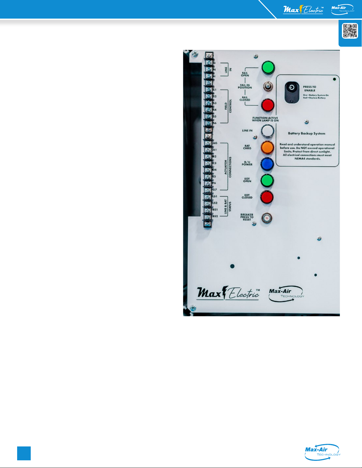
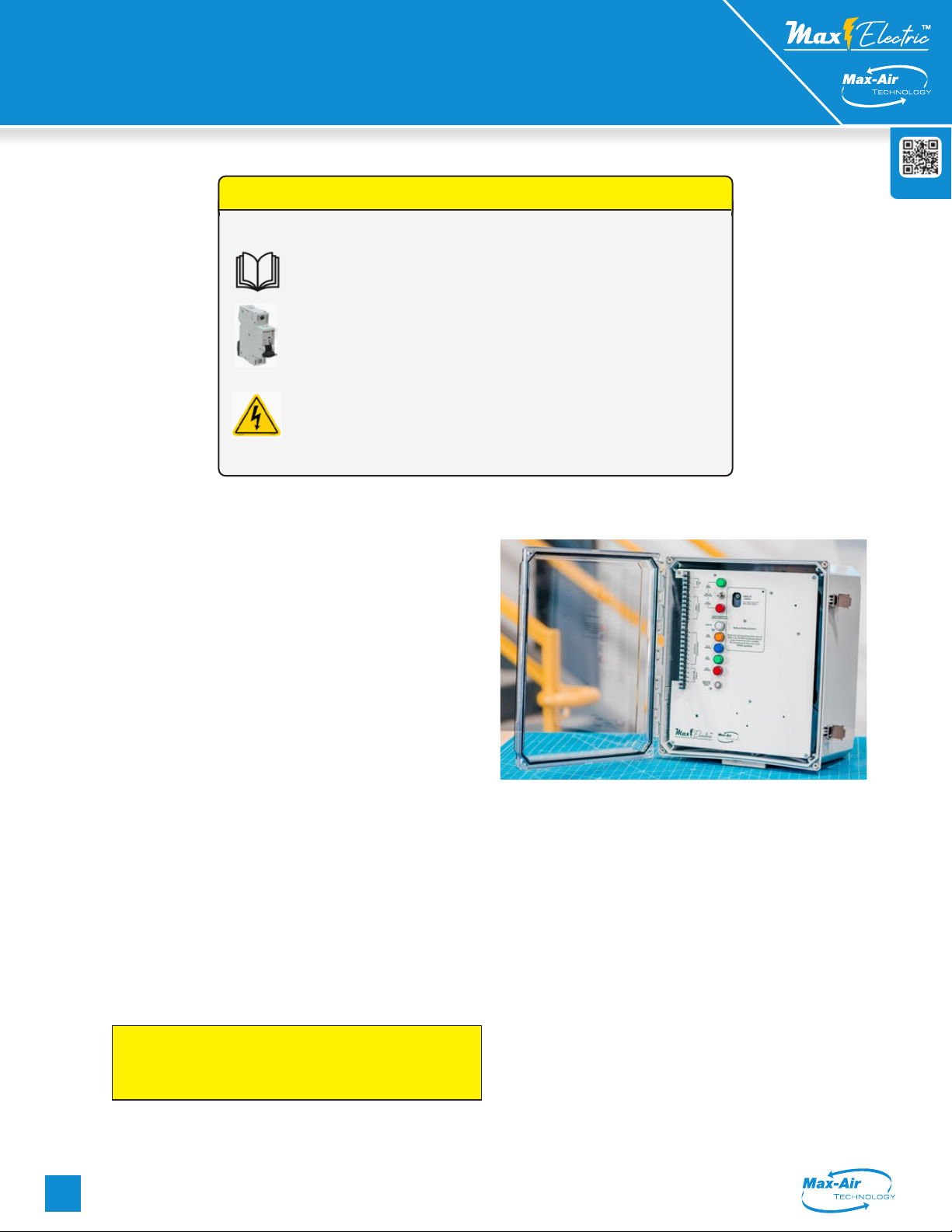
Handling & Storage:
This product contains a lead-acid battery storage system. It
is designed as a backup power supply for industrial electric
actuators. The enclosure is a weather-resistant NEMA4X
polycarbonate enclosure with a clear hinged door. Care must be
taken during shipping and handling to prevent damage to any
of the components or the enclosure. It contains logic control PC
boards, various discrete electronic components and electrical
storage devices, all of which are susceptible to damage from
high humidity environments. For this reason, this device must be
protected from direct contact with water and/or high humidity
storage environments.
Protect the device from physical damage while awaiting the
completion of installation processes.
Product shipping information:
The EFS system is packaged in two separate boxes inside one larger
shipping carton. This is done to prevent shipping damage to both the
polycarbonate enclosure as well as to sensitive components associated
with the heavier control panel and battery back up system.
1. BOX 1 contains the berglass enclosure. Do NOT use sharp
objects when opening the carton as you may damage the clear
lexan door attached to the enclosure cabinet.
2. BOX 2 contains the main face plate panel, battery system and
control electronics.
3. This unit is shipped with the battery system disconnected.
Follow the instructions below to correctly reconnect the battery
to the power unit. Failure to follow the connection sequence will
prevent the battery unit from starting.
4. Do NOT mount the panel in the cabinet until instructed to do so.
Installation:
1. Mount the cabinet either indoors or outdoors protected
from direct sunlight or other high heat sources. The cabinet
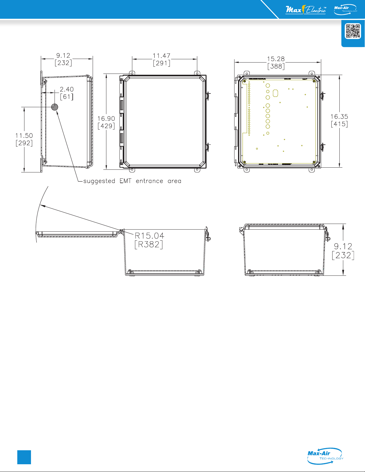
mounts with the latches to the RIGHT, and hinge to the LEFT.
The suggested EMT entry location is shown on page 18 in
the dimensional drawing. Make all conduit penetrations per
local code and perform all wire pulls prior to installing the
main control panel.
2. The enclosure must be mounted onto a stable, vibration-
free structure. The control panel is very heavy, and unstable
platforms my cause the panel to dislodge from the enclosure.
EFS550 Series
|
O / C
Installation, Operation and Maintenance Instructions
EFS 550 / 650 Series | Mod
Installation, Operation and Maintenance Instructions