manuals.online logo
Brands
  1. Home
  2. •
  3. Brands
  4. •
  5. Cleerline
  6. •
  7. Network Cables
  8. •
  9. Cleerline SSF User manual

Cleerline SSF User manual

1. Slide included and grommet strain relief boot
onto cable.
2. Measure the tubing down the length of the
cable. Place a mark 6”/15 cm from the end of
the tubing.
3. Using the fiber strippers’ 2.0 mm opening,
remove the jacket at marking so that the
exposed fiber is equal to the breakout tubing
and assembly plus 6” or 15 cm.
4. Working on a flat surface with an edge, tape
down the cable.
5. Separate aramid yarns from fiber. Cut yarns
approximately 6”/15 cm from end of jacket.
6. Slide housing over exposed fibers. For six
fiber kit, place fibers 1-6 all on one side of
housing. If installing 12 fiber kit place fibers
7-12 on other side.
Cleerline SSF TM 3.0 mm Breakout Kit
This guide describes spider breakout kit installation on 250 µm optical fiber. Installation factors such as available cable slack,
location of the termination hardware and the question of build tube slack storage as opposed to cable slack can dictate when and
where you choose to mount the cable end and assemble your breakout kit.
Termination With:
SSF TM Micro Distribution 250 µm Fibers
CLEERLINE
TECHNOLOGY GROUP
TM
cleerlinefiber.com
Revise #1.5
Each Breakout Kit Contains
a. Insert block furcation tube assembly
(1 for 6 fiber, 2 for 12 fiber)
b. Outer Shell
c. Housing
d. Grommet Strain Relief Boot
e. Nut
f. Screw (x2)
g. Plug (not used in these instructions)
h. 6 Fiber Bushing (not used in these instructions)
i. 12 fiber Bushing (not used in these instructions)
Required Tools
a. Fiber Optic Strippers
b. Aramid Shears
c. Pliers
d. Ruler
e. Tape
f. Marker
Cleerline SSF TM 3.0 mm Breakout Kit
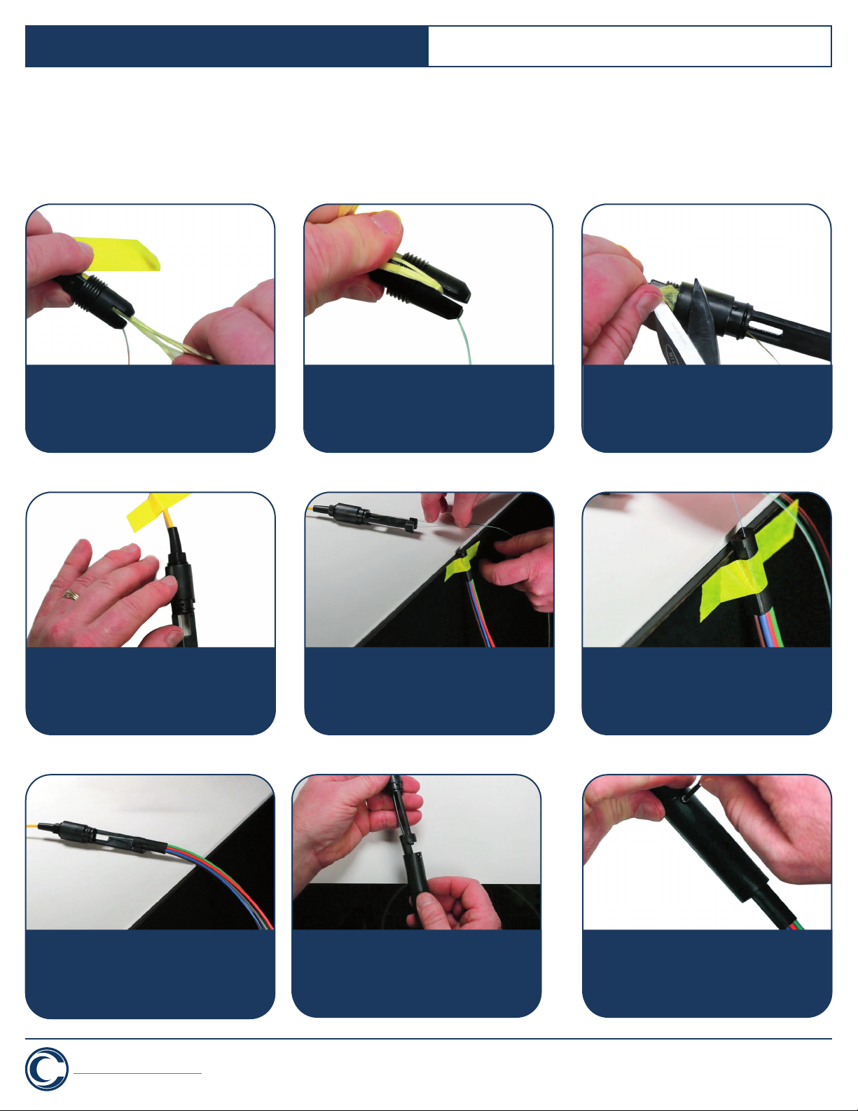
10. Working on flat surface with an edge, tape
down housing assembly so end of the housing
is 2”/ 5 cm from edge. Drape fibers over edge
so fibers 1-6 are positioned upwards.
11. Tape insert block section of the furcation tube
assembly to edge of the surface so tubes hang
down to floor. Untangle fibers so each can be
separated back to the point where it exits the
housing assembly.
12. Insert fiber 1 through matching colored furcation
tube block until fiber exits far end of the tubing.
Ensure fibers are not twisted. Repeat process
for fibers 2-6. For 12 fiber kit, remove tape from
housing, rotate housing 180° and tape down.
13. Remove block furcation tube assembly from work
surface. Slide assembly toward housing and insert
block into place on housing. For 12 fiber kit, tape
block tube assembly for fibers 7-12 to edge of
surface. Insert fibers and insert block into housing.
14. With notches forward toward furcation tubing,
slide outer shell over tubing and onto housing. Align
notches and screw holes in housing and shell.
15. Insert two screws and tighten.
CLEERLINE
TECHNOLOGY GROUP
TM
cleerlinefiber.com
Revise #1.5
Termination With:
SSF TM Micro Distribution 250 µm Fibers
7. Untape cable. Slide grommet strain relief
and nut forward on the jacket and position
end of cable jacket even with the slits in the
grommet strain boot.
8. Position aramid yarns through one of slits in
boot. Hold yarns along cable jacket.
9. Bring housing forward and tighten one full
turn to lock in the yarns. Cut yarns closely
to housing. Tighten housing until secure.

Popular Network Cables manuals by other brands

Tripp Lite N201-020-RD Specification sheet

Tripp Lite

Tripp Lite N201-020-RD Specification sheet

Tripp Lite N002-007-YW Specification sheet

Tripp Lite

Tripp Lite N002-007-YW Specification sheet

Tripp Lite N002-002-BL Specification sheet

Tripp Lite

Tripp Lite N002-002-BL Specification sheet

Tripp Lite N304-010 Specification sheet

Tripp Lite

Tripp Lite N304-010 Specification sheet

Tripp Lite N312-05M Specification sheet

Tripp Lite

Tripp Lite N312-05M Specification sheet

Tripp Lite N308-05M Specification sheet

Tripp Lite

Tripp Lite N308-05M Specification sheet

Tripp Lite P753-010 Specification sheet

Tripp Lite

Tripp Lite P753-010 Specification sheet

Tripp Lite N316-30M Specification sheet

Tripp Lite

Tripp Lite N316-30M Specification sheet

Lindy 42617 user manual

Lindy

Lindy 42617 user manual

manuals.online logo
manuals.online logoBrands
  • About & Mission
  • Contact us
  • Privacy Policy
  • Terms and Conditions

Copyright 2025 Manuals.Online. All Rights Reserved.