CLEVELINGS BLUEBOX 1.0 User manual


Instrukcja
1
Contents
1. GENERAL INFORMATION ........................................................................................................................................................ 2
1.1 Signs used in the instruction........................................................................................................................ 2
1.2 Use............................................................................................................................................................... 2
2. SAFETY.................................................................................................................................................................................... 3
2.1 General safety systems................................................................................................................................ 3
2.2 Workplace safety......................................................................................................................................... 3
2.3 Electrical safety ........................................................................................................................................... 4
2.4 Personnel safety .......................................................................................................................................... 4
2.5 Use............................................................................................................................................................... 4
2.6 Possible danger sources .............................................................................................................................. 4
2.7 Power supply ............................................................................................................................................... 5
2.8 Power generators........................................................................................................................................ 5
2.9 Extension cords............................................................................................................................................ 6
2.10 Servicing ...................................................................................................................................................... 6
3. TECHNICAL SPECIFICATION ..................................................................................................................................................... 6
3.1 Construction ................................................................................................................................................ 7
3.1.1 Construction (outside) .........................................................................................................................7
3.1.2 Front panel layout................................................................................................................................8
3.1.3 Connection adaptors............................................................................................................................8
3.1.4 Identification plates .............................................................................................................................9
3.1.5 Barcode scanner...................................................................................................................................9
3.1.6 Acoustic signal....................................................................................................................................10
3.1.7 Keypad................................................................................................................................................10
3.2 Start-up...................................................................................................................................................... 10
3.2.1 Transport, packing and storage .........................................................................................................10
3.2.2. Operating personnel..........................................................................................................................10
3.2.3. Start-up procedure.............................................................................................................................10
4. WELDING PROCESS............................................................................................................................................................... 11
5. OPERATING INSTRUCTIONS .................................................................................................................................................. 12
5.1 Starting messages ..................................................................................................................................... 12
5.2 Welding......................................................................................................................................................13
5.3 Settings...................................................................................................................................................... 15
6. TROUBLESHOOTING ............................................................................................................................................................. 17
7. MAINTENANCE ..................................................................................................................................................................... 19
8. FINAL REMARKS.................................................................................................................................................................... 20
9. FORBIDDEN ACTIONS............................................................................................................................................................ 20
10. FIREFIGHTING INSTRUCTIONS............................................................................................................................................. 20

2
1. GENERAL INFORMATION
NOTE
Before proceeding to work with the device make sure to read closely this user manual, which constitutes
integral part of the device. The instruction shall be used before work, during and after the launch and
anytime it’s deemed to be necessary.
Following above instructions is the only way to achieve three main objectives of this instruction manual i.e.:
•Optimization of work effects and performance of the device
•Protection against injuries
•Protection against damage and destruction of the device
1.1 Signs used in the instruction
Present instruction include following safety signs and warnings.
Symbol
Description
WARNING
This symbol refers to a direct threat to the life or health of a person.
Ignoring the warning results in serious injuries and may even have fatal consequences.
CAUTION
This symbol provides important information referring to proper operating of the device. Ignoring this
message might lead to a malfunction, damaging the material or damages done to the environment.
INFORMATION
This symbol provides instructions and valuable information. Such information will help you to use the
machine functions in optimal way.
1.2 Use
Electrofusion welding unit serves for joining of plastic pipes and fittings. Using the device for purposes other than the ones
described in this manual is forbidden and can be dangerous to the operator and assisting personnel or can lead to damaging the
device or other equipment located in the area.
In order to use the device accordingly make sure to follow:
•all recommendations included in this user manual
•general and detailed guidelines on electrofusion fittings
•applicable health and safety regulations, environmental protection regulations, legal regulations and all standards, laws
and directives in force in a given country
Electrofusion welding consist in joining two (PP, PE) pipe ends with the use of electrofusion fitting like e.g. couplers, tees,
reductions, saddles, etc. During welding process the device provides electric energy of strictly defined parameters to the resistance
wire located on the inner surface of the fitting. Electric energy is transformed into heat causing the polyethylene on the fitting and
fitting to melt and bond by filling up the space between both elements. After cooling and crystallization of polyethylene, the
connection is durable, firm and reliable.
Electrofusion welding process is performed correctly only if device applied for this purpose allows for full control of process
parameters such as:
•welding voltage
•duration of subsequent stages of welding process

Instrukcja
3
Stage of
process
Description
I
Preparation of pipes
II
Installation of pipe-fitting assembly in aligning tool
III
Welding
IV
Cooling
2. SAFETY
2.1 General safety systems
WARNING
Every operator is obliged to read the user manual before
proceeding to work with the device. During work operator shall use
direct protection measures required in the workplace.
Electrofusion welding unit is designed accordingly with current regulations and shall be used exclusively for welding pipes and
fittings made of polyolefins. Electrofusion welding process does not pose any danger to the operator provided that the safety rules
are followed. However, using the device by unqualified personnel or not following the safety rules could lead to injuries.
All people not involved into the process shall make sure to maintain safe distance while the device is working.
Improper handling or improper use of the device could lead to:
•Threat to the health and life of the operator
•Damage to the electrofusion welding unit
•Decrease in work efficiency of the welding unit
•Obtaining low quality connections
2.2 Workplace safety
•Workplace shall be kept clean and properly lit. Disorder and improper lighting in the workplace can lead to accidents.
•Do not use power tools in the explosive zone areas with flammable gases, liquids or dusts. Power tools might generate
sparks which could ignite them.
•Do not allow children of any 3rd parties in the working area. Their presence could distract the operator which could lead
to losing control over the device.
WARNING
Device shall be used only by properly trained personnel with suitable qualifications. Using the device against
its original purpose is forbidden and might be dangerous to the operator and assisting personnel and could
lead to damaging the device or other equipment in the closest area.
CAUTION
Each unauthorized use of the device, use against its purpose or any interference into its construction will
result with immediate loss of warranty.

4
2.3 Electrical safety
•Power supply plug must fit the socket perfectly and cannot be modified in any way. Power tool that require protective
grounding cannot be powered through extension cords. Use of unmodified plugs and proper sockets significantly reduce
the risk of sustaining an electric shock.
•Avoid touching non-grounded elements, e.g. pipes. Grounding one’s body increases the danger of sustaining an electric
shock.
•Do not expose power tools to moisture or rain. The penetration of water inside the power tool increases the risk of
sustaining an electric shock.
•Power supply cable does not serve for: transport purposes, hanging or lifting the device, pulling the plug out of socket.
Protect the power supply cable against high temperatures, sharp edges, oils and moving elements. Damaged or entangled
cable increases the risk of sustaining an electric shock.
•During work on the outside, when it’s necessary to use extension cables make sure to use extension cables intended for
outside use. Using such type of extension cable decreases the risk of electric shock.
•If you are working in high humidity conditions use a circuit breaker. The use of a current protection switch reduces the risk
of electric shock.
2.4 Personnel safety
•Be attentive, pay attention to performed actions, take reasonable care while working with power tools. Do not use power
tools if you are tired or under the influence of drugs, alcohol or medication.
•Wear personal protective equipment and always safety goggles. The use of personal protective equipment such as non-
slip footwear, a protective helmet or hearing protection, depending on the power tool used, reduces the risk of injury.
•Eliminate the possibility of accidental start of the device. Before connecting to the power outlet and before touching or
moving the device make sure it’s turned off. Moving an electrical device with your finger on the switch or attempting to
connect to a power outlet while the equipment is turned on may lead to an accident.
•Avoid unnatural body positions during work. Ensure a safe standing position and keep your balance at all times. This will
allow you to better control the power tool in unexpected situations.
2.5 Use
•Do not overload the device. For each work use suitably selected tools. Properly selected tools allow for easier and more
confident work in desired power range.
•Do not use power tools with damaged power switch. Device that doesn’t allow for emergency shutdown at any given
moment poses a danger and shall get repaired.
•Before preparing the device for work, replacing accessories or putting the device back make sure to remove the plug
from power outlet. These safety precautions prevent from accidental start of the device.
•Unused power tools shall be stored away from the reach of children. Do not allow people unfamiliar with the device, or
this instruction manual, to operate it. Power tools in the hands of inexperienced personnel could be dangerous.
•Take care of the power tools. Damaged parts shall be replaced by authorized service centers. Many accidents are
attributed to improper maintenance.
•Use the device in accordance with these instructions. The operating conditions and the type of operation to be carried
out must be taken into account. Using power tools for other purposes than intended may lead to dangerous situations.
2.6 Possible danger sources
Electrofusion welding unit is an electrical device and thus it’s forbidden to:
•leave the device unattended
•use damaged device (casing, cables, extensions)
WARNING
Danger of sustaining an electric shock from elements under voltage. Danger to health and life.

Instrukcja
5
•service the device that is under voltage
•work with the device on voltage different that intended
•remove safety equipment during welding process
Electrofusion unit shall be used in accordance with general safety rules. There should be proper ventilation ensured in the place
of work and enough space for operation to be carried in safe manner. If the work is carried outside suitable measures shall be
taken to protect the device against weather conditions. It’s forbidden to use the device in the proximity of flammable substances,
explosive zones, excessively hot or cold conditions or in too high humidity or with high level of dust.
It’s forbidden to clean the device with the use of solvents or other aggressive substances which could permanently damage the
external surface or damage the plastic elements. Only trained personnel can use the device. All repairs shall be performed by
qualified personnel.
2.7 Power supply
1st generation electrofusion welding units are adapted to work with power supply AC 230V (+/-15%), 50Hz (+/-10%) from mains
or power generator. In case of working in outdoors conditions (construction site) electric sockets should ensure stable
parameters of power supply. Power generator or mains to which the device is connected should be equipped (depending on
model) with (delay) safety fuses 16A or 20A.
2.8 Power generators
Before connecting the device to power generator make sure it’s recommended for work on the building site. Follow the user
manual delivered with the generator. Connect the electrofusion unit to the generator at least 1 minute after starting the
generator. Do not connect other power tools to the generator during welding process.
After finishing the welding process firstly turn off the welding unit main switch, then unplug the device from generator and lastly
turn off the power generator. Following this sequence will protect the welding unit from damaging it with voltage peaks which
appear during start-up and shut down of power generator.
Required nominal power of the power generator depends on:
•fitting resistance and welding voltage
•outside conditions
•connection
WARNING
Danger of fire or explosion in case of contact with flammable materials.
INFORMATION
Before connecting the device to power outlet make sure the power supply parameters are within the range
of work of the device –195 do 265 V!
WARNING
230V power supply should have grounding wire, residual current circuit breaker and overcurrent protection. It’s
forbidden to connect the device to power outlets without neutral wire and grounding pin.

6
2.9 Extension cords
Poniższa tabela przedstawia zmianę wymaganego przekroju przedłużacza w zależności od jego długości.
Length
Cross-section
up to 50 m
2,5mm2
up to 100m
4 mm2
2.10 Servicing
3. TECHNICAL SPECIFICATION
*only when full cooling times are maintained
INFORMATION
Different types of power generators often show different regulating characteristics. As a result selecting the power
generator basing solely on nominal power might not be effective. When in doubt whether given power generator
is suitable for work with the electrofusion unit contact authorized service department.
INFORMATION
In order to minimize the risk of overheating the extension cord, make sure to unfold it!
WARNING
Repairs of power tools shall be performed by professionals and only with the use of original spare parts. This allows
to keep the devices safe in use.
Technical parameters
Type:
BLUEBOX 1.0
Approximate diameter range:
~160mm
Power supply [V]:
230
Input voltage [V]:
195 –255
Frequency range [Hz]
45 –55
Max. welding current [A]:
60
Max. fitting power [W]:
1450
Weight [kg]:
13
Protection class:
IP-54
Power supply cable [m]:
3
Welding cables [m]:
3
Dimensions [mm]:
390 x 240 x 160
Voltage regulation range [V]:
8 –44
Volt. regulation step of change [V]:
0,1
Welding time step of change [s]:
1
Cooling time step of change [min]:
1
Working temperature [°C]:
- 5 to + 40
Recommended power generator
[kW]:
3
Welding data registration and
traceability:
-
Memory capacity:
-
Instrukcja
7
3.1 Construction
Electrofusion welding units BLUEBOX 1.0 are equipped with ABS-made casing permanently embedded in steel transport box.. CPU
board, power board, transformer and display are all mounted inside the casing. CPU board is responsible for controlling the
functions of the device by measuring the voltage and current and controls the duration of subsequent stages of welding process.
Device is equipped with outside temperature sensor (located on output cables) and sensor of temperature of transformer which
control its temperature and prevents the device from overheating.
Basic elements of electrofusion unit and its control panel are shown below.
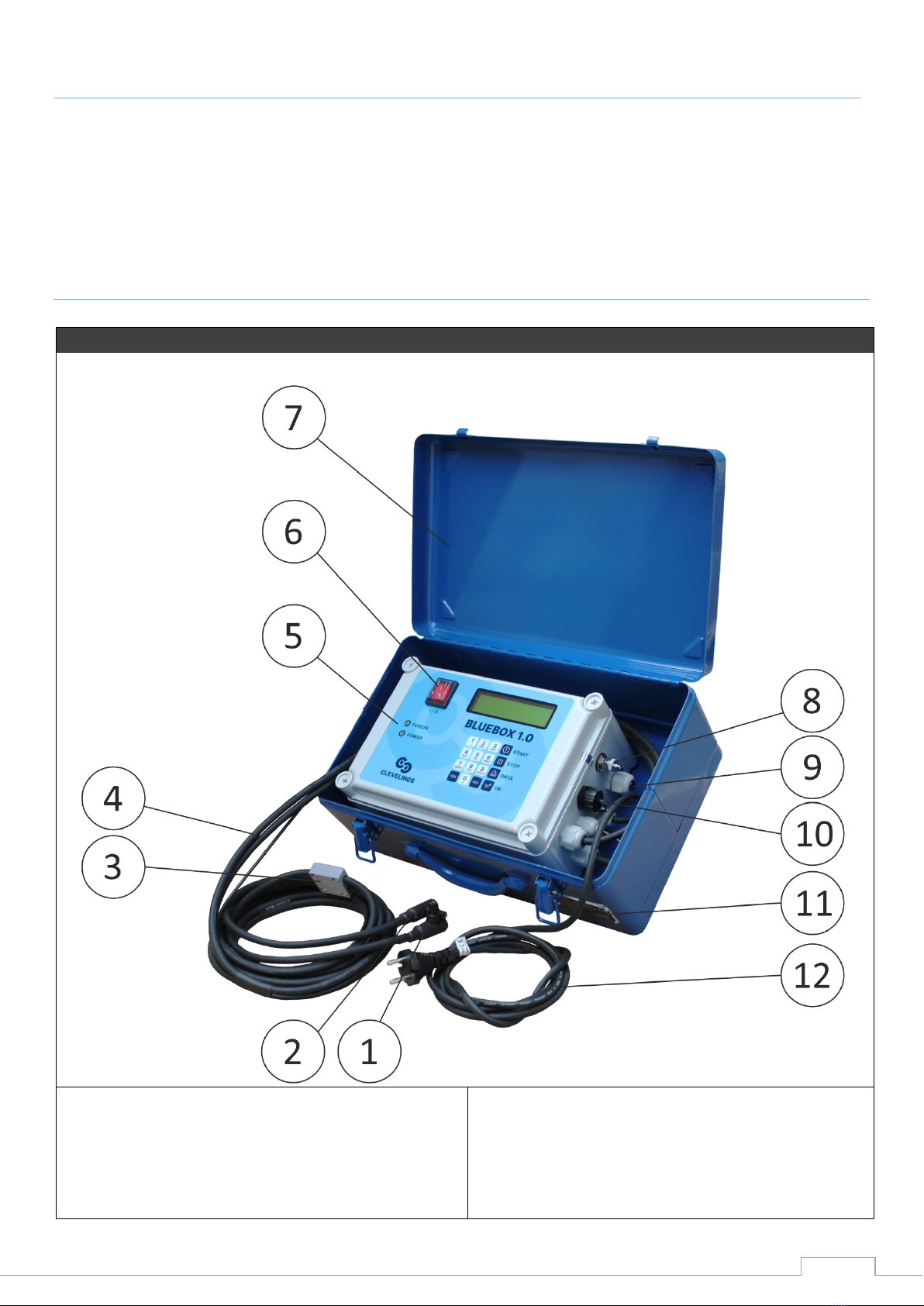
3.1.1 Construction (outside)
BLUEBOX 1.0
1. Adaptor
2. Adaptor connector
3. Outside temperature sensor
4. Output cables
5. Control panel
6. Main power switch
7. Metal transport box
8. M12 port for connectin the barcode scanner / printer
9. Acoustic signal
10. USB-B port (for communicaton with PC)
11. Identification plate
12. Power supply cable
8
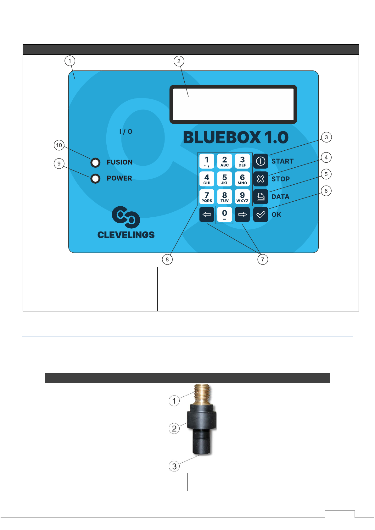
3.1.2 Front panel layout
Control panel
1. Control panel sticker
2. Display
3. START button
4. STOP button
5. PRINT button
6. CONFIRM button
7. Navigation button
8. Alphanumeric keypad
9. Power supply diode
10. ‘Welding in progress’ diode
3.1.3 Connection adaptors
Electrofusion welding units are equipped with two output cables ended with threaded connectors on which adaptors are to be
mounted. In standard each device is delivered with set of two adaptors ø4 and two adaptors ø4,7.
Elecrofusion adapters
1. M8 thread
2. Adaptor housing
3. Adaptor socket

Instrukcja
9
3.1.4 Identification plates
Identification plate includes technical characteristics of given model and unique serial number of the device. The plate is attached
to the front part of metal transport case in models BLUEBOX 1.0.
3.1.5 Barcode scanner
Barcode scanner constitutes part of additional equipment options. It’s connected to the welding unit via M12 port. Barcode
scanner uses a laser beam to scan and decode the information contained in the barcode. Barcode scanner is activated when device
is in main menu or in barcode scanner mode. Just point the scanner at the barcode and press the read button. The barcode is
scanned by a red laser beam that must pass through the entire barcode, perpendicular to the barcode line, possibly through the
center of it. The barcode will not be read correctly if the red light beam does not pass through the entire barcode. Optimum
reading results are obtained when the scanner is placed in close proximity to the barcode.
Barcode scanner
Incorrectly printed or slightly damaged barcodes can be read by placing the scanner directly over the barcode, and then, with
the read button pressed, slide the scanner over the barcode. When the barcode is correctly read, the device will emit a sound
signal and the screen will display information about the decoded welding parameters.
INFORMATION
In order to allow for easier identification of adaptor size, adaptors 4,7mm are market with a groove on its housing.
Adaptors 4mm have plain housing with no marks.
INFORMATION
Before each welding process make sure to check the correctness of montage of adaptors on output cables.
Pay special attention on choosing the right adaptors in relation to the pins located on the fitting. In case wrong
adaptors are used it might happen that welding process will not start, will get aborted or will be carried in incorrect
way.

10
3.1.6 Acoustic signal
1st generation electrofusion welding units use acoustic signal as a confirmation of certain actions performed by the operator.
These signals serve as a confirmation of correctly scanned barcode, finishing the welding process or error signalization.
3.1.7 Keypad
1st generation electrofusion welding units are equipped with keypad allowing to control the device, the keypad consists of
following elements:
Buttons 1-9 serve for inserting information about welding parameters, or editing the operator/site names
Arrow buttons –allow to navigate through the menu
START button –start welding process
STOP –stop welding process or return to previous screen
PRINT –start printing the protocol with the use of thermic printer or edit the name of operator/site (option available only in
units with memory)
3.2 Start-up
3.2.1 Transport, packing and storage
Electrofusion welding units, depending on the model, are originally packaged in cartoon or wooden box. The box is suitably
marked to indicate the correct position for transport and storage.
Electrofusion welding unit shall be kept in horizontal position in well air-conditioned spaces, protected against inadequate
weather conditions and meeting the firefighting requirements. Device shall be stored in temperature -10˚C to +55˚C and air
humidity shall not exceed 95%.
3.2.2. Operating personnel
Electrofusion welding unit should be operated by at least one operator with actual certificate of qualification allowing for joining
PE pipes with electrofusion welding method, proper training and being aware that improper steering could, in extreme cases, lead
to injury or even death of bystanders.
3.2.3. Start-up procedure
1. Make sure that power supply cable is disconnected from power outlet and the main switch is in “0” OFF position.
2. Check the overall condition of the device and electric cables
3. Ensure 230V, 50Hz stable power supply source –from the mains or from power generator of suitable power (detailed
info on p. 8)
4. Install suitable adaptors on the output cables
5. Set the welding unit in the welding area
INFORMATION
Protect the tip of the reader and the scanner window from damage and contamination! The state of the scanner
window directly affects the operation of the scanner.
CAUTION
Remember to protect the device against exposure to water (rain, flood), low temperatures and high humidity
during work, transport and storage. It’s advised to transport the device with ‘covered’ means of transport.
Instrukcja
11
6. Connect the power supply cable to the AC power outlet.
7. Turn on the device by turning the main switch to position “1” ON
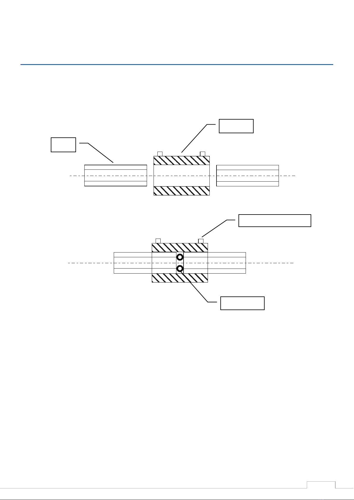
4. WELDING PROCESS
The electrofusion welding process is based on the use of heat, which is released when the current flows through the resistance
wire to heat the inner surface of the fitting and the outer surface of the pipe. The following picture shows how such connection
is formed.
Electrofusion welding process shall be carried accordingly to below general instructions and specific recommendations provided
by the fitting manufacturer:
1. Prepare the welding area
2. Clean the pipe ends
3. Cut the end of the pipe perpendicular to its axis
4. If the pipe isn’t round use special re-rounding tool
5. Verify if the fitting parameters match the pipe (diameter and SDR)
6. Mark the pipe insertion depth, or in case of saddles - the scraping area, with a marker.
7. Scrape the layer of 0,1-0,2 mm until the marker traces are no longer visible. It’s recommended to scrape even further
beyond marked area so that there is no doubt about the operation. Scraping marks should be visible on both sides of
welded fitting, or around the saddle.
8. Verify the correctness of scraping (removing oxidized layer of PE)
9. Clean the pipe inner and outer surface and inner surface of the fitting with suitable cleaning agent e.g. isoprophyl alcohol
soaked in absorbent, lint-free, non-pigmented material.
10. Mark the pipe insertion depth once again
11. Insert the pipes into the fitting and verify the insertion depth. All elements must be dry.
12. Fix the assembly in an aligner to ensure firm holding, in case of saddles –mount them accordingly to the instructions of
manufacturer.
spacer
pipe
Connection pin
fitting
12
13. Make sure if the welding unit has CE marking, valid calibration certificate and verify if the power supply source provides
correct parameters.
14. Connect the output cables to the fitting
15. Make sure the electrofusion adaptors match the fitting’s pins
16. If the device is equipped with additional options such as barcode scanner or thermal printer make sure to connect them
before turning on the welding unit.
17. Turn on the electrofusion welding unit
18. Adjust the welding parameters accordingly to the data provided on the fitting
19. Launch the welding process
20. Make sure that the process went smooth without any interruptions (no warning messages displayed)
21. Leave the assembly inside the aligner for the time of 1,5e [min] (e- pipe wall thickness)
22. Once the process is finished turn off the welding unit and pull out the output cables.
23. Mark the pipe with joint number, date of welding, and number of welder’s qualification certificate
24. Enter the parameters of performed joint onto the welding protocol if the machine has no internal memory storage.
5. OPERATING INSTRUCTIONS
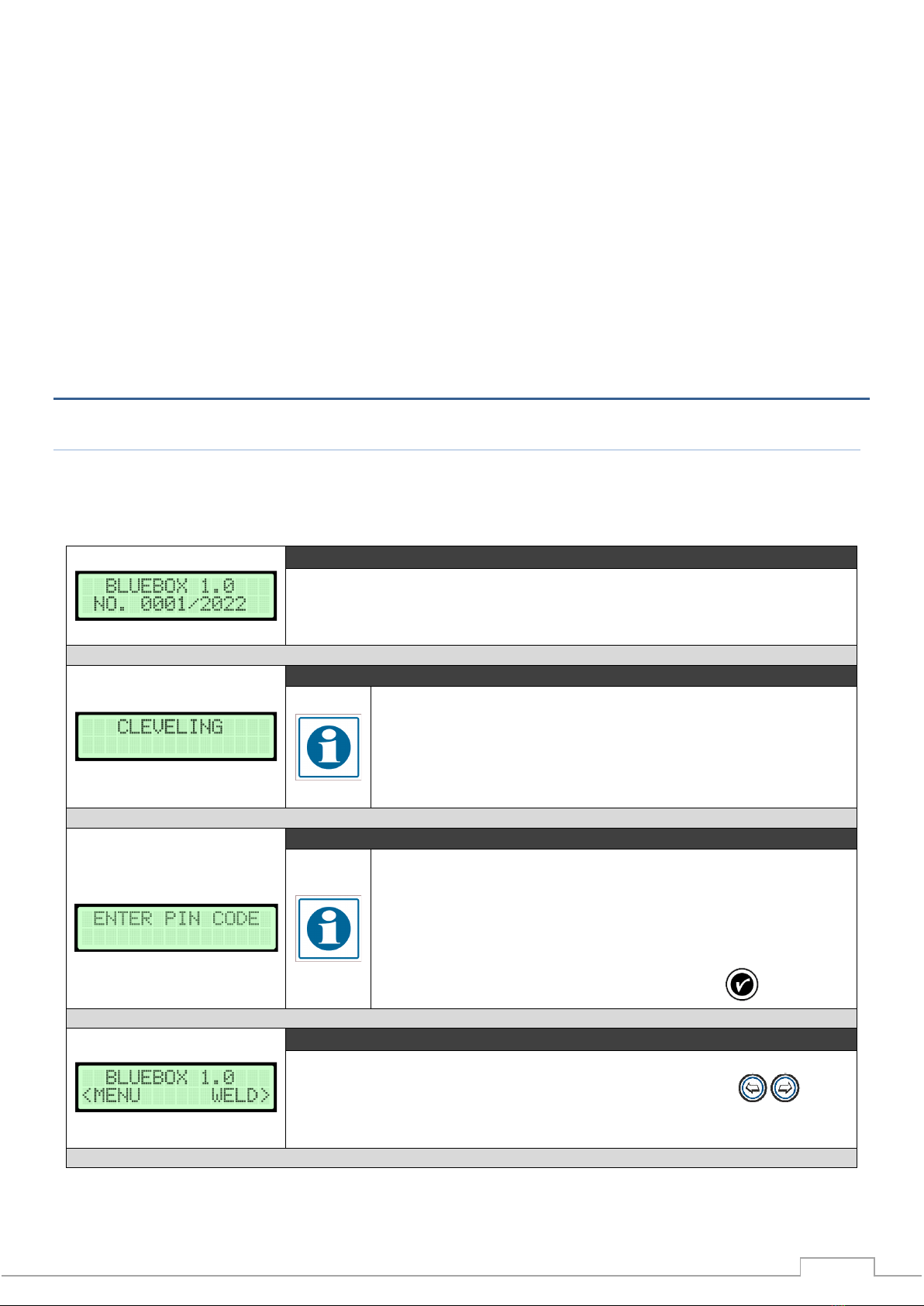
5.1 Starting messages
Turn the main switch to position ”1” ON. If the power supply voltage fits within required range device will start and be ready for
work.
LAUNCH SCREEN
On the screen are displayed following information: device type (model) and its serial
number
OWNER INFO
INFORMATION
Changing the owner's name is possible from the level welding
machine settings. Detailed description in the further part of the
manual.
PIN REQUEST
INFORMATION
If the PIN request function is turned on you will need to enter the PIN code
before accessing the main menu. PIN code is located on the warranty card
delivered together with the device. User cannot change the PIN code. Pin
code request can be turned off from the menu level.
In order to enter the code use keypad and then press to confirm.
MAIN SCREEN
Once the device is turned on it will display the main menu screen. Use
buttons to choose between MENU and WELD functions.

Instrukcja
13
5.2 Welding
WORK MODES
Electrofusion welder allows for work in four modes, three of which are operated manually
and these are: ‘manual’, ‘manual barcode’ and ‘as previously’. Barcode scanner is available
only for operators that are equipped with barcode scanner.
Use buttons to choose desired work mode and press to confirm.
MANUAL MODE
In manual mode operator has to enter all relevant parameters of welding process: welding
voltage, welding time, and cooling time. The parameters shall be taken directly from
electrofusion fitting or from special card provided by the manufacturer.
INFORMATION
When entering the heating time make sure to correct this value with
consideration to outside temperature. Outside temperature is indicated
on the screen as ‘To’.
To enter required information use buttons and alphanumeric keypad 0-9. Using
the arrows choose the character you wish to edit (currently edited character will be
highlighted), and then edit the value accordingly. Press to confirm. In order to return
to previous screen press .
SCANNER MODE
INFORMATION
Scanning the barcode can be done from scanner work mode level as well as
directly from the main menu screen.
In order to scan the barcode correctly direct the laser beam toward the barcode (from
suitable distance) and press the button located on the scanner. If the action is performed
correctly device will signalize it with short acoustic signal and proceed to the next step.
INFORMATION
Laser beam must cover entire length of the barcode.

14
INFORMATION
It’s advised to adjust the welding parameters through barcode scanner or by
entering the barcode manually. Both methods speed up the welding process
and eliminate the possibility of human error and automatically adjust the
heating time depending on the outside temperature.
INFORMATION
If there is no information in the barcode about cooling time, second fitting
diameter or fitting type, device will display a message asking to fill these
information manually.
BARCODE MANUAL
In manual barcode mode operator can enter the numerical code located underneath the
barcode manually (in case the scanner is damaged or there isn’t one). Enter the code using
alphanumeric keypad and confirm with .
AS PREVIOUSLY
Last work mode allows the operator to reuse the welding parameters from last correctly
performed weld. Choosing this work mode will allow you to skip entering the welding
parameters and automatically proceed to the next step.
POWER SOURCE
Before beginning the welding process operator has to select the power source to which
the machine is connected.
INFORMATION
Selection of power source is related with control mode that is used during
welding process (see page 21) and choosing wrong type of power source
might affect the welding process.
SUMMARY AND ADDITIONAL INFORMATION
Once the welding parameters are entered device will ask if an aligner is being applied for
the process.
Next, device will proceed to summary screen showing all previously entered parameters.
Press START to begin the welding process
WARNING
Operator should verify if entered parameters are correct. Starting the welding
process using inadequate parameters could pose a direct threat to one’s
health and life. Welding process can be aborted at any given moment by
pressing STOP button or turning it off with main power switch. If the welding
process gets aborted with STOP button such information will be saved in the
welding protocol, whereas when the process is aborted by turning off the
device no information will be saved in the memory.

Instrukcja
15
FITTING TEST
Before starting the welding process the welding unit will perform a short test of connected
fitting to confirm that the right type of fitting is connected. During the test device
measures the fitting resistance and compares it with the resistance encoded in the
barcode.
In case no discrepancies have been detected device will proceed and begin the welding
process. If however device detects discrepancies between the resistance encoded in the
barcode and the actual measured value device will display an error message. Because the
resistance might change depending on outside conditions error message doesn’t
necessarily mean there is a problem, especially in case of smaller diameter fittings. If the
operator is certain that the welding parameters are correct he can force the welding
process by skipping/ignoring the error messages and continuing the work.
INFORMATION
Fitting test will not be carried in three cases:
•Welding parameters were set manually
•The energy delivered to the fitting during the test might damage the fitting
(applies mostly to small diameter fittings e.g. 20, 25mm which have short
heating time and low welding voltage)
•Resistance encoded in the barcode is saved as non-controlled parameter
(resistance equal to 0 Ohm)
Last message before actual welding process the device counts down the time to starting
the welding process. During this time the operator has the possibility to abort the process
by pressing the button.
When the process is complete, the welding machine will automatically start the
programmed cooling time. For welding machines with parameter recording, the
interruption of this process by pressing a button will be recorded in the protocol.
5.3 SETTINGS
SETTINGS
User can modify some of the basic settings in the SETTINGS menu.
DISPLAY
In display settings user can turn on/off the backlight by pressing one of buttons
while in BACKLIGHT menu. Press to proceed to brightness settings. In order to adjust
the brightness use buttons.

16
DATE AND TIME
Next, are the date and time settings. In order to adjust the values use alphanumeric
keypad. Currently edited character is marked by flashing rectangle. Using arrow buttons
choose the character you wish to edit and then, using alphanumeric buttons, edit the
value. Press to confirm. In order to return to previous screen press
OWNER
Changing the owner info can be done in two ways –using the NT Connection software or
directly on the device. In case of the second method use alphanumeric keypad to enter
desired information. Currently edited character is marked by flashing rectangle. Using
arrow buttons choose the character you wish to edit and then, using alphanumeric
buttons, edit the value. Press to confirm. In order to return to previous screen press
.
CALIBRATION CHECK
The user can also check the calibration validity date. Additionally device will display a
reminder few days before expiration of calibration certificate.
INFORMATION
30 days before the calibration ends within each start-up device will display a
message that calibration will soon expire. Once the calibration expires device
will show message: calibration expired. Devices with expired calibration
aren’t automatically stopped. They will continue to work but each weld
recorded in the memory will be described as performed on non-calibrated
device. Manufacturer takes no responsibility for welds performed on devices
without valid calibration certificate.
ABOUT DEVICE
In settings menu you can also check the device information which include: device type,
serial number and software version.
LANGUAGE
Using buttons user can choose between available language versions.
Press to confirm.
CONTROL MODE
Operator, before starting the welding process has the option to choose between two
control modes:
-Fast mode –required welding voltage is reached in shortest time possible
-Normal mode –required welding voltage is reached gradually, in relatively
longer time than in case of fast control mode. The aim of using normal mode is
to eliminate the issues with stable work of power generator.

Instrukcja
17
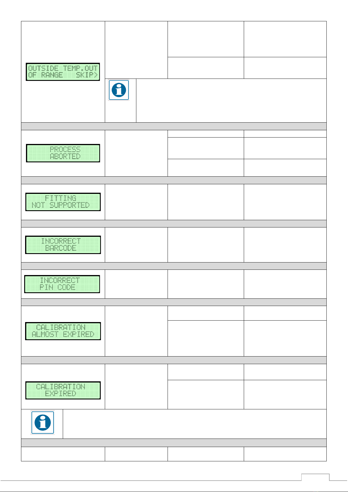
6. TROUBLESHOOTING
Message
Symptom
Possible cause
Solution
1. Device isn’t welding
1. Damaged fitting
1. Use new fitting
2. Damaged or mismatched
output adaptors
2. Check the condition of
adaptors, match the right
adaptors in relation to the
fitting output pin
3. Damaged cable
3. Deliver the device for service
1. Device isn’t welding
1. Too high/low temperature
of the transformer. Large
amount of welds performed
one after another without
breaks for cooling time
1. Leave the device in shaded
area until the temperature
returns to allowed level
2. Damaged temperature
sensor of the transformer
2. Deliver the device for service
INFORMATION
Fast mode is used always when machine is powered from the electrical grid.
Normal mode (if power source was correctly selected in settings menu) is
used only when power source was selected as power generator.
TRACEABILITY*
Device allows to record fitting and/or pipe information saved within the barcode. By
default this option is deactivated. Using buttons user can turn the traceability
on/off.
PIN CODE
Device can be locked with PIN code. If this function is activated, device will ask to enter
the pin code with each start.
INFORMATION
PIN code is located on the warranty card delivered together with the
device. PIN code is a factory set value and cannot be modified by the user.
Devices for some markets are delivered without the feature of PIN
protection.
FITTING TEST
In the device there is an option to turn on/turn off the fitting test, which is make before
the start of welding process (description page 23).
18
1. Too high/low outside
temperature. Allowed
temperature range 0-40°C
1. Make sure to level out the
outside temperature to
adequate by e.g. protecting the
device against direct sunlight,
welding in protective tent.
2. Damaged sensor of outside
temperature
2. Deliver the device for service
INFORMATION
There is an option to perform welding in emergency situations, even if the
temperature is outside allowed range. For that purpose choose SKIP option
by pressing the -> button. Weld performed in such conditions will be saved
in the memory with adequate error code.
1. Welding process got
aborted
1. Damaged fitting
1. Perform new weld
2. Output cable disconnected
from the fitting during
welding process
2. Perform new weld
3. Damaged output cable
3. Deliver the device for service
1. Device doesn’t allow
to start welding
process
1. Welding voltage or fitting
resistance are outside device
working range
1. Replace the fitting with the
one that is within the working
range of the welding unit or use
welding unit with higher
working parameters.
1. Device doesn’t start
welding process
1. Entered barcode is
incorrect
1. Enter the barcode again or
perform the welding process in
manual mode
1. Device doesn’t start
1. Entered PIN code is
incorrect
1. Correct PIN code can be
found on the warranty card
1. Calibration will soon
expire
1. Contact service department
to arrange calibration check
2. Invalid date and time
2. Check date and time settings
in device setting menu. If the
problem keeps occurring
deliver the device for service to
replace the internal battery.
1. Calibration got expired
1. Contact service department
to arrange calibration check
2. Invalid date and time
2. Check date and time settings
in device setting menu. If the
problem keeps occurring
deliver the device for service.
INFORMATION
Whenever the calibration expires, the device won’t stop working, and will return to normal work after
displaying message about expired calibration. Welds performed on welding unit without valid calibration
certificate are saved in the memory with adequate error code.
1. Device doesn’t start
1. Mains voltage is above
acceptable level of 265 V.
1. Check the mains parameters

Instrukcja
19
2. Power generator isn’t
working in stable manner
2. Send the power generator
for service
3. Damaged component
3. Deliver the device for service
1. Device doesn’t start
1. Mains voltage is below
acceptable level of 195 V.
1. Check the mains parameters
2. Power generator isn’t
working in stable manner
2. Send the power generator
for service
3. Damaged component
3. Deliver the device for service
1. Welding cannot be
carried
1. Welding current is outside
working range of the device
1. Short-circuit in welding
circuit
2. Use welding unit of higher
power or fitting with lower
power demand
3. Damaged welding unit –send
the device for service
1. Welding process got
aborted
1. Cables got disconnected
during welding process
1. Repeat the welding cycle
2. Damaged cable/s.
2. Deliver the device for service
1. Welding cannot be
carried
1. Supply current frequency
is outside allowed range
1. Check the mains/generator
2. Damaged welding unit
2. Deliver the device for service
7. MAINTENANCE
DANGER
Each maintenance work shall be performed while the power supply are disconnected from power outlet.
Use and maintenance
Device doesn’t require any special maintenance conditions, except for keeping it in general cleanness. Standard maintenance
works are limited to periodical cleaning of external surfaces of the device.
Electrical components
Pay special attention during storage, use and transport that the electrical components are not exposed to water (rain, drowning)
or moisture.
List of wear parts:
1. Electrical components: power supply cables, output cables;
2. Other: adaptors;
In case of failure turn off the device by pull the plug from power outlet. Such fact shall be immediately reported to the superior.
Warranty and post-warranty repairs are performed after delivering the device to the producer service department as stated in
warranty terms and conditions.
In accordance with requirements and provisions regarding welding devices, the welding unit is subjected to obligatory annual
inspection performed by the producer or other authorized entities. During the inspection a complete examination for correct
Table of contents
Popular Welding System manuals by other brands

Forney
Forney TIG quick start guide

ESAB
ESAB 350mpi instruction manual

Hobart Welding Products
Hobart Welding Products IronMan 275 owner's manual

WeldMate
WeldMate 60A Owner's Manual and Operating Instructions

Lincoln Electric
Lincoln Electric Linc Feed 24M Operator's manual

Hobart Welders
Hobart Welders H100L4-10 owner's manual

EWM
EWM T5.00-AC/DC Comfort 3.0 operating instructions

Lincoln Electric
Lincoln Electric LN-10 HEADS & CONTROLS IM587-B Operator's manual

Fire Power
Fire Power TIG 140 AC/DC operating manual

Fytech
Fytech FY-91G owner's manual

Sel
Sel genesis 200 ac-dc/tlh instruction manual

Lincoln Electric
Lincoln Electric PRO-CUT IM637-A Operator's manual


