Clever Acoustics ZM 102 User manual

1 1+2 2
2
3
456
7
8
100
19
ON
1 2 3
ZM 102
Audio Mixer
CHIME
LEVEL
OUTPUT
PTT 1 MIC/LINE 2 MIC/LINE 3 MIC/LINE 4 MIC/LINE 5 MIC/LINE 6 MIC/LINE 7 MIC/LINE 8 MIC/LINE 9 MIC/LINE 10 VOLUME POWER
ON
OFF
MASTER 1
MASTER 2
1 1+2 2
2
3
456
7
8
100
19
LEVEL
OUTPUT
SIG SIG SIG SIG SIG SIG SIG SIG SIG SIG
1 1+2 2
PRIORITY 2
PRIORITY 3
PRIORITY 4
2
3
456
7
8
100
19
LEVEL
OUTPUT
1 1+2 2
2
3
456
7
8
100
19
LEVEL
OUTPUT
1 1+2 2
2
3
456
7
8
100
19
LEVEL
OUTPUT
1 1+2 2
2
3
456
7
8
100
19
LEVEL
OUTPUT
1 1+2 2
2
3
456
7
8
100
19
LEVEL
OUTPUT
1 1+2 2
2
3
456
7
8
100
19
LEVEL
OUTPUT
1 1+2 2
2
3
456
7
8
100
19
LEVEL
OUTPUT
1 1+2 2
2
3
456
7
8
100
19
LEVEL
OUTPUT
1 1+2 2
2
3
456
7
8
100
19
LEVEL
OUTPUT 2
3
456
7
8
100
19
2
3
456
7
8
100
19
MODE
BASS
MIC
LINE
MODE
MIC
LINE
MODE
MIC
LINE
MODE
MIC
LINE
MODE
MIC
LINE
MODE
MIC
LINE
MODE
MIC
LINE
MODEMODE
MIC
LINE
MIC
LINE
– +
– +
– +
– +
BASS
MASTER 2
MASTER 1
TREBLE
TREBLE
+30-3-8-13
7
4
5
2
4
2
GND
PRIORITY
CHIME
LED PWR
MIC INPUT
1
3
5
6
7
1
3
6
REC
OUTPUTS
2 1 LINE 10 LINE 9 LINE 8 LINE 7
LEFT
RIGHT
12
3
12
3
12
3
12
3
12
3
12
3
12
3
12
3
12
3
MIC/LINE INPUTS
PTT 1
CHIME REMOTE
23456789
10 MIC/LINE INPUTS
POWER INPUT:
240V~50Hz
FUSE: T1A 250V
DC 24V 2A
POWER
CONSUMPTION
(max.): 13W
WARNING: TO REDUCE THE RISK OF FIRE OR ELECTRIC SHOCK.
DO NOT EXPOSE THIS EQUIPMENT TO RAIN OR MOISTURE
CAUTION
RISK OF ELECTRIC SHOCK
DO NOT OPEN. NO USER
SERVICABLE PARTS INSIDE
www.cleveracoustics.co.uk
ZM 102 Audio Mixer
User Manual
Order code: CRAM42
www.cleveracoustics.co.uk ZM 102 Audio Mixer User Manual
2
Safety advice
WARNING
FOR YOUR OWN SAFETY, PLEASE READ THIS USER MANUAL
CAREFULLY BEFORE YOUR INITIAL START-UP!
• Beforeyourinitialstart-up,pleasemakesurethatthereisnodamagecausedduringtransportation.
• Shouldtherebeanydamage,consultyourdealeranddonotusetheequipment.
• Tomaintaintheequipmentingoodworkingconditionandtoensuresafeoperation,itisnecessary
fortheusertofollowthesafetyinstructionsandwarningnoteswritteninthismanual.
• Pleasenotethatdamagescausedbyusermodicationstothisequipmentarenotsubjecttowarranty.
IMPORTANT:
The manufacturer will not accept liability for any resulting damages caused by the non-observance
of this manual or any unauthorised modication to the equipment.
OPERATING DETERMINATIONS
Ifthisequipmentisoperatedinanyotherway,thanthosedescribedinthismanual,theproductmaysufferdamageand
thewarrantybecomesvoid.Incorrectoperationmayleadtodangere.g:short-circuit,burnsandelectricshocksetc.
Donotendangeryourownsafetyandthesafetyofothers!
Incorrectinstallationorusecancauseseriousdamagetopeopleand/orproperty.
• Speaker&Ampliersystemscanproducehighsound
pressurelevels,pleaseoperateallcontrolswithcautionto
ensurepeoplearenotexposedtoexcessiveordangerous
soundpressurelevels.
• Neverletthepowercablecomeintocontactwithother
cables.Handlethepowercableandallmainsvoltage
connectionswithparticularcaution!
• Neverremovewarningorinformativelabelsfromtheunit.
• Donotopentheequipmentanddonotmodifytheunit.
• Donotswitchtheequipmentonandoffinshortintervals,
asthiswillreducethesystem’slife.
• Onlyusetheequipmentindoors.
• Donotexposetoammablesources,liquidsorgases.
• Alwaysdisconnectthepowerfromthemainswhen
equipmentisnotinuseorbeforecleaning!Onlyhandle
thepower-cablebytheplug.Neverpullouttheplugby
pullingthepower-cable.
• Makesurethattheavailablevoltage
is240V,50HzACor24VDC.
• Makesurethatthepowercableisnevercrimpedor
damaged.Checktheequipmentandthepowercable
periodically.
• Iftheequipmentisdroppedordamaged,disconnectthe
mainspowersupplyimmediatelyandhaveaqualied
engineerinspecttheequipmentbeforeoperatingagain.
• Iftheequipmenthasbeenexposedtodrastic
temperatureuctuation(e.g.aftertransportation),
donotconnectpowerorswitchitonimmediately.
Thearisingcondensationmightdamagetheequipment.
Leavetheequipmentswitchedoffuntilithasreached
roomtemperature.
• Ifyourproductfailstofunctioncorrectly,stopuse
immediately.Packtheunitsecurely(preferablyinthe
originalpackingmaterial),andreturnittoyourProlight
dealerforservice.
• Onlyusefusesofsametypeandrating.
• Repairs,servicingandpowerconnectionmustonlybe
carriedoutbyaqualiedtechnician.THISUNITCONTAINS
NOUSERSERVICEABLEPARTS.
• WARRANTY:Threeyearsfromdateofpurchase.
CAUTION!
KEEP THIS EQUIPMENT
AWAY FROM RAIN,
MOISTURE AND LIQUIDS
CAUTION!
TAKE CARE USING
THIS EQUIPMENT!
HIGH VOLTAGE-RISK
OF ELECTRIC SHOCK!!

www.cleveracoustics.co.uk ZM 102 Audio Mixer User Manual
3
Product overview & technical specications
Nineinputchannelsplusonededicated‘push-to-talk’microphoneinput,eachwithexibletwozonerouting
allowingtheinstallertocongurethesystemforpagingacrosslargerpremises.Adedicatedpagingmicrophone
offersremotechimeandpagingfunctions.
•Channel1isdedicatedtotheZM102microphone
andhaspriorityoverallinputs
•Channels2,3and4withVOXandpriority
selectoroverinputs5-10
•All10inputsfeaturemic,lineand300Hzhigh
passfilteringselector
•Inputs7-10featureXLRmicinputsand
stereophonoinputs
•TwobalancedXLRlineoutputs,oneperoutputzone
•Allinputsincludingchannels1-10,MICZM102,
chimecanberoutedtooutputzones1,2or1+2
•Built-intonepre-setchime,remotechime
triggerandlocaltriggeronfrontpanel
•Volumecontrolsareprovidedforthechime,
MIC1andinputchannels2-10
•Outputzones1and2featuresbassandtreble
tonecontrols
•Independentmasteroutputlevelcontrols
foroutputzones1and2
•LEDsignalindicatorsforinputs1-10
•PowerLED
•5segmentLEDoutputlevelmeters
•AC220V-240VorDC24Voperatingvoltage
•1U19”rackmountchassiswithbrushed
aluminiumfrontpanel
ZM 102 Audio Mixer
Specications ZM 102 Audio Mixer
Inputsensitivity/impedance MIC/LINE:
-5dBu(2.45mV)/5KohmsBAL
-10dBu(245mV)/5KohmsBAL
LINERCAIN:
-10dBu(245mV)/10KohmsUNBAL
Outputlevel/impedance MASTER1,2:
NOR+4dBu(21.23V)/200ohmsBAL
REC:
NOR0dBu(0.775mV)/10KohmsUNBAL
Frequencyresponse LessThan-0.5dB(20Hz~20KHz)
Signaltonoiseratio MIC:MORETHAN60dB
LINE:MORETHAN0.03%
Cross-talk MIC:MORETHAN60dB
LINE:MORETHAN75dB
Powerconsumption 13W
Powersupply 240VAC50Hzor24VDC
Fuse T1A250V
Dimensions 44x484x378mm
Weight 5.52kg
Ordercode CRAM42
1 1+2 2
2
3
456
7
8
100
19
ON
1 2 3
ZM 102
Audio Mixer
CHIME
LEVEL
OUTPUT
PTT 1 MIC/LINE 2 MIC/LINE 3 MIC/LINE 4 MIC/LINE 5 MIC/LINE 6 MIC/LINE 7 MIC/LINE 8 MIC/LINE 9 MIC/LINE 10 VOLUME POWER
ON
OFF
MASTER 1
MASTER 2
1 1+2 2
2
3
456
7
8
100
19
LEVEL
OUTPUT
SIG SIG SIG SIG SIG SIG SIG SIG SIG SIG
1 1+2 2
PRIORITY 2
PRIORITY 3
PRIORITY 4
2
3
456
7
8
100
19
LEVEL
OUTPUT
1 1+2 2
2
3
456
7
8
100
19
LEVEL
OUTPUT
1 1+2 2
2
3
456
7
8
100
19
LEVEL
OUTPUT
1 1+2 2
2
3
456
7
8
100
19
LEVEL
OUTPUT
1 1+2 2
2
3
456
7
8
100
19
LEVEL
OUTPUT
1 1+2 2
2
3
456
7
8
100
19
LEVEL
OUTPUT
1 1+2 2
2
3
456
7
8
100
19
LEVEL
OUTPUT
1 1+2 2
2
3
456
7
8
100
19
LEVEL
OUTPUT
1 1+2 2
2
3
456
7
8
100
19
LEVEL
OUTPUT 2
3
456
7
8
100
19
2
3
456
7
8
100
19
MODE
BASS
MIC
LINE
MODE
MIC
LINE
MODE
MIC
LINE
MODE
MIC
LINE
MODE
MIC
LINE
MODE
MIC
LINE
MODE
MIC
LINE
MODEMODE
MIC
LINE
MIC
LINE
– +
– +
– +
– +
BASS
MASTER 2
MASTER 1
TREBLE
+30-3-8-13
TREBLE
44mm
484mm
378mm
1 1+2 2
2
3
456
7
8
100
19
ON
1 2 3
ZM 102
Audio Mixer
CHIME
LEVEL
OUTPUT
PTT 1 MIC/LINE 2 MIC/LINE 3 MIC/LINE 4 MIC/LINE 5 MIC/LINE 6 MIC/LINE 7 MIC/LINE 8 MIC/LINE 9 MIC/LINE 10 VOLUME POWER
ON
OFF
MASTER 1
MASTER 2
1 1+2 2
2
3
456
7
8
100
19
LEVEL
OUTPUT
SIG SIG SIG SIG SIG SIG SIG SIG SIG SIG
1 1+2 2
PRIORITY 2
PRIORITY 3
PRIORITY 4
2
3
456
7
8
100
19
LEVEL
OUTPUT
1 1+2 2
2
3
456
7
8
100
19
LEVEL
OUTPUT
1 1+2 2
2
3
456
7
8
100
19
LEVEL
OUTPUT
1 1+2 2
2
3
456
7
8
100
19
LEVEL
OUTPUT
1 1+2 2
2
3
456
7
8
100
19
LEVEL
OUTPUT
1 1+2 2
2
3
456
7
8
100
19
LEVEL
OUTPUT
1 1+2 2
2
3
456
7
8
100
19
LEVEL
OUTPUT
1 1+2 2
2
3
456
7
8
100
19
LEVEL
OUTPUT
1 1+2 2
2
3
456
7
8
100
19
LEVEL
OUTPUT 2
3
456
7
8
100
19
2
3
456
7
8
100
19
MODE
BASS
MIC
LINE
MODE
MIC
LINE
MODE
MIC
LINE
MODE
MIC
LINE
MODE
MIC
LINE
MODE
MIC
LINE
MODE
MIC
LINE
MODEMODE
MIC
LINE
MIC
LINE
– +
– +
– +
– +
BASS
MASTER 2
MASTER 1
TREBLE
TREBLE
+30-3-8-13
7
4
5
2
4
2
GND
PRIORITY
CHIME
LED PWR
MIC INPUT
1
3
5
6
7
1
3
6
REC
OUTPUTS
2 1 LINE 10 LINE 9 LINE 8 LINE 7
LEFT
RIGHT
12
3
12
3
12
3
12
3
12
3
12
3
12
3
12
3
12
3
MIC/LINE INPUTS
PTT 1
CHIME REMOTE
23456789
10 MIC/LINE INPUTS
POWER INPUT:
240V~50Hz
FUSE: T1A 250V
DC 24V 2A
POWER
CONSUMPTION
(max.): 13W
WARNING: TO REDUCE THE RISK OF FIRE OR ELECTRIC SHOCK.
DO NOT EXPOSE THIS EQUIPMENT TO RAIN OR MOISTURE
CAUTION
RISK OF ELECTRIC SHOCK
DO NOT OPEN. NO USER
SERVICABLE PARTS INSIDE
www.cleveracoustics.co.uk

www.cleveracoustics.co.uk ZM 102 Audio Mixer User Manual
4
1 1+2 2
2
3
456
7
8
100
19
ON
1 2 3
ZM 102
Audio Mixer
CHIME
LEVEL
OUTPUT
PTT 1 MIC/LINE 2 MIC/LINE 3 MIC/LINE 4 MIC/LINE 5 MIC/LINE 6 MIC/LINE 7 MIC/LINE 8 MIC/LINE 9 MIC/LINE 10 VOLUME POWER
ON
OFF
MASTER 1
MASTER 2
1 1+2 2
2
3
456
7
8
100
19
LEVEL
OUTPUT
SIG SIG SIG SIG SIG SIG SIG SIG SIG SIG
1 1+2 2
PRIORITY 2
PRIORITY 3
PRIORITY 4
2
3
456
7
8
100
19
LEVEL
OUTPUT
1 1+2 2
2
3
456
7
8
100
19
LEVEL
OUTPUT
1 1+2 2
2
3
456
7
8
100
19
LEVEL
OUTPUT
1 1+2 2
2
3
456
7
8
100
19
LEVEL
OUTPUT
1 1+2 2
2
3
456
7
8
100
19
LEVEL
OUTPUT
1 1+2 2
2
3
456
7
8
100
19
LEVEL
OUTPUT
1 1+2 2
2
3
456
7
8
100
19
LEVEL
OUTPUT
1 1+2 2
2
3
456
7
8
100
19
LEVEL
OUTPUT
1 1+2 2
2
3
456
7
8
100
19
LEVEL
OUTPUT 2
3
456
7
8
100
19
2
3
456
7
8
100
19
MODE
BASS
MIC
LINE
MODE
MIC
LINE
MODE
MIC
LINE
MODE
MIC
LINE
MODE
MIC
LINE
MODE
MIC
LINE
MODE
MIC
LINE
MODEMODE
MIC
LINE
MIC
LINE
– +
– +
– +
– +
BASS
MASTER 2
MASTER 1
TREBLE
TREBLE
+30-3-8-13
7
4
5
2
4
2
GND
PRIORITY
CHIME
LED PWR
MIC INPUT
1
3
5
6
7
1
3
6
REC
OUTPUTS
2 1 LINE 10 LINE 9 LINE 8 LINE 7
LEFT
RIGHT
12
3
12
3
12
3
12
3
12
3
12
3
12
3
12
3
12
3
MIC/LINE INPUTS
PTT 1
CHIME REMOTE
23456789
10 MIC/LINE INPUTS
POWER INPUT:
240V~50Hz
FUSE: T1A 250V
DC 24V 2A
POWER
CONSUMPTION
(max.): 13W
WARNING: TO REDUCE THE RISK OF FIRE OR ELECTRIC SHOCK.
DO NOT EXPOSE THIS EQUIPMENT TO RAIN OR MOISTURE
CAUTION
RISK OF ELECTRIC SHOCK
DO NOT OPEN. NO USER
SERVICABLE PARTS INSIDE
www.cleveracoustics.co.uk
Panel & connection identication
16-ACMainsPowerInput
17-DCPowerInput
18-BalanceMainOutputs
19-Record/LineOutputs
20-LineInputs7-10
21-MIC/LineInputs7-10
22-MIC/LineInputs2-6
23-PagingMicrophoneInput
24-ChimeInterface
01-ChimeVolumeControl
02-ChimeActivation
03-PagingMicrophoneVolumeControl
04-MIC/LineVolumeControl
05-ModeSwitch
06-OutputLevelIndicator
07-MasterZone1LF/HFControls
08-MasterZoneOutput
VolumeControls
09-PowerIndicatorLED
10-ChimeOutputSelect
11-SignalIndicatorLED
12-OutputZoneRoutingSelection
13-PrioritySelection
14-MasterZone2LF/HFControls
15-PowerSwitch
16 17 242318 20 21 2219
Front Panel Layout:
Rear Panel Layout:
1 1+2 2
2
3
456
7
8
100
19
ON
1 2 3
ZM 102
Audio Mixer
CHIME
LEVEL
OUTPUT
PTT 1 MIC/LINE 2 MIC/LINE 3 MIC/LINE 4 MIC/LINE 5 MIC/LINE 6 MIC/LINE 7 MIC/LINE 8 MIC/LINE 9 MIC/LINE 10 VOLUME POWER
ON
OFF
MASTER 1
MASTER 2
1 1+2 2
2
3
456
7
8
100
19
LEVEL
OUTPUT
SIG SIG SIG SIG SIG SIG SIG SIG SIG SIG
1 1+2 2
PRIORITY 2
PRIORITY 3
PRIORITY 4
2
3
456
7
8
100
19
LEVEL
OUTPUT
1 1+2 2
2
3
456
7
8
100
19
LEVEL
OUTPUT
1 1+2 2
2
3
456
7
8
100
19
LEVEL
OUTPUT
1 1+2 2
2
3
456
7
8
100
19
LEVEL
OUTPUT
1 1+2 2
2
3
456
7
8
100
19
LEVEL
OUTPUT
1 1+2 2
2
3
456
7
8
100
19
LEVEL
OUTPUT
1 1+2 2
2
3
456
7
8
100
19
LEVEL
OUTPUT
1 1+2 2
2
3
456
7
8
100
19
LEVEL
OUTPUT
1 1+2 2
2
3
456
7
8
100
19
LEVEL
OUTPUT 2
3
456
7
8
100
19
2
3
456
7
8
100
19
MODE
BASS
MIC
LINE
MODE
MIC
LINE
MODE
MIC
LINE
MODE
MIC
LINE
MODE
MIC
LINE
MODE
MIC
LINE
MODE
MIC
LINE
MODEMODE
MIC
LINE
MIC
LINE
– +
– +
– +
– +
BASS
MASTER 2
MASTER 1
TREBLE
TREBLE
+30-3-8-13
7
4
5
2
4
2
GND
PRIORITY
CHIME
LED PWR
MIC INPUT
1
3
5
6
7
1
3
6
REC
OUTPUTS
2 1 LINE 10 LINE 9 LINE 8 LINE 7
LEFT
RIGHT
12
3
12
3
12
3
12
3
12
3
12
3
12
3
12
3
12
3
MIC/LINE INPUTS
PTT 1
CHIME REMOTE
23456789
10 MIC/LINE INPUTS
POWER INPUT:
240V~50Hz
FUSE: T1A 250V
DC 24V 2A
POWER
CONSUMPTION
(max.): 13W
WARNING: TO REDUCE THE RISK OF FIRE OR ELECTRIC SHOCK.
DO NOT EXPOSE THIS EQUIPMENT TO RAIN OR MOISTURE
CAUTION
RISK OF ELECTRIC SHOCK
DO NOT OPEN. NO USER
SERVICABLE PARTS INSIDE
www.cleveracoustics.co.uk
12 3 4 5 6 7 8 9
1110 12 13 14 15

www.cleveracoustics.co.uk ZM 102 Audio Mixer User Manual
5
Layout identication:
1. Chime Volume Control
Thechimeoutputvolumeisadjustable.Turnthelevelcontrolanticlockwisetothelowestsetting,
orturnclockwisetoadjusttothehighestsetting.
2. Chime Activation
PresstoactivatetheChimefunction.Thechimefunctionhaspriorityoverallchannels,
mutingthechannels5-10whenthechimeisactivated.
3. Paging Microphone Volume Control
Thepagingmicrophonevolumeisadjustable.Turnthelevelcontrolanticlockwisetothelowestsetting,
orturnclockwisetoadjusttothehighestsetting.Whenthepagingmicrophoneisactivated,themixer
willmustchannels5-10.
4. MIC/Line Volume Control
EachoftheMIC/Linevolumesareadjustable.Turnthelevelcontrolanticlockwisetothelowestsetting,
orturnclockwisetoadjusttothehighestsetting.
5. Mode Switch
ThemodeswitchallowstheinstallertochoosefromeitherMICorLinelevelsignalinputs.
MIC:Microphonelevelinputwith300Hzhighpasslter.ActivatetheMICtoreducestage
rumbleortoimprovetheintelligibilitywhenusingtraditional100Vhornspeakers.
MIC:Fullrangemicrophonelevelinput.
LINE:FullrangelinelevelinputforusewithaudiosourcessuchasCDplayers&radiotuners.
6. Output Level Indicator
Theoutputlevelindicator(VUmeter)hasthreegreenLEDs,oneamberLEDandoneredLED.During
normaloperation,theoutputmetershouldshowonlygreenLEDs.Astheoutputreachesmaximum,the
amberLEDwillilluminatefollowedbytheredLEDtoindicate+3dBoversignal.
7. Master Zone 1 LF/HF Controls
Duringinitialsetupthehighfrequencyandlowfrequencytoneadjustmentsshouldbesettothezero
point(3O'clockposition).Turnthelevelcontrolanticlockwisetoreducethehigh/lowfrequencytones,
orturnclockwisetoadjusttheincreasethehigh/lowfrequencytones.Adjustmentsshouldbemade
graduallytoavoidanysuddenchangestotheaudiooutput.
8. Master Zone Output Volume Controls
Themonitoroutputvolumeisadjustable.Turnthelevelcontrolanticlockwisetothelowestsetting,
orturnclockwisetoadjusttothehighestsetting.Thisisusedtocontrolthevolumeforthe1W8ohm
loudspeakeroutputontherearpanelofthezonemixer.
Operating instructions

www.cleveracoustics.co.uk ZM 102 Audio Mixer User Manual
6
Operating instructions
9. Power Indicator LED
ThePowerLEDwillilluminatetoindicatethezonemixerispoweredon.IfthepowerLEDis
notilluminated,checkrstthepositionoftheon/offswitchandthencheckthemainssupply
(includingfuse).
10. Chime Output Select
Thechimefunctionmayberoutedtooutputzone1,outputzone2orboth.Usetheslideswitch
toselectasrequired.
11. Signal Indicator LED
EachoftheinputchannelsfeaturesanLEDtogiveavisualindicationifaninputsignalpresent
ontherelevantchannel.
12. Output Zone Routing Selection
Theoutputofeachindividualinputchannelmayroutedtooutputzone1,outputzone2orboth.
Usetheslideswitchtoselectasrequired.
13. Priority Selection
TheusermayselectfromeitherMIC/LINE2,MIC/LINE3orMIC/LINE4tobehighestpriority.Usinga
smallscrewdriver,carefullyremovethesmallprotectioncovertotherightofMIC/LINE2inorderto
revealthethreewaydipswitch.ToswitchpriorityONforagivenchannel,movethedipswitchtothe
ONposition.Note:Onlyonechannelshouldbeselectedatanyonetime.
14. Master Zone 2 LF/HF Controls
Duringinitialsetupthehighfrequencyandlowfrequencytoneadjustmentsshouldbesettothezero
point(3O'clockposition).Turnthelevelcontrolanticlockwisetoreducethehigh/lowfrequencytones,
orturnclockwisetoadjusttheincreasethehigh/lowfrequencytones.Adjustmentsshouldbemade
graduallytoavoidanysuddenchangestotheaudiooutput.
15. Power Switch
On/Offcontrolforthezoneamplier.
16. AC Mains Power Input
240V~50HzACmainsvoltageinput.ThisproductfallsunderCLASS1andmusthaveaprotective
earthconnectionatalltimes.
17. DC Power Input
Forconnectiontobatterybackuppowersources,orforoperationfromleisuretypebatteries.TheZM
102mixermaybeusedfrom24VDCpowersources.Careshouldbetakentoensureaninlinefuseis
ttedtothe+vesupplyandthepowerisconnectedwithobservingthepolarity.
18. Balance Main Outputs
Balanced,+4dBumonooutputsforeachofthetwooutputzones.Eachzoneoutputfeatures
amaleXLRconnector.

www.cleveracoustics.co.uk ZM 102 Audio Mixer User Manual
7
Operating instructions
19. Record / Line Outputs
Unbalanced,0dBumonooutputsforeachofthetwooutputzones.Eachzoneoutputfeaturesafemale
phono(RCA)connector.Theoutputvolumefortherecordoutputsisxedandisnotalteredbythe
mastervolumecontrolforthezoneoutputs.Thewhitephonosocketoutputszone2,whilethered
phonosocketoutputszone1.
20. Line Inputs 7-10
Unbalanced,-10dBV(245mV)lineinputsforchannels7-10suitableforusewithaudiosourcessuchas
CDplayersorFMTuners.Eachstereoinputfeaturesapairoffemalephono(RCA)connectors,summed
tomonointernally.SelectionoftheLineinputmustbemadeviathefrontpanelMODEselector
switches.
21. MIC/Line Inputs 7-10
MIC/Lineinputs7-10allfeaturebalanced,monoaudioinputs,switchableMIC,MICwithLowCutor
LINE.WhenusedineitherMICorMICwithLowCutmode,themixerwillprovide48Vphantompower.
Toreducestagerumble,themixerfeaturesMICwithLowCutmodewherea300Hzhighpassltermay
beenabletohelpreducebackgroundnoiseandincreaseintelligibility.
ForLINEinput,themixerfeaturesapairofstereophonosockets(summedtomonointernally)foreach
oftheinputchannels.TousetheLINEinput,usetheselectorswitchonthefrontpanelofthemixer.
22. MIC/Line Inputs 2-6
MIC/Lineinputs7-10allfeaturebalanced,monoaudioinputs,switchableMIC,MICwithLowCutor
LINE.WhenusedineitherMICorMICwithLowCutmode,themixerwillprovide48Vphantompower,
selectionismadeviatheswitchonthefrontpanel.Toreducestagerumble,themixerfeaturesMIC
withLowCutmodewherea300Hzhighpassltermaybeenabletohelpreducebackgroundnoiseand
increaseintelligibility.TousetheLINEinput,usetheselectorswitchonthefrontpanelofthemixer.
23. Paging Microphone Input
DedicatedinputforthePMZM102Pagingmicrophone.
Pin1=Microphone+ve(hot)
Pin2=MicrophoneGround
Pin3=Microphone–ve(cold)
Pin4=FunctionGround
Pin5=PriorityActivate(shorttoFunctionGround)
Pin6=ChimeActivate(shorttoFunctionGround)
Pin7=LEDPower(24VDC)
24. Chime Interface
Toactivatethechimefunction,aconnectionshouldbemadebetweenthetwoterminalsbythewayof
acontactclosurerelay.Thevolumeforthechimemaybeadjustedonthefrontpaneloftheunit.

www.cleveracoustics.co.uk ZM 102 Audio Mixer User Manual
8
Operating instructions
Power On/Off Procedure
Priortomakinganyconnectiontothemainspoweroraudioinputs/outputs,turnalllevelcontrols
counterclockwisetothe“min”positionandalltone(equaliser)controlstothemid(zero)point.
Switchonthezonemixerandanyaudiosources(MP3players,CDplayers,Microphonesetc)before
poweringthesystemsamplierON.Thelastproducttobeswitchedonshouldbethepower/slave
amplierstopreventanyunwantednoiseorpotentialdamagetospeakersorampliers.Ifyouwish
topoweroffthesystem,turntheamplier’smastervolumecontrolcounterclockwisetothe“min”
positionbeforeswitchingtheamplierOFFbeforeanyaudiosourcesareswitchedoff.Byfollowingthis
procedureitwillpreventacousticshockstothespeakersorpotentialdamagetosystemcomponents.
Afterconnectingallaudiosourcesandpoweringonthesystem,adjustthelevelofeachaudioinput,
selectthezoneroutinginordertoachievethedesired“mix”foreachzone.Careshouldbetaken
towhenadjustingmicrophoneinputvolumesandthemastervolume,adjustbothoftheseinsmall
increment’stoavoidfeedback(howlaround).Thegoalistoachieveaclearbalancebetweenmusic
andvoiceensuringannouncementscanbeclearlyheard.
www.cleveracoustics.co.uk ZM 102 Audio Mixer User Manual
9
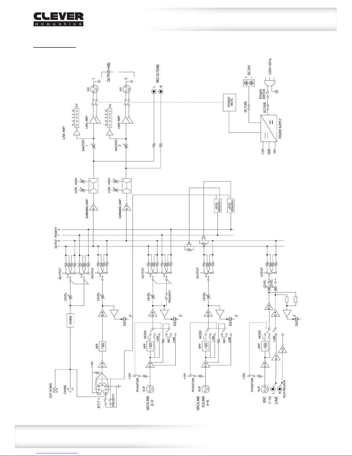
Block Diagrams
Block Diagram:

www.cleveracoustics.co.uk ZM 102 Audio Mixer User Manual
10
Typical panel connections
Typical Panel Connections:

www.cleveracoustics.co.uk ZM 102 Audio Mixer User Manual
11
WEEE notice
Correct Disposal of this Product
(Waste Electrical & Electronic Equipment)
(Applicable in the European Union and other European countries
with separate collection systems)
Thismarkingshownontheproductoritsliterature,indicatesthatitshouldnotbedisposed
withotherhouseholdwastesattheendofitsworkinglife.Topreventpossibleharmtothe
environmentorhumanhealthfromuncontrolledwastedisposal,pleaseseparatethisfromother
typesofwastesandrecycleitresponsiblytopromotethesustainablereuseofmaterialresources.
Householdusersshouldcontacteithertheretailerwheretheypurchasedthisproduct,ortheir
localgovernmentofce,fordetailsofwhereandhowtheycantakethisitemforenvironmentally
saferecycling.
Businessusersshouldcontacttheirsupplierandcheckthetermsandconditionsofthe
purchasecontract.Thisproductshouldnotbemixedwithothercommercialwastesfordisposal.

www.cleveracoustics.co.uk ZM 102 Audio Mixer User Manual
12
Table of contents
Other Clever Acoustics Music Mixer manuals


