3 / 45
Table of contents
1.
Warranty........................................................................................................................................... 7
2.
Safety instructions............................................................................................................................ 7
2.1.
FOR SAFE AND EFFICIENT OPERATION............................................................................ 7
2.2.
Important mains plug wiring instructions ................................................................................. 8
3.
Introduction....................................................................................................................................... 9
3.1.
Foreword.................................................................................................................................. 9
4.
View of the mixing console............................................................................................................... 9
4.1.
Front view................................................................................................................................ 9
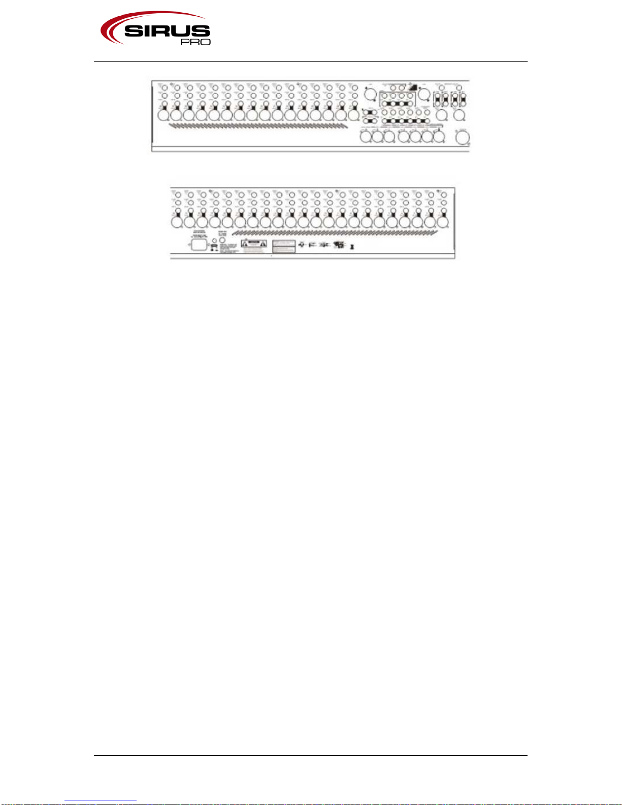
4.2.
Back view................................................................................................................................. 9
5.
Introduction to the mixing console.................................................................................................. 10
6.
Installing the console......................................................................................................................11
6.1.
Grounding.............................................................................................................................. 11
6.2.
Switching the console on or off.............................................................................................. 12
7.
Audio connections.......................................................................................................................... 12
7.1.
General overview................................................................................................................... 12
7.2.
Required connection cables.................................................................................................. 14
7.3.
Dealing with ground loops, buzz and interference ................................................................14
7.4.
Balanced connections ........................................................................................................... 15
8.
Connections at the mixing console ................................................................................................ 15
8.1.
MONO CHANNEL MIC/LINE IN............................................................................................ 15
8.2.
STEREO CHANNEL MIC IN/OUT; LINE IN.......................................................................... 15
8.2.1.
STEREO CHANNEL MIC IN ......................................................................................... 15
8.2.2.
STEREO CHANNEL MIC OUT ..................................................................................... 15
8.2.3.
STEREO CHANNEL LINE IN........................................................................................ 16
8.3.
INSERT.................................................................................................................................. 16
8.4.
DIRECT OUTPUT ................................................................................................................. 16
8.5.
LAMP..................................................................................................................................... 16
8.6.
GROUP; L; R; M OUT ...........................................................................................................16
8.7.
AUX OUT 1-6......................................................................................................................... 17
8.8.
MATRIX OUT 1-4 .................................................................................................................. 17
8.9.
MATRIX EXT IN 1-4 .............................................................................................................. 17
8.10.
2-TRACK IN and OUT........................................................................................................... 18
8.11.
MONITOR OUT..................................................................................................................... 18
9.
Input channel.................................................................................................................................. 19
9.1.
Mono...................................................................................................................................... 19
9.1.1.
+48V .............................................................................................................................. 19
9.1.2.
Polarity........................................................................................................................... 19