CLF Lighting EF SMOKE 3100 User manual

manual
V1.0 APRIL 2018WWW.CLF-LIGHTING.COM
ef smoke 3100

WWW.CLF-LIGHTING.COM
2
Machine overview 3
Safety instruction 4
AC power 6
Data link 6
Physical installation 7
Operating instructions 7
Menu navigation 8
DMX channels 9
Maintenance 10
Specications 11
table of CONTENTS
WWW.CLF-LIGHTING.COM
3
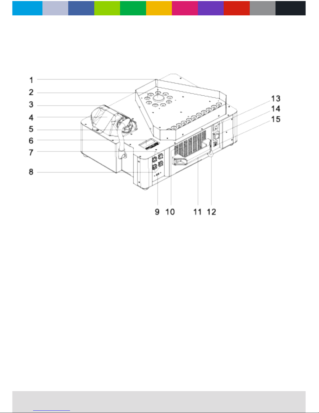
machine overview
1. Nozzle
2. LED
3. 2,5L tank
4. Tank xing plate
5. Fluid tube
6. LCD display
7. 3-pin DMX socket
8. 5-pin DMX socket
9. USB
10. Ventilation
11. Handle
12. Safety point
13. Power switch
14. PoweCON
15. Overload protection

WWW.CLF-LIGHTING.COM
4
Safety Instruction
The following symbols are used to identify important safety information on the product and in this manual:
WARNING!
Read the safety precautions in this section before
installing, powering, operating or servicing this
product
DANGER!
Safety hazard.
Risk of severe
injury or death.
DANGER!
Hazardous
voltage. Risk of
lethal or severe
electric shock.
WARNING!
Fire hazard.
WARNING!
LED light
emission. Risk of
eye injury.
WARNING!
Burn hazard. Hot
surface. Do not
touch.
WARNING!
Wear protective
eyewear.
WARNING!
Referto user
manual.
Using for the rst time
This product is for professional use only. It is not for household use.
This product presents risks of severe injury or death due to re and burn hazards, electric shock and falls.
Read this manual before installing, powering or servicing the xture, follow the safety precautions listed below
and observe all warnings in this manual and printed on the xture. If you have questions about how to operate the
xture safely, please contact your supplier.
PROTECTION FROM ELECTRIC SHOCK
• Disconnect the machine from AC power before removing or installing any cover or part and when not in use
• Always ground (earth) the xture electrically.
• Use only a source of AC power that complies with local building and electrical codes and has both overload
and ground-fault (earth-fault) protection.
• Before using the machine check that all power distribution equipment and cables are in perfect condition
and rated for the current requirements of all connected devices.
• Power input and throughput cables must be rated 20 A minimum, have three conductors 1.5 mm² (16 AWG)
minimum conductor size and an outer cable diameter of 5 - 15 mm . Cables must be hard usage type (SJT
or equivalent) and heat-resistant to 90° C minimum.
• Use only PowerCON® cable connectors to connect to power input sockets. Use only PowerCON® cable
connectors to connect to power through put sockets.
• Isolate the machine from power immediately if the power plug or any seal, cover, cable, or other component
is damaged, defective, deformed, wet or showing signs of overheating. Do not reapply power until repairs
have been completed.
Do not expose the xture to rain or moisture
CLF EF Smoke 3100 has an IP20 rating, indoor use only.

WWW.CLF-LIGHTING.COM
5
Safety Instruction
PROTECTION FROM BURNS AND FIRE
• Do not operate the machine if the ambient temperature (Ta) exceeds 45°C.
• The exterior of the machine becomes hot during use. Avoid contact by persons and materials. Allow the
machine to cool for at least 10 minutes before handling.
• Keep all combustible materials (e.g. fabric, wood, paper) at least 100 mm away from the nozzle
• Keep ammable materials well away from the machine
• Ensure that there is free and unobstructed airow around the machine
• Do not place objects within 200 mm of the machine
• Do not attempt to bypass thermostatic switches or fuses.
• If you relay power from one machine to another using power throughput sockets, do not connect more than
1 machines in total to each other in an interconnected chain.
• Connect only other machines to xture power throughput sockets. Do not connect any other type of device
to these sockets.
• Do not connect any other type of device to these sockets.
• Do not stick lters, masks or other materials onto any optical component.
• Do not modify the machine in any way not described in this manual
• Do not connect machine to a dimmer
PROTECTION FROM INJURY
• Ensure that persons are not looking at the LEDs from within 3 meters when the product lights up suddenly.
This can happen when power is applied, when the product receives a DMX signal, or when SERVICE menu
items are selected.
• Fasten the xture securely to a xed surface or structure when in use. The xture is not portable when
installed.
• Ensure that any supporting structure and/or hardware used can hold at least 10 times the weight of all the
devices they support.
• Allow enough clearance around the head to ensure that it cannot collide with an object or another xture
when it moves.
• Check that all external covers and rigging hardware are securely fastened.
• Block access below the work area and work from a stable platform whenever installing, servicing or moving
the machine
• Do not operate the machine with missing or damaged covers, shields or any optical component.
WWW.CLF-LIGHTING.COM
6
ac power
power voltage
Check that the voltage range specied on the machine serial number label matches the local AC mains
power voltage before applying power to the xture. The machine accepts AC mains power at 100-240 V
nominal, 50/60 Hz. Do not apply AC mains power to the machine at any other voltage than specied.
power cables
Power input and throughput cables must be rated 20 A minimum, have three conductors 1.5 mm² (16 AWG)
minimum conductor size and an outer cable diameter of 5 - 15 mm. Cables must be hard usage type (SJT or
equivalent) and heat- resistant to 90°C minimum. In the EU the cable must be HAR approved or equivalent.
If you install a power plug on the power cable, install a grounding-type (earthed) plug that is rated 20 A mini-
mum. Follow the plug manufacturer’s instructions. Table 1 shows standard wire color-coding schemes and some
possible pin identication schemes; if pins are not clearly identied, or if you have any doubts
Wire color (EU models) Wire color (US models) Conductor Symbol Screw (US)
Brown Black Live LYellow or Brass
Blue White Neutral N Silver
Yellow / green Green Ground (earth) Green
Table 1: Wire color-coding and power connections
or
data link
A DMX 512 data link is required in order to control a machine via DMX. The machine has 3 & 5-pin XLR connectors for DMX data
input and output. The pin-out on all connectors is pin 1 = shield, pin 2 = cold (-), and pin 3 = hot (+) Pins 4 and 5 in the 5-pin XLR
connectors are not used.
tips for reliable data transmission
To connect the machine to data:
1. Connect the DMX data output from the controller to the closest machines male 3 & 5-pin XLR DMX input connector.
2. Connect the DMX output of the machine closest to the controller to the DMX input of the next machine and continue
connecting machines output to input.
WWW.CLF-LIGHTING.COM
7
physical installation
Warning! The machine must be either fastened to a at surface such as a stage or wall, or clamped to a truss or
similar structure in any orientation using a rigging clamp.
Warning! At all times machine can cause injury or damage it if falls, attach an approved safety cable to one of the
safety cable attachment points on the base (see “machine overview” on page 4).
Check that all surfaces more far aways then a minimum of 200 mm. from the machine, that combustible materials
(wood, fabric, paper, etc.) are minimum 100 mm. from the nozzle, that there is free airow around the machine
and that there are no ammable materials nearby.
Fastening the machine to a at surface
The machine can be fastened to a xed at surface that is oriented at any angle. Check that the surface
can support at least 10 times the weight of all machines and equipment to be installed on it.
Warning! The supporting surface must be at otherwise the air vents in the base may be blocked, which will cause
overheating. Fasten the machine securely. Do not place it on a surface or leave it where it can be moved or can fall
over. Attach a securely anchored safety cable to the safety cable attachment point (see “machine overview” on page.
If the machine is installed in any location where it may fall and cause injury or damage if the primary attachment
fails:
1. Block access under the work area. Working from a stable platform.
2. Secure the machine with a secondary attachment such as an approved safety cable that is rated for the
weight of the machine using one of the attachment points at the edges of the base (see “machine overview”
on page 4). Do not use any other part of the machine as a safety cable attachment point.
operating instructions
1. After checking that all the parts are intact and complete, position the machine on a at surface.
2. Only use designated CLF Lighting smoke liquid. Machine can be harmed when using other uids and warranty is expired.
3. Connecting the power cord. Before power on, make sure it is connected with the rated voltage.
4. Turn on the machine, it will immediately start heating up, the digital display will show “WARMING UP”.
Menu instruction
1. MENU button: When it shows “HEAT”, press “menu” button to enter the page “ADDR”
2. UP button: Increase the relevant value of each page
3. DOWN button: Decrease the relevant value of each pag
4. ENTER button: Enter or exit each page
Wireless Controll
When the unit is powered on, and the wireless status is ON, the LCD display will show “wireless setup”. In such case, user can register
the wireless remote by pressing any button for 1s on the remote. If the LCD display ickers twice, then it is matched with the unit suc-
cessfully. One unit can match with 5 remotes at most. If user register the sixth one, then the memory for the rst ve remotes will be
erased. Press ON button to run the unit or OFF button to stop it. When the machine is under wireless remote control, the haze output
is the one set by VOLUME OUT. For example, if the VOLUME OUT is 1%, then it will be 1% when controlled by wireless remote.
Press button A to run, release it to stop. The operation of B,C,D is same as button A.
Note:
1. When matching the wireless remote, please make sure the LCD display icker twice. Then release the A button to match the
wireless remote, Otherwise, it might fail.
2. If the wireless remote setup is OFF(i.e. LCD displays “Wireless Set OFF”), when the machine is powered on again, the LCD
display will not show “wireless setup”.
3. Wireless remote control will void if the unit is connected to DMX.

WWW.CLF-LIGHTING.COM
8
menu navigation
MENU: Scroll through setting menu;
UP: Increase, multiplex “TIMER” button;
DOWN: Decrease, multiplex “VOLUME” button;
ENTER: In/Out, multiplex “stop” button;
Press “ MENU ” button to switch dierent pages, 10 pages in total:
1. Ready To Fog: The machine is ready to work
2. Interval Set: To set the interval of timer mode , adjustable from 1~200s
3. Duration Set: To set the duration of timer mode , adjustable from 1~200s
4. Channel A from 0-10 Set the color when triggered by wireless remote controller button A
5. Channel B from 0-10 Set the color when triggered by wireless remote controller button B
6. Channel C from 0-10 Set the color when triggered by wireless remote controller button C
7. Channel D from 0-10 Set the color when triggered by wireless remote controller button D
8. DMX512 Address: The DMX address can be set up from 1 to 512
9. Wireless Set: To turn on/o the wireless function
10. Language: Select the language saved by “Enter”
When the machine is not working, press “Stop” to Exit. When the machine is working, press “Stop” to stop machine working and
go back to home page. Press UP or DOWN to change the value in each setting page. At home page, press TIMER button to
activate timer mode, LCD displays as below:
• Interval 10s: Interval countdown
• Duration 10s: Duration countdown
The two pages will display circularly when each countdown nish, “Interval” and “Duration” time could be set in page 2 and 3. At
home page, press VOLUME button to activate volume mode, the machine starts to fog
At Channel A page, press ENTER button to LED color setting page. Press UP and DOWN to choose color. Press ENTER to save
and exit the setting. There are total 11 LED color modes, which are “OFF”, “Co1-Co9” (9 colors) and “random color changing
(rand)” mode. The color setting of Channel A wil be eected when press button A of the wireless controller.
1. When set to OFF, the LED would not light up.
2. 9 colors are as following:
• Co 1: Red • Co 6: Orange
• Co 2: Green • Co 7: Yellow
• Co 3: Blue • Co 8: Sky blue
• Co 4: Pink • Co 9: White
• Co 5: Purple
After setting the color, the corresponding color will light up when output controlled by wireless remoter. When Random mode, the
LED will change color randomly, the interval is 1s.
Note: When connected to DMX controller, the color setting from this page will be invalid, the LED color would be controlled by
DMX controller
Wireless remote control button 1-4 trigger the options set in the color program CH-1-CH-4,
respectively. DMX When connected DMX controller, the LCD shows DMX address setting page only, to easily set DMX address.

WWW.CLF-LIGHTING.COM
9
uid
dmx channels
Channel Function Value Percentage Remark
CH 1 FOG output 010 - 255 0 - 100% 000 - 009 = OFF
CH 2 Inner LED red output 010 - 255 0 - 100% 000 - 009 = OFF
CH 3 Inner LED green output 010 - 255 0 - 100% 000 - 009 = OFF
CH 4 Inner LED green output 010 - 255 0 - 100% 000 - 009 = OFF
CH 5 Outer LED red output 010 - 255 0 - 100% 000 - 009 = OFF
CH 6 Outer LED green output 010 - 255 0 - 100% 000 - 009 = OFF
CH 7 Outer LED blue output 010 - 255 0 - 100% 000 - 009 = OFF
CH 8 Color Macro 010 - 255 0 - 100% 000 - 009 = OFF
CH 9 Color Macro speed 010 - 255 0 - 100% 000 - 009 = OFF
CH 10 LED strobe 010 - 255 0 - 100% 000 - 009 = OFF
CH 11 LED dimmer 010 - 255 0 - 100% 000 - 009 = OFF
This machine use electronic program to detect whether there is uid inside tube or not, hence to protect the pump from being damaged
when there is no uid.
1. How to activate “low-uid protection”. When the and activate it, so when the internal inspection module check out there is no oil
inside the tube but the machine is still working, then the machine will get into oil free protection 20s later by shutting the pump o.
The digital display will keep ashing.
2. How to release “low-uid protection”. When the machine is under the protection of low uid, after relling the uid, there are three
ways to release the protection.
3. Keep pressing the one board red fog button until the fog liquid ll the tube completely, then the machine would exit low-uid
protection.
4. Under the wireless remote control, keep pressing any buttons until the fog liquid ll the tube
completely, then the machine would exit low-uid protection.
5. Under the DMX control, rstly push the slider of channel one to the value below 10(Fog OFF),then push the slider up to value
above 10(Fog ON), the machine would exit low-uid protection by doing so.
Note: When the machine is heating up. HEAT page is prior to ADDR and all the other pages. Without connecting with DMX, the digital
display will back to page ADDR automatically.
WWW.CLF-LIGHTING.COM
10
maintenance
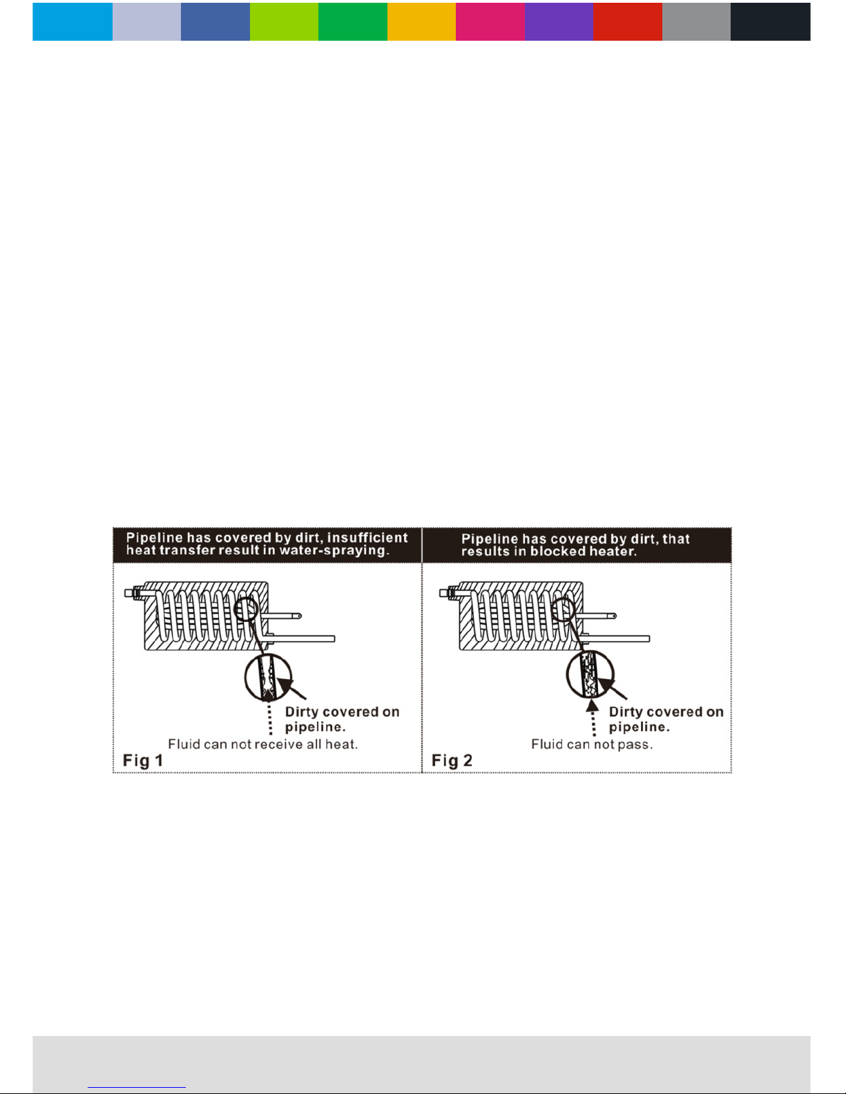
Oil injection trouble:
Refers to the fog uid atomizing in the heater pipe of the machine is not good, heater temperature cannot be timely and eective transmit
to the fog uid, fog uid cannot all atomization and lead to oil injection.
1. Using the low quality or counterfeit fog uid, low quality fog uid have more impurities, easy to adhere to the pipe wall and hindered
temperature transmission result in incomplete atomization caused oil injection.
2. Using an incorrect fog uid. Dierent fog uid have dierent required atomization temperature. If you use the wrong fog uid result in
oil cannot fully atomization caused oil injection.(g 1)
Heater blocking trouble:
Poor atomization oil injection is the early signs of heater block. Using poor quality fog uid or not timely maintenance cleaning the fog
machine for a long time. Inevitable will appear the terminal symptom of heater blocking.
1. heater blocked is because used inferior fog uid or not maintenance for a long time. Have nothing to do with the quality of machine.
Like a car with poor quality gasoline produce poor oil circuit failure or long-time no maintenance the car will inevitably appear bigger
problems. (g 2)
Solutions to these problems:
Fog machine heating pipes used for a long time and then the pipe wall will easily produce sediments (The more inferior fog uid the more
impurities thus lead to oil injection or blocked). All fog machines need regular maintenance (fog machine maintenance cycle for 1 to 2
months/time).
Specic maintenance method: after heating the 35% white vinegar plus 65% distilled water and then spray 10 to 15 times.
Conclusion:
As long as the fog machine with oil injection or heater blocking after using a period of time. It was caused by fog uid quality or lack of
maintenance, has nothing to do with the quality of the machine. Please use the original high quality fog uid and timely maintain it, then it
can be used for a long time
WWW.CLF-LIGHTING.COM
11
specif
i
cations
Power 3100W
LED LED bottom smoke: 9 PCS RGB
LED top smoke: 23 PCS RGB
Voltage / frequency AC100V - 240V - 50/60Hz
Fuse 15A/250V
Power consumption;
all eects static, zero light output <25W
AC power input PowerCON
DMX data in/out 5 pin & 3 pin locking XLR
Netto weight 16kg
Size 475x401x205mm
Control DMX & Wireless
Channel 11 channels
Output 54000CUFT/MIN (max 10m height and max 8 sec)
Settings and addressing Control panel with backlit LED graphic display
Protocol USITT DMX512-A & Wireless
Color Black
Housing High strenght die-casting aluminium and metal
Protection rating IP20
Orientation Up and downwards (when fuel tank is rotated)
Min. distance to combustable materials 100mm from machine
Min. distance to iluminated surfaces 200mm from machine
Wireless remote 4 button remote
Fluid consumption 3,7min/L
Fluid capacity 2,5L
Fluid brand CLF Fog uid
Heat up time 4 min
Max. ambient temperature (Ta max) 45°C

WWW.CLF-LIGHTING.COMCLFLIGHTING
ef smoke 3100
Table of contents


