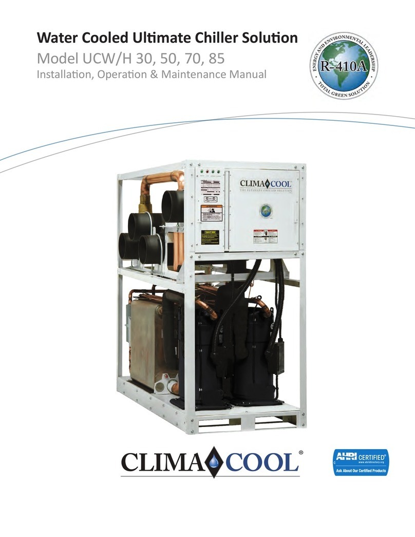
ClimaCool UCA 20 User manual

Packaged Air Cooled Modular Chiller
Water Cooled, Heat Pump, Heat Recovery and
^ŝŵƵůƚĂŶĞŽƵƐ,ĞĂƟŶŐĂŶĚŽŽůŝŶŐ,ĞĂƚWƵŵƉ
Model UCA 20, 30, 50 & 70
/ŶƐƚĂůůĂƟŽŶKƉĞƌĂƟŽŶΘDĂŝŶƚĞŶĂŶĐĞDĂŶƵĂů
on
DEMAND®
SIMULTANEOUS HEATING AND COOLING

Introduction.........................................1
Pre-Installation.......................................2
PhysicalData....................................... 3-5
DimensionalDataandDrawings......................6-8
RiggingandLiftingProcedures.........................9
MountingRailandVibrationIsolation..................10
RecommendedServiceClearances..................... 11
ModelKey..........................................12
UnitInstallation...................................13-14
ElectricalConnection.................................15
WiringDiagram-Voltage/PhaseMonitor ................16
WaterPiping......................................17-18
Ƥ ..........................19
HydronicRefrigeration...............................20
PartLoadPerformanceAdvantage .................... 21
FillingtheWaterSystem..............................22
WaterTreatment....................................23
WaterTemperatureRequirements.....................24
EvaporatorWaterPressureDropCharts.............25-26
Operational Limitations ..............................27
Pre-Startup.........................................28
Pre-StartupCheckList................................29
Startup.......................................... 30-31
Superheat&SubcoolingFlowChart....................32
StartupandWarrantyForm...........................33
OperationandMaintenance ..........................34
CondenserFans.....................................35
HeatExchangers ....................................36
CleaningArrangement ...............................37
CompressorInformation .............................38
RefrigerationCircuitDiagram ...................... 39-41
HeadPressureControlValveOperation(LAC)...........42
RefrigerationSystemsRe-ProcessingandCharging......43
Ƥ ...................44-45
Options&Accessories ...............................46
StainlessSteelStrainerOption ..................... 47-51
WYEStrainers.................................... 52-53
BasketStrainers..................................54-55
ElectricalData....................................56-57
PowerDistributionDrawing...........................58
WiringDiagrams..................................59-87
TroubleshootingGuide...............................88
Warranty...........................................89
Table of Contents

1
R
R
www.climacoolcorp.com
General Description
ClimaCool’sAir Cooled Packaged Modular Chiller, Model
UCA, are available in 20, 30, 50 and 70 tons and can be
Ƥ
requirements from 20 to 420 tons. By simply adding
modules, the UCA can satisfy future incremental growth
needs. This model is a quiet, serviceable and extremely
ƥǤ
Safety
Throughout this manual warning, danger, caution and
attention notices appear. Read these items carefully before
attempting any installation, service or troubleshooting
of the equipment. All labels on unit access panels must
be observed.
WARNING: Indicates potentially hazardous situation which,
ǡǤ
DANGER: Indicates an immediate hazardous situation
ǡǡǤ
CAUTION: Indicates a potentially hazardous situation or an
unsafe practice which, if not avoided, could result in minor
Ǥ
ATTENTION: Ƥǡ
maintenance information which is important, but not
hazard related.
Introduction
If this unit uses a 3 Phase Scroll
Compressor, the following
instructions MUST BE followed:
• Unit power supply MUST BE
wired in the proper sequence to
avoid damage to the 3 Phase
Scroll Compressor;
• Scroll Compressors with
INCORRECT rotation show the
following characteristics:
- High sound level;
- High suction pressure and
low discharge pressure;
- Low current draw.
• If any of the three above
characteristics exist, swap two of
the three supply wires at the
disconnect and recheck
compressor for incorrect rotation.
Si cet appareil utilise
compresseur scroll 3-Phase, les
instructions suivantes doivent être
suivies:
• L’alimentation de l’appareil doit
être monté dans l’ordre correct
pour éviter endommager le
compresseur scroll 3-Phase
• Compresseurs scroll avec
rotation incorrecte montrent les
caractéristiques suivantes:
- Haut niveau de son;
- Pression d’aspiration élevée
et une faible pression de
décharge;
- Faible ampérage
• Si l’un des trois éléments
mentionnés ci-dessus sont
remplies , échanger deux des
trois lignes électriques alimen
tant la interrupteur de sécurité et
YpUL¿HUODURWDWLRQGX
compresseur.
3 PHASE SCROLL
COMPRESSOR UNITS UNITÉ DE COMPRESSEUR
SCROLL 3-PHASE
CAUTION/ATTENTION
CAUTION/ATTENTION
Excessive Chlorine,
undissolved solids and other
improper water conditions
WILL DAMAGE the internal
heat exchanger & WILL VOID
YOUR WARRANTY!
Chlore excessive, solides non
dissous et les autres impropre
conditions de l’eau,
ENDOMMAGERA l’échangeur
de chaleur interne et
ANNULERA VOTRE
GARANTIE!
Very Hot Water! L’eau Trés Chaude!
WARNING/AVERTISSEMENT
CAUTION/ATTENTION
Use only copper conductors
IRU¿HOGLQVWDOOHGZLULQJ8QLW
terminals are not designed to
accept other types of
conductors.
Utilisez uniquement des
conducteurs en cuivre pour le
câblage. Bornes de l’unité ne
sont pas conçus pour
accepter d’autres types de
conducteurs.
Disconnect power supply
(ies) before servicing. Refer
VHUYLFLQJWRTXDOL¿HGVHUYLFH
personnel. Electric shock
hazard. May result in injury
or death!
Unit to be serviced by
TXDOL¿HGSHUVRQQHORQO\
Refrigerant system under
pressure. Relieve pressure
before using torch. Recover
refrigerant and store or
dispose of properly.
Debrancher avant d’entre-
prendre le dépannage de
l’appareil. Consulter un
UpSDUDWHXUTXDOL¿HSRXUOH
dépannage. Risque de choc
électrique. Résiltat de mai
dans dommages ou la mort!
Conifer la maintenance à
XQWHFKQLFLHQTXDOL¿H/H
V\VWpPHIULJRUL¿TXHVRXV
pression. Décomprimer avant
G¶H[SRVHUjODÀDPPH
Récuperer le frigorigene et
le stocker ou le détrulre
correctement.
WARNING/AVERTISSEMENT
CAUTION/ATTENTION
WARNING/AVERTISSEMENT
W
W
W
WATER AND REFRIGERANT
SYSTEMS UNDER PRESSURE
• Isolate/Lockout source
and relieve pressure
BEFORE servicing
equipment.
• Failure to relieve pressure
may result in property
damage, serious bodily
injury or death!
EAU ET FRIGORIGÈNE
EQUIPEMENTS SOUS
PRESSION
• Isoler la source / de
verrouillage et de
soulager la pression
avant entretien de l’équi-
pement.
• Le défaut de soulager la
pression peut entraîner
des dommages matériels,
des blessures corporelles
graves ou la mort!
ATTENTION
To avoid the release of refrigerant into the atmosphere, the
refrigerant circuit of this unit must be serviced only by
WHFKQLFLDQVZKRPHHWORFDOVWDWHDQGIHGHUDOSUR¿FLHQF\
requirements.
All refrigerant discharged from this unit must be recovered
WITHOUT EXCEPTION. Technicians must follow industry
accepted guidelines and all local, state and federal statues for
the recovery and disposal of refrigerants.
If a compressor is removed from the unit, system refrigerant
circuit oil will remain in the compressor. To avoid leakage of
compressor oil, the refrigerant lines of the compressor must be
sealed after it is removed.
Do not defeat, cap, add piping to the outlet of the
valve or attempt to change the relief setting.
ATTENTION
&RQ¿UPDOOSDQHOVDQGHOHFWULFDOFRYHUVDUH
properly installed/sealed, including the condenser
fan motor cover.
ATTENTION
CAUTION/ATTENTION
Single wall heat
exchanger, not suitable
for potable water
connection.
Single paroi echangeur,
non approprié pour le
raccordement d'eau
potable.

R
R
www.climacoolcorp.com
2
Inspection
Upon receipt of equipment, carefully check the shipment
against the bill of lading and inspect each chiller for
any damage incurred during shipment. Thoroughly
check for any visible damage of control panels, electrical and/
or refrigeration components or broken copper lines. Be sure
the nameplate voltage agrees with the site voltage. The carrier
must make proper notation of any damages or shortages
on all copies of the bill of lading and complete a common
Ƥ
shipment. Note:Ƥ
all necessary claims with the carrier. In addition, please
notify the ClimaCool Customer Service Department at
all damage immediately.
Storage
Installation and storage of Packaged Air Cooled chillers, in locations
with ambient temperatures below 40°F, will require a suitable
antifreeze solution.
Handling of Modules
Carefully remove the module’s packaging. The chiller’s steel
base cutouts provide maneuverability by forklift or pallet
Ƥȋ
Figures 7, 8 and 9 on page 9). Verify that all header grooved
couplings, groove by groove 6” nipples and mounting hardware
kits are on site prior to connecting the modules.
Rigging and Lifting
Each module should be lifted by using a fork lift. If it is
necessary to utilize a crane for rigging or lifting each module
shall be lifted by using lifting straps and spreader bars using
Ƥ
on page 9.
Warranty
To ensure proper equipment longevity, design performance
and reliability, all ClimaCool chillers must be installed, operated
and maintained in accordance with ClimaCool IO&M manuals.
Water quality is of the utmost importance for the proper
care and maintenance of your modular chiller system and
regular treatment of the water will increase longevity of your
system. Ƥ
evaporator water will void the ClimaCool module’s warranty.
A factory authorized technician is required to perform the
startup of your ClimaCool chiller. Please contact the ClimaCool
Service Department at 405-815-3000 or at technicalsupport@
climacoolcorp.com to schedule. There is a minimum of (three)
3 weeks notice required to schedule your factory startup.
Pre-Installation

3
R
R
www.climacoolcorp.com
Physical Data
1
20 30 20 30 20 30
18.4 27.5 17.9 26.7 17.9 26.7
EER 10.3 10.3 9.97 9.97 9.97 9.97
22 2 2 2 2
scroll scroll scroll scroll scroll scroll
2222 22
10 15 10 15 10 15
50 56 50 54 50 54
2,250 2,410 2,250 2,410 3,115 3,275
2,035 2,195 2,035 2,195 2,735 2,895
20 30 20 30 20 30
T.E. T.E. T.E. T.E. T.E. T.E.
HP 2.0 2.0 2.0 2.0 2.0 2.0
1212 12
Fan Type Axial Axial Axial Axial Axial Axial
Diameter 31.5" 31.5 31.5" 31.5 31.5" 31.5
Airflow (cfm per circuit) 6000 9,800 6000 9,800 6000 9,800
RPM 1,100 1,100 1,100 1,100 1,100 1,100
650 650 650 650 650 650
20 30 20 30 20 30
Fin Material Aluminum Aluminum Aluminum Aluminum Aluminum Aluminum
Tube Material Copper Copper Copper Copper Copper Copper
Dimensions (Quantity) 22" x 78" (4) 22" x 78" (4) 22" x 78" (4) 22" x 78" (4) 22" x 78" (4) 22" x 78" (4)
Rows Deep 34 3 4 3 4
Fins Per Inch 12 12 12 12 12 12
20 30 20 30 20 30
Brazed Plate Brazed Plate Brazed Plate Brazed Plate Brazed Plate Brazed Plate
2222 22
2.6 2.6 2.6 2.6 2.6 2.6
39.6 39.6 39.6 39.6 76.6 76.6
300 300 300 300 300 300
6" 6" 6" 6" 6" 6"
Notes:
1. SHC - Simultaneous Heating and Cooling Heat Pump
2. Unit tonna
g
e ARI ratin
g
conditions: 44°F leavin
g
chilled water temperature, 95°F enterin
g
condenser air temprature, flow rate is
2.4 GPM per ton throu
g
h the evaporator with a .0001 foulin
g
factor.
3. Module operational wei
g
ht includes water, compressor oil, and refri
g
erant char
g
e. Multiply times the number of modules for a
total system operational wei
g
ht.
4. Unit shippin
g
wei
g
ht includes refri
g
erant char
g
e, compressor oil and packa
g
in
g
; based on transportation.
5. Main header water/fluid connections are ASME, 6" scheduled 40 pipe with
g
rooved couplin
g
s, 300 psi
g
manimum workin
g
pressure.
6. Each refri
g
erant circuit is capable of providin
g
reliable operation down to 20°F ambient with proper freeze protection.
Condenser Fans
Evaporator
Maximum Design Working Pressure - Water Side (PSI)
Model UCA
Condenser Coils
Cooling Only Heat Pump
Header Water Connections - Inlet/Outlet (inches)5
Maximum Design Working Pressure - refrigerant (PSI)
Heat Exchanger (Type)
Independent Refrigerant Circuits (quantity)
Water Storage Volume HX Only (gals.)
Module Shipping Weight (lbs)΄
Water Storage Volume HX Plus 6" Main Headers (gals)
SHC1
Compressor Quantity
Compressor Nominal Hp (per circuit)
Refrigerant Charge R-410A (lbs)
Module Operating Weight w/Water (lbs)³
Quantity
Motor Type
Capacity (Tons)2
Refrigerant Circuits (quantity)
Compressor Type
.

R
R
www.climacoolcorp.com
4
Physical Data
Model UCA
50 70 50 70 50 70
Capacity (Tons)244.0 62.7 41.4 59.0 41.4 59.0
Efficincy (EER)210.5 10.1 9.88 9.47 9.88 9.47
Refrigerant Circuits (quantity) 2.0 2.0 2.0 2.0 2.0 2.0
Compressor Type Scroll Scroll Scroll Scroll Scroll Scroll
Compressor Quantity 222222
Compressor Nominal Hp (per circuit) 25 35 25 35 25 35
Refrigerant Charge R-410A (lbs) (circuit 1/circuite2) 114 124 110 120 110 120
Module Operating Weight w/Water (lbs)³ 4,101 4,275 4,101 4,275 4706 4880
Module Shipping Weight (lbs)΄3,855 4,005 3,855 4,005 4,255 4,405
Condenser Fans 50 70 50 70 50 70
Motor Type T.E. T.E. T.E. T.E. T.E. T.E.
HP 1.5 1.5 1.5 1.5 1.5 1.5
Quantity 444444
Fan Type Axial Axial Axial Axial Axial Axial
Diameter 31.5 31.5 31.5 31.5 31.5 31.5
Airflow (cfm per circuit) 7,000 10,500 7,000 10,500 7,000 10,500
Max RPM 1,100 1,100 1,100 1,100 1,100 1,100
Maximum Design Working Pressure - refrigerant (PSI) 650 650 650 650 650 650
CondenserCoils 507050705070
Fin Material Aluminum Aluminum Aluminum Aluminum Aluminum Aluminum
Tube Material Copper Copper Copper Copper Copper Copper
Dimensions (Quantity) 22" x 78" (8) 22" x 78" (8) 22" x 78" (8) 22" x 78" (8) 22" x 78" (8) 22" x 78" (8)
Rows Deep 444444
Fins Per Inch 12 12 12 12 12 12
Evaporator 50 70 50 70 50 70
Heat Exchanger (Type) Brazed Plate Brazed Plate Brazed Plate Brazed Plate Brazed Plate Brazed Plate
Independent Refrigerant Circuits (quantity) 222222
Water Storage Volume HX Only (gals.) 4.9 7.7 4.9 7.7 4.9 7.7
Water Storage Volume HX Plus 6" Main Headers (gals) 43.5 48.4 43.5 48.4 43.5 48.4
Maximum Design Working Pressure - Water Side (PSI) 300 300 300 300 300 300
Header Water Connections - Inlet/Outlet (inches)² 6" 6" 6" 6" 6" 6"
Cooling Only Heat Pump SHC
Notes:
1. SHC - Simultaneous Heatin
g
and Coolin
g
Heat Pump
2. Unit tonna
g
e and efficiency at AHRI ratin
g
conditions: 44°F leavin
g
chilled water temperature, 95°F enterin
g
condenser air temprature, flow rate is
2.4 GPM per ton throu
g
h the evaporator with a .0001 foulin
g
factor.
3. Module operational wei
g
ht includes water, compressor oil, and refri
g
erant char
g
e. Multiply times the number of modules for a
total system operational wei
g
ht.
4. Unit shippin
g
wei
g
ht includes refri
g
erant char
g
e, compressor oil and packa
g
in
g
; based on transportation.
5. Main header water/fluid connections are ASME, 6" scheduled 40 pipe with
g
rooved couplin
g
s, 300 psi
g
manimum workin
g
pressure.
.

5
R
R
www.climacoolcorp.com
Physical Data
30 70
T.E. T.E.
HP 2.0 2.0
24
Fan Type Axial Axial
Diameter 31.5 31.5
Airflow (cfm per circuit) 20,000 40,000
RPM 1,100 1,100
30 70
Fin Material Aluminum Aluminum
Tube Material Copper Copper
Dimensions (Quantity) 20" x 78" (4) 20" x 78" (8)
Rows Deep 66
Fins Per Inch 88
30 70
300 300
6" 6"
2,000 4,000
1,590 3,180
Notes:
1. Module operational weight includes water. Multiply times the number of modules for a
total system operational weight.
2. Unit shipping weight includes packaging; based on transportation.
Module Shipping Weight2
Free Cooling Coils
Free Cooling Free Cooling
Module Operating Weight 1
Header Water Connections - Inlet/Outlet (inches)
Quantity
Motor Type
Fans
Miscellaneous Information
Maximum Design Working Pressure - Water Side (PSI)

R
R
www.climacoolcorp.com
6
Dimensional Data and Drawings
Model
UCA Voltage A
Unit Width
(in.)
B
Unit Height
(in.)
C
Unit Depth
(in.)
D
Header
Location
(in.)
E
Header
Location
(in.)
Header
Connection
(in.)
020 208/230/460/575/3/60 Ψ 92 Ψ ΨΟΞ ·ΨΟΞ 6
030 208/230/460/575/3/60 Ψ 92 Ψ ΨΟΞ ·ΨΟΞ 6
Model
UCA1Voltage A
Unit Width
(in.)
B
Unit Height
(in.)
C
Unit Depth
(in.)
D
Header
Location
(in.)
E
Header
Location
(in.)
F
Header
Location
(in.)
Header
Connection
(in.)
050 208/230/460/575/3/60 Ψ ΨΦ ΨΠ ΨΟΞ ·ΨΟΞ ΄ΨΣ 6
070 208/230/460/575/3/60 Ψ ΨΦ ΨΠ ΨΟΞ ·ΨΟΞ ΄ΨΣ 6
Note:
1. The model UCA 050 and 070 cannot be coupled back-to-back.
Control
Box
B
A
Air
Discharge
Figure 1 - Cooling Only, UCA 020 & 030
Figure 2 - Cooling Only, UCA 050 & 070
Air
Discharge
Control
Box
B
A
Air
Discharge
C
D
E
F
Air
Intake Air
Intake
Air
Intake Air
Intake
Chilled
Water
Inlet
Chilled
Water
Outlet
Air Intake
Air Intake
C
D
E
Air
Discharge
Chilled
Water
Outlet
Chilled
Water
Inlet

7
R
R
www.climacoolcorp.com
Dimensional Data and Drawings
Notes:
1. All SHC models cannot be coupled back-to-back.
Model
UCA1Voltage A
Unit Width
(in.)
B
Unit Height
(in.)
C
Unit Depth
(in.)
D
Header
Location
(in.)
E
Header
Location
(in.)
F
Header
Location
(in.)
G
Header
Location
(in.)
Header
Connection
(in.)
020 SHC 208/230/460/575/3/60 Ψ 92 ΨΠ ΨΟΞ ·ΨΟΞ ΄ΨΣ ΨΣ 6
030 SHC 208/230/460/575/3/60 Ψ 92 ΨΠ ΨΟΞ ·ΨΟΞ ΄ΨΣ ΨΣ 6
Model
UCA1Voltage A
Unit Width
(in.)
B
Unit Height
(in.)
C
Unit Depth
(in.)
D
Header
Location
(in.)
E
Header
Location
(in.)
F
Header
Location
(in.)
G
Header
Location
(in.)
Header
Connection
(in.)
050 SHC 208/230/460/575/3/60 Ψ ΨΦ ΨΠ ΨΟΞ ·ΨΟΞ ΄ΨΣ ΨΣ 6
070 SHC 208/230/460/575/3/60 Ψ ΨΦ ΨΠ ΨΟΞ ·ΨΟΞ ΄ΨΣ ΨΣ 6
Figure 3 - Simultaneous Heating & Cooling 020 & 030
Figure 4 - Simultaneous Heating & Cooling 050 & 070
A
B
Air
Discharge
Control
Box
Air
Discharge
Air Intake
Air Intake
C
D
FG
E
Chilled
Water
Inlet
Chilled
Water
Outlet Hot
Water
Outlet
Hot
Water
Inlet
Air
Discharge
B
A
Control
Box
Air
Discharge
Air
Discharge
Air
Intake Air
Intake
Air
Intake Air
Intake
Chilled
Water
Inlet
Hot
Water
Outlet
Hot
Water
Inlet
Chilled
Water
Outlet
C
D
E
FG

R
R
www.climacoolcorp.com
8
Model
UCF Voltage
A
Unit Width
(in.)
B
Unit Height
(in.)
C
Unit Depth
(in.)
D
Header
Location
(in.)
E
Header
Location
(in.)
F
Header
Location
(in.)
Header
Connection
(in.)
030 208/230/460/575/3/60 Ψ 92 Ψ ΨΟΞ ·ΨΟΞ ΄ΨΣ 6
Model
UCF1Voltage
A
Unit Width
(in.)
B
Unit Height
(in.)
C
Unit Depth
(in.)
D
Header
Location
(in.)
E
Header
Location
(in.)
F
Header
Location
(in.)
Header
Connection
(in.)
070 208/230/460/575/3/60 Ψ ΨΦ ΨΠ ΨΟΞ ·ΨΟΞ ΄ΨΣ
6
Dimensional Data and Drawings
Figure 5 - Free Cooling, UCF 030
Figure 6 - Free Cooling, UCF 070
Air
Discharge
B
A
Control
Box
C
Air
Intake
Air
Intake
Air
Intake
Air
Intake E
F
D
Chilled
Water
Inlet
Chilled
Water
Outlet
Air
Discharge
Air Intake
Air Intake
C
E
F
D
Chilled
Water
Inlet
Chilled
Water
Outlet
B
A
Control
Box
Note:
1. The model UCF 070 cannot be coupled back-to-back.

9
R
R
www.climacoolcorp.com
Lifting and Transporting Modules
Forklifts are required for lifting and transporting the
module. Each module has base cutouts provided
for ease of maneuverability.
Rigging
Each module should be lifted by using lift straps threaded
through the steel base cutouts and a spreader bar.
Note: If no spreader bar is used, damage to the module
may occur.
Figure 7
Spreader Bar
Spreader Bar
Lifting Strap
Figure 9
Spreader Bar
Lifting Strap
Figure 8
Rigging and Lifting Procedures

R
R
www.climacoolcorp.com
10
4” Rail Minimum
Recommended
(by others)
Concrete Pad (by others)
4” Rail Minimum
Recommended
(by others)
Spring Vibration
Isolators (by others)
Concrete Pad (by others)
Figure 11 - Spring Vibration Iolators Option
ZĞĐŽŵŵĞŶĚĞĚŶĐŚŽƌ>ŽĐĂƟŽŶƐ
0.563” Hole Diameter Typ. 0.56” Typ.
Base Rails
2.19”
81.38”81.38”
3.25”
170.5”
2.19”
36”
1.75”
1”
Figure 12 - Vibration Isolation Pads Option
Concrete Pad (by others)
Figure 10 - Support Rails and Anchor Locations
Figure 11 - Spring Vibration Isolators Option
ClimaCool recommends locking down the chiller to a concrete base or to two (2) 4” base mounting rails using the six bolt
holes provided in each base pan (see Figure 10). Due to the low vibration of the modules, ClimaCool does not require the
application of spring isolators or pads. Should isolators or pads be desired, install in accordance with Figures 11 and 12.
Mounting Rail and Vibration Isolation
Note:ƤǤ

11
R
R
www.climacoolcorp.com
Recommended Service Clearances
Notes:
ǤȀǡǦǦƤdzdz
clearance for rear service access.
ǤȀǡǦǦƤdzǤ
ǤǡǦǦƤdz
service and air intake sides.
ǤƪǤ
5. Local building or electrical codes may require additional clearance. Consult applicable codes.
ǤƤǤ
Rear Service Access
Air Intake Air Intake
Service and Air Intake
Clearance
Top View
See Note
4 for side
clearance
See Note
4 for side
clearance
See Note
4 for side
clearance
See Note
4 for side
clearance
Air Intake
Air Intake
Service and Air Intake
Clearance
Service and Air Intake
Clearance
ǦǦǦƤ
ǦǦǦƤ
36” 36”
42”
42” 42”
42”42”

R
R
www.climacoolcorp.com
12
Model Key
RejectionMeans
A=AirCooledPackage(Outdoor) ModelConfiguration
F=FreeCoolingModule B=BirdScreen
(Availablein30&70Tononly) C=CondenserCoilGuard
D=CoatedCondenser
E=CoatedCondenserwithCoilGuard
NominalTons F=CondenserCoilHailGuard
020(N/AforFreeCoolingModule) G=HeaderlessModulewithCondenserCoilGuard
030 H=HeaderlessModule
050(N/AforFreeCoolingModule) I=CoatedCondenserwithBirdScreen
070 J=CoatedCondenserwithHailGuard
K=HeaderlessModulewithCondenserHailGuard
DesignSeries L=HeaderlessModulewithCondenserCoilCoating
AN=HeaderlessModulewithCondenserCoilCoatingandHailGuard
BP=HeaderlessModulewithCondenserCoilCoating,HailGuardandBirdScreen
R=CoatedCondenserwithHailGuardandBirdScreen
Voltage S=Standard
F=460/3/60 T=HeaderlessModulewithCondenserHailGuardandBirdScreen
H=208Ͳ230/3/60 U=HeaderlessModulewithCoatedCondenserandBirdScreen
N=575/03/60 Y=CondenserCoilHailGuardwithBirdScreen
U=380/3/50 Z=HeaderlessModulewithBirdScreen
RefrigerantOptions
Controls&Electrical 0=NoneͲStandardLowAmbientto0°F
A=StandardControls B=HotGasBypassͲBothCircuits
S=SingleModuleControls M=LowAmbienttoͲ20°FwithHotGasBypassͲBothcircuits
T=SingleModuleControlswithLonWorks N=LowAmbienttoͲ20°F
WaterIsolationValves
0=(None)
CompressorType E=Evap.MotorizedValves&ManualCondsrValves
0=(None)(lessManualCondsrValvesforAirCooled)
F=ScrollwithFullHeightVenturi M=ManualValvesforEvap&Condsr
S=Scroll (lessManualCondsrValvesforAirCooled)
Application
Refrigerant 0=(None)
0=(None)C=Cooling
A=RͲ410A H=HeatRecovery(Desuperheater)
R=ReverseCycle(HeatPump)
S=SimultaneousHeating&CoolingHeatPump(4headers)
Ј ІЈ ІЉ
00
ІЇІІ
UltimateChillerSolutionModelKey
ІЊ
AASACB
ІЇ
UC F S
ЍЉЊЋ Ќ Ў ІЅ
020

13
R
R
www.climacoolcorp.com
Foundation for Unit Placement
The minimum foundation requirement for the ClimaCool
chiller is a level surface capable of bearing the combined
operating weight of the modules (See Physical Data -
page 3-5).
Service Access
Recommended Service Clearances and Bank Dimensions
shown on page 11.
Draining
When performing standard maintenance procedures such
ƪǡ
ơǤơ
optional water isolation valves for this purpose.
Assembling Modules
ClimaCool recommends locking down the chiller to a
concrete base, or to two (2) 4” base mounting rails using
the bolt holes provided in the unit base. Although the
compressors are installed on anti-vibration mountings,
further isolation of the chiller from the structure is
available by installing vibration eliminating springs or
pads under the base rails on which the chiller will rest
(See page 10 – Mounting Rail and Vibration Isolation).
One end of the modules should be chosen as the reference
module and carefully located.
Field installed mounting accessories are provided for
Ǥ
• Header grooved coupling kits containing two (2) for
water cooled and heat pump applications and four (4)
for simultaneous heat pump applications.
• Mounting hardware kit containing necessary bolts,
spacers, nuts and washers.
• Header bank end cap kit containing two (2) each for
water cooled and heat pump and four (4) each for
simultaneous heat pump applications.
• Groove by groove 6” nipples, one (1) required
per header.
Field installing the mounting hardware kit will assist
with alignment of the modules in a bank and eliminate
ơǤǡ
show the end to end and back to back holes for the 1”
spacers between the units. The spacers will allow for an 1”
separation between modules in both the end to end and
ƤǤ
Once the spacers are installed, the distance from the
post upright will be 1”. Using the appropriate tools tighten
hardware assembly until seated.
Inspect the pipe ends to ensure they are free from any
ǡǡ
surface defects such as loose paint, scale, dirt, chips,
grease and rust. Inspect the grooved coupling gasket
for any defects. Apply a thin layer of silicone or other
non-petroleum lubricant to the sealing lips of the gasket
and to the exterior of the gasket. Install gaskets on the pipe
ends of one of the two modules to be mated. Be sure the
gasket is completely on the pipe so damage will not occur
in the next step.
One groove by groove 6” nipple per header is required to
complete the connection between each module. Move the
second module into position and line up the piping. Ensure
you are maintaining alignment for any additional modules to
be added. When pipe ends are aligned, slide the gasket over
the ends and center it between the grooves. No part of the
gasket should protrude into the groove of either pipe end.
Place the coupling halves over the gasket and make sure
that the coupling keys, (the part that goes into the groove),
are engaged into the grooves. Insert the bolts and install
nuts to hand tight. Make sure that the oval neck of the bolt
engages into the bolt hole of the housing. Tighten nuts
alternately and equally until the bolt pads meet and make
metal to metal contact. Tighten nuts by another 1/4 to 1/2
turn to make sure the nuts and bolts are snug and secure;
the use of a torque wrench is usually not required. Uneven
tightening of bolts may cause the gasket to be pinched
resulting in immediate or delayed leaks.
Assembling Modules Back to Back
Ƥǡ
Figure 17.
• dzƪ
header-less unit.
• Loosen the lower 2” grooved coupling from the bottom
header and remove the end cap.
• Lubricate the rubber gasket with approved grooved
coupling lubricant.
• ƪǦ
unit into the 2” grooved coupling on the header where
the end-cap was previously removed.
• Equally tighten the 2 bolts to 15 to 22 ft-lbs of torque.
• Repeat above procedure for the upper
hose connection.
Unit Installation

R
R
www.climacoolcorp.com
14
Header Insulation
Chilled water piping is pre-insulated on each module at
the factory with 3/4” closed cell insulation. After bolting
all modules together and leak testing, the entire coupling
connection will need to be insulated by the installing
contractor.
Access Panels
ƥǡ
ǡ
and always prior to operation of the bank. Lower side acess
panels are available as an option.
Unit Installation
Figure 17 - Back to BackFigure 15 - Hardware Kit
Figure 16 - Spacer Holes
END TO END SPACER HOLES
BACK TO BACK SPACER HOLES

15
R
R
www.climacoolcorp.com
Proper Voltage Balance
Occasionally, in three phase circuits, a voltage imbalance
occurs between phases. It is not recommended to operate
equipment when an imbalance greater that 2% occurs. This
ơ
their longevity. The following example describes how to
calculate the average voltage of the three phases to see if
the imbalance is greater than 2%.
Example: Line 1 = 226v Line 2 = 230v Line 3 = 228v
The average is: (226+230+228)/3 = 228v
Next, [100(228-226)]/228 = 0.9%
The voltage imbalance of the three phase circuit is 0.9%.
This is well under the 2% range.
Voltage/Phase Monitor
ȀƤ
installation with the CoolLogic Master Control Panel. The
voltage/phase monitor helps guard the chiller bank against
ƪǡ
conditions which could void your warranty. The voltage/
phase monitor has three wires that connect to the main
three phase power chiller bank input. Two low voltage
control wires are connected to the CoolLogic Master Control
Panel. Do not install control wiring in the same conduit as
line voltage wiring or with wires that switch highly inductive
loads such as contactor and relay coils. Note: It is mandatory
to install one (1) monitor per bank at main power
distribution panel to monitor voltage and phasing of power
to the modules. See Wiring Diagram on page 16.
The power for modules is taken from a suitable circuit
breaker/fused disconnect power supply within the main
panel. The electrical service enters the individual modules
through the upper right side of the module’s control panel
enclosure. Proper grounding of the module is mandatory.
ǡƤ
main supply is isolated. A typical power wiring is located on
page 55 – Power Distribution Drawing. Knockout drawings
are provided. Do not drill into cabinet; shavings can damage
electronic components. The power for all individual modules
shall be in compliance with all local and national codes.
CoolLogic Control System Wiring
A separate 115 volt power supply is required to power the
CoolLogic Master Control Panel. Communication between
the Master Controller and chiller modules requires a simple
two-conductor, 18 AWG shielded cable rated at 60°C
minimum, daisy chain connection. Control wiring cannot be
installed in the same conduit as line voltage wiring or with
wires that switch highly inductive loads such as contactor
and relay coils. Refer to the Power Distribution schematic on
page 52 and Wiring Diagrams on pages 82-84 of this manual
for more information. All wiring shall be in compliance with
all local and national codes.
Electrical Phase Sequencing
Proper clockwise rotation for scroll compressor motors is
important to prevent damaging the compressors. ClimaCool
recommends the use of a phase sequence indicating
instrument following the manufactures directions. Another
alternative would be to “bump test” the compressors one
at a time with pressure gauges attached to the high and
low gauge ports of the compressors to check for proper
rotation. Energize the compressor for a few seconds to
ƤǤ
If the discharge pressure does not increase, proper rotation
is reversed. Compressor rotation can be reversed by
opening the main electrical disconnect and switching
any two of the main power supply leads feeding that
compressor’s contactor.
Electrical Connection
If this unit uses a 3 Phase Scroll
Compressor, the following
instructions MUST BE followed:
• Unit power supply MUST BE
wired in the proper sequence to
avoid damage to the 3 Phase
Scroll Compressor;
• Scroll Compressors with
INCORRECT rotation show the
following characteristics:
- High sound level;
- High suction pressure and
low discharge pressure;
- Low current draw.
• If any of the three above
characteristics exist, swap two of
the three supply wires at the
disconnect and recheck
compressor for incorrect rotation.
Si cet appareil utilise
compresseur scroll 3-Phase, les
instructions suivantes doivent être
suivies:
• L’alimentation de l’appareil doit
être monté dans l’ordre correct
pour éviter endommager le
compresseur scroll 3-Phase
• Compresseurs scroll avec
rotation incorrecte montrent les
caractéristiques suivantes:
- Haut niveau de son;
- Pression d’aspiration élevée
et une faible pression de
décharge;
- Faible ampérage
• Si l’un des trois éléments
mentionnés ci-dessus sont
remplies , échanger deux des
trois lignes électriques alimen
tant la interrupteur de sécurité et
YpUL¿HUODURWDWLRQGX
compresseur.
3 PHASE SCROLL
COMPRESSOR UNITS UNITÉ DE COMPRESSEUR
SCROLL 3-PHASE
CAUTION/ATTENTION
CAUTION/ATTENTION
Use only copper conductors
IRU¿HOGLQVWDOOHGZLULQJ8QLW
terminals are not designed to
accept other types of
conductors.
Utilisez uniquement des
conducteurs en cuivre pour le
câblage. Bornes de l’unité ne
sont pas conçus pour
accepter d’autres types de
conducteurs.
Disconnect power supply
(ies) before servicing. Refer
VHUYLFLQJWRTXDOL¿HGVHUYLFH
personnel. Electric shock
hazard. May result in injury
or death!
Unit to be serviced by
TXDOL¿HGSHUVRQQHORQO\
Refrigerant system under
pressure. Relieve pressure
before using torch. Recover
refrigerant and store or
dispose of properly.
Debrancher avant d’entre-
prendre le dépannage de
l’appareil. Consulter un
UpSDUDWHXUTXDOL¿HSRXUOH
dépannage. Risque de choc
électrique. Résiltat de mai
dans dommages ou la mort!
Conifer la maintenance à
XQWHFKQLFLHQTXDOL¿H/H
V\VWpPHIULJRUL¿TXHVRXV
pression. Décomprimer avant
G¶H[SRVHUjODÀDPPH
Récuperer le frigorigene et
le stocker ou le détrulre
correctement.
WARNING/AVERTISSEMENT
CAUTION/ATTENTION

R
R
www.climacoolcorp.com
16
Wiring Diagram-Voltage/Phase Monitor

17
R
R
www.climacoolcorp.com
As with any water system, it is important that the system
be clean. The pipe work installer must remove weld scale,
rust and contamination during pipe work fabrication.
ƪ
ƪ
are compatible with 316 stainless steel prior to making
connections to the ClimaCool chiller. There are certain
necessary components that should always be installed in
the chilled water system. (See Figures 21 and 22 on page 19 -
ƤƤ
modules). All water piping must be installed in accordance
with applicable codes and standards.
Temperature Sensor and Wells
ClimaCool provides two (2) temperature sensors and
wells with each two pipe chiller system and four (4) with
simultaneous heating & cooling four pipe chiller systems
ƤCoolLogic Control System. They must
Ƥdzdz
away from the bank and before the strainer on the chilled
water inlet and chilled water outlet (See Water Piping
ƤȂȌǤNote: Sensors must be fully
inserted into the well to obtain proper readings. Use a
slender, blunt instrument to gently push the sensor to the
bottom of the sensor well.
ơ
ƪ
ǡƤ
26, are not exceeded. To prevent operation of the chiller
ƥƪǡ
ơƪ
the chilled water circuit. Place downstream of the strainer
on the outlet of a straight pipe, as close to the module
as possible. Do not put in an elbow on the outlet. When
ơǡ
sure to bleed any air from the tubing before tightening.
ȋƤȂȌǤ
Pressure Taps
The installing contractor must provide access ports for
ơƪ
sensors and pressure gauges for the chilled water system.
A 1/4” pressure tap is required on the inlet and the outlet
of the chilled water system for a total of four (4) taps
with each two (2) pipe chiller system and six (6) with each
simultaneous heating and cooling four pipe chiller system.
ơƪ
and the pressure gauge it will require two (2) 1/2” taps.
ȋƤȂȌǤ
Water Isolation Valves
It is recommended to provide bank water isolation valves for
proper isolation and maintenance of the chiller, pump and
ȋƤȂȌǤ
Strainers – Minimum 60 Mesh Screen Required
ClimaCool chillers utilize brazed plate heat exchangers
which are extremely sensitive to debris. Therefore, it is
mandatory that all chilled water systems include a strainer
ƤǤ
The strainer must be installed as shown in the Water Piping
Ƥ
when the chiller is operating. ClimaCool’s warranty does
not cover and does not apply to products which have
defects or damages due to freezing of the water supply,
an inadequate or interrupted water supply, corrosives or
abrasives in the water supply, or improper or inadequate
ƤǤ
Chiller/Heater System Water Header Bypass
A bypass is required for any load cooling, cooling only and
load cooling and load heating, simutaneous heating and
cooling heat pump with variable pumping. The chiller bank
bypass must be piped in such a way that the temperature
ơƪ
ƪǤȋƤȂȌǤ
The purpose of the chiller/heater system bypass is to
prevent deadheading of the pumps when all of the internal
unit valves go closed as well as allow temperature and
ơƪǤ
bypass should be sized for an absolute minimum of one
ǯƪǤȋ
ƪȌǤ
Ƥǡ
cooling, however, this limits the number of modules
remaining for that duty. Also, with a module acting as a
bypass increased wear of heat exchangers may be caused
ƪǤ
Water Piping
No. 29 Reducing Tee
w/Thd. Branch
6 x 6 x 2
END VIEW
No.10
2" 90°
Elbow
No.50 Reducer
6 x 2
Hose Kit
2" Belimo
Ball Valve &
Actuator
2"
Grooved
Coupling
No.10
2" 90° No.50
Reducer
6 x 2
Module
Header
No. 29 Reducing Tee
w/Thd. Branch
6 x 6 x 2
Module
Header
SIDE VIEW
6"
Groo ved Coupling
6"
Groo ved Coupling
2"
Grooved
Coupling
Hose Kit
2"
Grooved
Coupling
2" Belimo
Ball Valve &
Actuator
Figure 18 - Reverse Return

R
R
www.climacoolcorp.com
18
No. 25 Grooved Br anch
6 x 6 x 2
No. 29 Reducing Tee
w/Thd. Branch
6 x 6 x 2
END VIEW
Hose Kit
2" Belimo
Ball Valve &
Actuator
2"
Grooved
Coupling
No. 25 Grooved Br anch
6 x 6 x 2 Module
Header
6"
Groov ed Coupling
No. 29 Reducing Tee
w/Thd. Branch
6 x 6 x 2
Module
Header
6"
Grooved Coupling
SIDE VIEW
2" Belimo
Ball Valve &
Actuator
Hose Kit
2"
Grooved
Coupling
Figure 19 - Direct Return
Water Piping
Load Side System Bypass (Air Handlers, Fan
Coils, etc.)
A load system bypass is required for preventing pump
ǡƪ
ƪȀǤ
Examples of an acceptable load side system bypass are:
• Utilize a quantity of 3-way control valves on the largest
loads farthest from the chiller/heater system.
• Field piping with a control valve to provide a bypass
across the larger system loads when their 2-way valves
go closed.
Please refer to Figure 20 for a typical load bypass valve
arrangement. The load side system bypass should be sized
for an absolute minimum of one module’s worth of design
ƪǤȋƪ
rates). A minimum of (6) six gallons per nominal system ton
are also required to maintain proper system thermal inertia.
This is to avoid short cycling of compressors in the chiller/
heater system as well as prevent nuisance alarms.
LOAD 1
FROM CHILLER BANK
TO CHILLER BANK
LOAD ϮLOAD 3 LOAD X
Figure 20 - Typical Load Bypass Valve Arrangement
TYPICAL CHILLED AND HOT WATER
LOAD SIDE BYPASS VALVES
SIZE EQUIVALENT TO ONE MODULE
WORTH OF FLOW
FROM CHILLER BANK
TO CHILLER BANK
ơǡ
reverse return (Figure 18) and direct return (Figure 19).
The bypass kits must be installed on each water source loop
and controls are integrated with the CoolLogic software.
Installation location can be found on page 19 – Water
ƤǤ
ƤǤ
The design piping must accommodate one module’s worth
ƪǡ
ơƪƪ
ǤȋƤȂȌǤThe
ƤȀ
controlled by others. There are system communication
ǡƪ
the use of ClimaCool sensors and controls for control
ƤƤǤ
ơ
ƪȀ
heating water systems.
This manual suits for next models
3
Table of contents
Other ClimaCool Chiller manuals
Popular Chiller manuals by other brands
Carrier
Carrier PC211 Start-up, operation and maintenance instructions

Advanced Thermoelectric
Advanced Thermoelectric ElectraCOOL L-A 550 user manual

TICA
TICA MINI VRF CHR Series Installation & operation manual

ATC
ATC R Series Installation, operation & service manual
Polar Refrigeration
Polar Refrigeration CB507 instruction manual

CIAT
CIAT POWERCIAT2 LXC instruction manual
